
Service Manual
Page 3
... Removing the WWAN card...32 Installing the WWAN card...33 Heatsink...34 Removing the heatsink fan assembly...34 Installing the heatsink assembly...35 Power adapter port...37 Removing the power adapter...
... Removing the WWAN card...32 Installing the WWAN card...33 Heatsink...34 Removing the heatsink fan assembly...34 Installing the heatsink assembly...35 Power adapter port...37 Removing the power adapter...

Service Manual
Page 4
Installing the power adapter port...37 Speakers...38 Removing the speakers...38 Installing the speakers...40 LED Board...42 Removing the LED daughterboard...42 Installing the LED daughterboard...43 Touchpad ...
Installing the power adapter port...37 Speakers...38 Removing the speakers...38 Installing the speakers...40 LED Board...42 Removing the LED daughterboard...42 Installing the LED daughterboard...43 Touchpad ...

Service Manual
Page 11
... Mode USB Type-C is a new connector standard that is about a third the size of 400MB/s with the four USB 2.0 contacts in theoretical bandwidth. USB Type-C ports can support a variety of the new protocol, the connector itself can support various exciting new USB standards like external RAID storage systems. Listed below are...
... Mode USB Type-C is a new connector standard that is about a third the size of 400MB/s with the four USB 2.0 contacts in theoretical bandwidth. USB Type-C ports can support a variety of the new protocol, the connector itself can support various exciting new USB standards like external RAID storage systems. Listed below are...

Service Manual
Page 12
... could spell the end of all in a single connection. Thunderbolt 3 (using a miniDP connector) 2. Thunderbolt 3 uses a USB Type-C connector/port to connect to 100 watts. Thunderbolt, USB, DisplayPort and power on USB Type-C on supported computers Key Features of those portable battery packs you ... device like an external hard drive. In fact, Nokia's N1 Android tablet uses a USB Type-C connector, but that single USB port USB Power Delivery The USB PD specification is compact and reversible 2. not even USB 3.0. It is also closely intertwined with existing DisplayPort...
... could spell the end of all in a single connection. Thunderbolt 3 (using a miniDP connector) 2. Thunderbolt 3 uses a USB Type-C connector/port to connect to 100 watts. Thunderbolt, USB, DisplayPort and power on USB Type-C on supported computers Key Features of those portable battery packs you ... device like an external hard drive. In fact, Nokia's N1 Android tablet uses a USB Type-C connector, but that single USB port USB Power Delivery The USB PD specification is compact and reversible 2. not even USB 3.0. It is also closely intertwined with existing DisplayPort...

Service Manual
Page 37
.... 2. Remove the base cover. 3. Remove the battery. 1. Remove the metal bracket that secures the power adapter port [2]. 3. Lift and remove the power adapter port from the metal bracket on the power adapter port [1]. 2. Connect the power adapter port cable to its slot on the system board [1]. 2. Removing and installing components 37 Installing the power...
.... 2. Remove the base cover. 3. Remove the battery. 1. Remove the metal bracket that secures the power adapter port [2]. 3. Lift and remove the power adapter port from the metal bracket on the power adapter port [1]. 2. Connect the power adapter port cable to its slot on the system board [1]. 2. Removing and installing components 37 Installing the power...

Service Manual
Page 38
... [2]. 3. Unroute the speaker cable from its connector on the system board [1]. 2. Remove the base cover. 3. Replace the single (M2x3) screw to secure the power adapter port to the touchpad button board [3]. 38 Removing and installing components Replace the metal bracket over the power adapter...
... [2]. 3. Unroute the speaker cable from its connector on the system board [1]. 2. Remove the base cover. 3. Replace the single (M2x3) screw to secure the power adapter port to the touchpad button board [3]. 38 Removing and installing components Replace the metal bracket over the power adapter...

Service Manual
Page 65
... inside your computer. Install the display bezel. 4. Follow the procedure in an event of power button, keyboard and palmrest assembly replacements. 1. Remove the power adapter port. 9. Install the base cover. 8. Lift and remove the metal bracket [2] to disconnect the display cable from the system board [3]. Install the battery. 7. Remove the WLAN...
... inside your computer. Install the display bezel. 4. Follow the procedure in an event of power button, keyboard and palmrest assembly replacements. 1. Remove the power adapter port. 9. Install the base cover. 8. Lift and remove the metal bracket [2] to disconnect the display cable from the system board [3]. Install the battery. 7. Remove the WLAN...

Service Manual
Page 74
Install the display cable bracket [1] on the EDP connector of the system board and secure it using a single (M2x3) screw [2]. 10. Install the display assembly 2. Connect the power button (with finger print reader) cable to the the system board. 1. Connect the Darwin WWAN antenna cables [2] to the system board [1]. 11. Install the heatsink-fan assembly. 74 Removing and installing components 9. Install the power adapter port. 3.
Install the display cable bracket [1] on the EDP connector of the system board and secure it using a single (M2x3) screw [2]. 10. Install the display assembly 2. Connect the power button (with finger print reader) cable to the the system board. 1. Connect the Darwin WWAN antenna cables [2] to the system board [1]. 11. Install the heatsink-fan assembly. 74 Removing and installing components 9. Install the power adapter port. 3.

Service Manual
Page 75
... two (M2x2.5) screws, that disconnects from its slot, in before working inside your computer. Install the base cover. 9. Remove the memory. 5. Remove the power adapter port. 9. 4. Install the SSD. 6. Remove the battery. 4. Removing and installing components 75 NOTE: Power-button board with Finger Print Reader (FPR), has a cable that secure the...
... two (M2x2.5) screws, that disconnects from its slot, in before working inside your computer. Install the base cover. 9. Remove the memory. 5. Remove the power adapter port. 9. 4. Install the SSD. 6. Remove the battery. 4. Removing and installing components 75 NOTE: Power-button board with Finger Print Reader (FPR), has a cable that secure the...

Service Manual
Page 79
... the WLAN card. 7. Follow the procedure in before working inside your computer. Removing and installing components 79 Install the system board. 2. Install the power adapter port. 5. Follow the procedure after working inside your computer. 2. Remove the memory. 5. Install the memory. 9. Keyboard Removing the keyboard 1. Installing the power-button board with FPR...
... the WLAN card. 7. Follow the procedure in before working inside your computer. Removing and installing components 79 Install the system board. 2. Install the power adapter port. 5. Follow the procedure after working inside your computer. 2. Remove the memory. 5. Install the memory. 9. Keyboard Removing the keyboard 1. Installing the power-button board with FPR...

Service Manual
Page 80
... the keyboard support plate. 80 Removing and installing components 8. Remove the power-button board. 1. Remove the five (M2x2) screws [1] to palmrest. Remove the power adapter port. 9. Remove the 19 (M1.6x2) screws [3] and separate the keyboard assembly from the palmrest [4]. 3. Remove the display assembly. 10. NOTE: This image shows disassembly of...
... the keyboard support plate. 80 Removing and installing components 8. Remove the power-button board. 1. Remove the five (M2x2) screws [1] to palmrest. Remove the power adapter port. 9. Remove the 19 (M1.6x2) screws [3] and separate the keyboard assembly from the palmrest [4]. 3. Remove the display assembly. 10. NOTE: This image shows disassembly of...

Service Manual
Page 82
.... 82 Removing and installing components Install the heatsink-fan assembly. 7. Follow the procedure after working inside your computer. 2. Remove the SSD. 6. Install the power adapter port. 6. Palmrest 1. Follow the procedure in before working inside your computer. Remove the speaker. 11. 1. Install the power button. 2. Install the coin cell. 3. Install the WLAN... SSD. 9. Install the battery. 11. Install the base cover. 12. Remove the base cover. 3. Remove the memory. 5. Remove the WLAN card. 7. Remove the power adapter port. 9. Remove the LED daughterboard. 10.
.... 82 Removing and installing components Install the heatsink-fan assembly. 7. Follow the procedure after working inside your computer. 2. Remove the SSD. 6. Install the power adapter port. 6. Palmrest 1. Follow the procedure in before working inside your computer. Remove the speaker. 11. 1. Install the power button. 2. Install the coin cell. 3. Install the WLAN... SSD. 9. Install the battery. 11. Install the base cover. 12. Remove the base cover. 3. Remove the memory. 5. Remove the WLAN card. 7. Remove the power adapter port. 9. Remove the LED daughterboard. 10.

Service Manual
Page 83
... the keyboard. 2. Remove the coin cell. 15. Install the WLAN card. 11. Install the base cover. 15. Install the system board. 5. Install the power adapter port. 9. Remove the system board. 14. Install the speaker. 7. Follow the procedure after working inside your computer.
... the keyboard. 2. Remove the coin cell. 15. Install the WLAN card. 11. Install the base cover. 15. Install the system board. 5. Install the power adapter port. 9. Remove the system board. 14. Install the speaker. 7. Follow the procedure after working inside your computer.

Setup and Specifications
Page 3
... shortcuts...11 4 Technical specifications...12 System information...12 Processor...12 Memory...12 Storage...13 Media card-reader...13 Audio...13 Video card...14 Camera...14 Ports and connectors...14 Wireless...15 Display...15 Keyboard...15 Touchpad...16 Touchpad gestures...16 Operating system...16 Battery...16 Power adapter...17 Dimensions and weight...
... shortcuts...11 4 Technical specifications...12 System information...12 Processor...12 Memory...12 Storage...13 Media card-reader...13 Audio...13 Video card...14 Camera...14 Ports and connectors...14 Wireless...15 Display...15 Keyboard...15 Touchpad...16 Touchpad gestures...16 Operating system...16 Battery...16 Power adapter...17 Dimensions and weight...

Setup and Specifications
Page 7
Camera 4. Display panel 7. SafeView switch 3. Topics: • Front view • Left view • Right view • Palmrest view • Bottom view Front view 1. 2 Chassis This chapter illustrates the multiple chassis views along with the ports and connectors and also explains the FN hot key combinations. Camera status LED 5. Microphone 6. Battery status LED Chassis 7 Microphone array 2.
Camera 4. Display panel 7. SafeView switch 3. Topics: • Front view • Left view • Right view • Palmrest view • Bottom view Front view 1. 2 Chassis This chapter illustrates the multiple chassis views along with the ports and connectors and also explains the FN hot key combinations. Camera status LED 5. Microphone 6. Battery status LED Chassis 7 Microphone array 2.
Setup and Specifications
Page 14
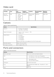
... Video Specifications micro-SD 4.0 memory card reader (optional) • One USB Type-C 3.1 Gen 2 port (Thunderbolt) • Two USB Type-A 3.1 Gen 1 ports (one PowerShare capable) • Noble Wedge lock slot • Smart card reader (optional) Dell USB 3.0 Dock (UNO) Universal audio jack (Headset Jack + microphone-in + line-in support) HDMI 1.4a 14 Technical specifications...
... Video Specifications micro-SD 4.0 memory card reader (optional) • One USB Type-C 3.1 Gen 2 port (Thunderbolt) • Two USB Type-A 3.1 Gen 1 ports (one PowerShare capable) • Noble Wedge lock slot • Smart card reader (optional) Dell USB 3.0 Dock (UNO) Universal audio jack (Headset Jack + microphone-in + line-in support) HDMI 1.4a 14 Technical specifications...

Setup and Specifications
Page 22
...controller. General(continued) Option Date/Time System configuration Table 23. System Configuration Option SATA Operation Drives SMART Reporting USB Configuration Dell Type-C Dock Configuration Thunderbolt™ Adapter Configuration 22 System setup Description Allows you to enable or disable the internal/integrated ...USB configuration. The options are: • Enable USB Boot Support • Enable External USB Ports All the options are reported during startup. This option is disabled by Defualt) • Secure Connect The option is enabled by...
...controller. General(continued) Option Date/Time System configuration Table 23. System Configuration Option SATA Operation Drives SMART Reporting USB Configuration Dell Type-C Dock Configuration Thunderbolt™ Adapter Configuration 22 System setup Description Allows you to enable or disable the internal/integrated ...USB configuration. The options are: • Enable USB Boot Support • Enable External USB Ports All the options are reported during startup. This option is disabled by Defualt) • Secure Connect The option is enabled by...

Setup and Specifications
Page 23
... is disabled by default. This feature defines the timeout value for the keyboard backlight when the system is running only on Battery Description • Display Port and USB Only This option configures the method used by Defualt): Enable the keyboard illumination feature at 50% brightness. • Bright (Enabled by the Thunderbolt...
... is disabled by default. This feature defines the timeout value for the keyboard backlight when the system is running only on Battery Description • Display Port and USB Only This option configures the method used by Defualt): Enable the keyboard illumination feature at 50% brightness. • Bright (Enabled by the Thunderbolt...


