
Owner's Manual
Page 3
... Drive...11 Installing The Hard Drive...12 Removing The Display Bezel...12 Installing the Display Bezel...13 Removing The Camera...13 Installing The Camera...13 Removing The Display Panel...13 Installing The Display Panel...14 Removing The Keyboard...15 Installing The Keyboard...16 Removing The Palmrest...16 Installing The Palmrest...17 Removing The Wireless Local Area Network (WLAN...
... Drive...11 Installing The Hard Drive...12 Removing The Display Bezel...12 Installing the Display Bezel...13 Removing The Camera...13 Installing The Camera...13 Removing The Display Panel...13 Installing The Display Panel...14 Removing The Keyboard...15 Installing The Keyboard...16 Removing The Palmrest...16 Installing The Palmrest...17 Removing The Wireless Local Area Network (WLAN...
Owner's Manual
Page 14
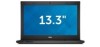
Remove the display panel from the display panel. 7. Connect the low-voltage differential signalling (LVDS) cable to secure the connection. 2. Peel off the adhesive tape that ... panel and attach the adhesive tape to the display panel. 3. Replace the adhesive tape that secures the low-voltage differential signalling (LVDS) connection to the keyboard. 5. Disconnect the LVDS cable from the computer. Align the display panel in its original position on the display assembly. 14 Installing The Display Panel 1. 4. Rotate...
Remove the display panel from the display panel. 7. Connect the low-voltage differential signalling (LVDS) cable to secure the connection. 2. Peel off the adhesive tape that ... panel and attach the adhesive tape to the display panel. 3. Replace the adhesive tape that secures the low-voltage differential signalling (LVDS) connection to the keyboard. 5. Disconnect the LVDS cable from the computer. Align the display panel in its original position on the display assembly. 14 Installing The Display Panel 1. 4. Rotate...
Owner's Manual
Page 15
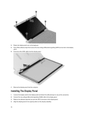
... a flat-head screwdriver to remove the keyboard retainers that secure the keyboard to the display assembly. 6. Lift the keyboard up and away from the system board. 6. Removing The Keyboard 1. Flip the keyboard over and lay it from the computer. 15 Lift the clip to release the keyboard cable and disconnect it on the palmrest. 5. 5. Tighten the screws to...
... a flat-head screwdriver to remove the keyboard retainers that secure the keyboard to the display assembly. 6. Lift the keyboard up and away from the system board. 6. Removing The Keyboard 1. Flip the keyboard over and lay it from the computer. 15 Lift the clip to release the keyboard cable and disconnect it on the palmrest. 5. 5. Tighten the screws to...

Owner's Manual
Page 16
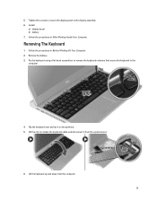
Insert the keyboard in the computer. 4. Removing The Palmrest 1. Remove the screws from the bottom of the computer, that secures the palmrest. 4. Press down until the keyboard clicks into place in its compartment. 3. Install the battery. 5. Follow the procedures in Before Working On Your Computer. 2. Follow the procedures in After Working Inside Your Computer. Remove the screws on the palmrest. 16 Connect the keyboard cable to the system board. 2. Remove: a) battery b) base cover c) keyboard d) hard drive 3. Installing The Keyboard 1.
Insert the keyboard in the computer. 4. Removing The Palmrest 1. Remove the screws from the bottom of the computer, that secures the palmrest. 4. Press down until the keyboard clicks into place in its compartment. 3. Install the battery. 5. Follow the procedures in Before Working On Your Computer. 2. Follow the procedures in After Working Inside Your Computer. Remove the screws on the palmrest. 16 Connect the keyboard cable to the system board. 2. Remove: a) battery b) base cover c) keyboard d) hard drive 3. Installing The Keyboard 1.
Owner's Manual
Page 17
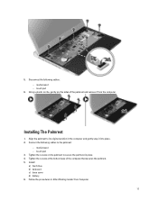
... After Working Insider Your Computer. 17 touch pad 3. 5. Using a plastic scribe, gently pry the sides of the computer that secures the palmrest. 5. Install: a) hard drive b) keyboard c) base cover d) battery 6. media board - touch pad 6. Tighten the screws at the bottom base of the palmrest and...
... After Working Insider Your Computer. 17 touch pad 3. 5. Using a plastic scribe, gently pry the sides of the computer that secures the palmrest. 5. Install: a) hard drive b) keyboard c) base cover d) battery 6. media board - touch pad 6. Tighten the screws at the bottom base of the palmrest and...

Owner's Manual
Page 18
... Before Working on Your Computer. 2. Follow the procedures in Before Working on Your Computer. 2. Follow the procedures in After Working Inside Your Computer. Remove: a) battery b) base cover c) hard drive d) keyboard e) palmrest 3. Remove the screws from the WLAN card. 4. Removing The Wireless Local Area Network (WLAN) Card 1. Installing The Wireless Local Area Network (WLAN) Card...
... Before Working on Your Computer. 2. Follow the procedures in Before Working on Your Computer. 2. Follow the procedures in After Working Inside Your Computer. Remove: a) battery b) base cover c) hard drive d) keyboard e) palmrest 3. Remove the screws from the WLAN card. 4. Removing The Wireless Local Area Network (WLAN) Card 1. Installing The Wireless Local Area Network (WLAN) Card...
Owner's Manual
Page 21
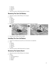
...coin-cell battery. 4. Follow the procedures in Before Working on Your Computer. 2. Remove: a) battery b) secure digital (SD) card c) base cover d) keyboard e) memory 21 Remove the coin-cell connector from the computer. Insert the coin-cell battery and connect...compartment. 2. Install: a) palmrest b) hard drive c) keyboard d) base cover e) battery 3. Installing The Coin-Cell Battery 1. Follow the procedures in After Working Inside Your Computer. Removing The System Board 1. Remove: a) battery b) base cover c) keyboard d) hard drive e) palmrest 3. Follow the procedures ...
...coin-cell battery. 4. Follow the procedures in Before Working on Your Computer. 2. Remove: a) battery b) secure digital (SD) card c) base cover d) keyboard e) memory 21 Remove the coin-cell connector from the computer. Insert the coin-cell battery and connect...compartment. 2. Install: a) palmrest b) hard drive c) keyboard d) base cover e) battery 3. Installing The Coin-Cell Battery 1. Follow the procedures in After Working Inside Your Computer. Removing The System Board 1. Remove: a) battery b) base cover c) keyboard d) hard drive e) palmrest 3. Follow the procedures ...
Owner's Manual
Page 22
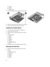
... system board from the system board. 4. Insert the system board into its slot. 3. Removing The Heat Sink 1. Follow the procedures in After Working Inside Your Computer. Follow the procedures in Before Working on Your Computer. 2. f) hard drive g) palmrest h) coin-... the power connector cable from the chassis. Connect the power connector cable to the system board. 2. Install: a) display assembly b) coin-cell c) palmrest d) memory e) hard drive f) keyboard g) base cover h) secure digital (SD) Card i) battery 5. Remove: a) battery b) secure digital (SD) card c) base cover...
... system board from the system board. 4. Insert the system board into its slot. 3. Removing The Heat Sink 1. Follow the procedures in After Working Inside Your Computer. Follow the procedures in Before Working on Your Computer. 2. f) hard drive g) palmrest h) coin-... the power connector cable from the chassis. Connect the power connector cable to the system board. 2. Install: a) display assembly b) coin-cell c) palmrest d) memory e) hard drive f) keyboard g) base cover h) secure digital (SD) Card i) battery 5. Remove: a) battery b) secure digital (SD) card c) base cover...
Owner's Manual
Page 23
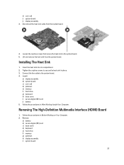
... Before Working on Your Computer. 2. Installing The Heat Sink 1. Install: a) display assembly b) system board c) coin-cell d) palmrest e) memory f) hard drive g) keyboard h) base cover i) secure digital (SD) card j) battery 5. Remove: a) battery b) secure digital (SD) card c) base cover d) keyboard e) hard drive f) memory g) palmrest h) display assembly i) system board 23 Insert the heat sink into its compartment...
... Before Working on Your Computer. 2. Installing The Heat Sink 1. Install: a) display assembly b) system board c) coin-cell d) palmrest e) memory f) hard drive g) keyboard h) base cover i) secure digital (SD) card j) battery 5. Remove: a) battery b) secure digital (SD) card c) base cover d) keyboard e) hard drive f) memory g) palmrest h) display assembly i) system board 23 Insert the heat sink into its compartment...
Owner's Manual
Page 24
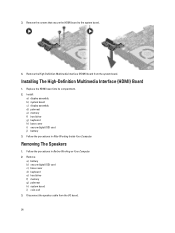
... Speakers 1. Install: a) display assembly b) system board c) display assembly d) palmrest e) memory f) hard drive g) keyboard h) base cover i) secure digital (SD) card j) battery 3. Remove: a) battery b) secure digital (SD) card c) base cover d) keyboard e) hard drive f) memory g) palmrest h) system board i) coin-cell 3. Remove the screws that secure the HDMI board to the system board. 4. 3. Installing The High-Definition Multimedia...
... Speakers 1. Install: a) display assembly b) system board c) display assembly d) palmrest e) memory f) hard drive g) keyboard h) base cover i) secure digital (SD) card j) battery 3. Remove: a) battery b) secure digital (SD) card c) base cover d) keyboard e) hard drive f) memory g) palmrest h) system board i) coin-cell 3. Remove the screws that secure the HDMI board to the system board. 4. 3. Installing The High-Definition Multimedia...
Owner's Manual
Page 25
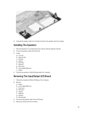
... compartments and route the cable through the channels. 2. Connect the speaker cable to the I /O) Board 1. Remove: a) battery b) secure digital (SD) card c) base cover d) hard drive e) memory f) keyboard g) palmrest h) system board 3. Place the speakers in its holder and remove the speakers from the chassis. 25 Follow the procedures in After Working Inside Your Computer...
... compartments and route the cable through the channels. 2. Connect the speaker cable to the I /O) Board 1. Remove: a) battery b) secure digital (SD) card c) base cover d) hard drive e) memory f) keyboard g) palmrest h) system board 3. Place the speakers in its holder and remove the speakers from the chassis. 25 Follow the procedures in After Working Inside Your Computer...
Owner's Manual
Page 26
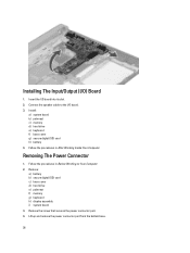
.... Connect the speaker cable to the I /O board into its slot. 2. Remove the screw that secures the power connector port. 4. Insert the I /O board. 3. Remove: a) battery b) secure digital (SD) card c) base cover d) hard drive e) palmrest f) memory g) keyboard h) display assembly i) system board 3. Lift up and remove the power connector port from the bottom base. 26 Installing The...
.... Connect the speaker cable to the I /O board into its slot. 2. Remove the screw that secures the power connector port. 4. Insert the I /O board. 3. Remove: a) battery b) secure digital (SD) card c) base cover d) hard drive e) palmrest f) memory g) keyboard h) display assembly i) system board 3. Lift up and remove the power connector port from the bottom base. 26 Installing The...
Statement of Volatility
Page 1
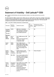
... removed from the component. System Two Volatile memory in OFF Yes Memory - The Dell Latitude™ 3330 contains both modules will be populated. List of Non-Volatile Components on board diags), PXE diags. April 2013 EEPROM assembly Stores panel manufacturing information, display configuration data. Statement of embedded No NA d Flash in Flash memory for keyboard...
... removed from the component. System Two Volatile memory in OFF Yes Memory - The Dell Latitude™ 3330 contains both modules will be populated. List of Non-Volatile Components on board diags), PXE diags. April 2013 EEPROM assembly Stores panel manufacturing information, display configuration data. Statement of embedded No NA d Flash in Flash memory for keyboard...


