
User Guide
Page 3
... PowerConnect 3424 21 PowerConnect 3424P 21 PowerConnect 3448 22 PowerConnect 3448P 22 Stacking Overview 22 Understanding the Stack Topology 23 Stacking Failover Topology 23 Stacking Members and Unit ID 23 Removing and Replacing Stacking Members 24 Exchanging Stacking Members 25 Switching from the Stack Master to the Backup Stack Master. . . . . . 27 Features Overview 28 Power over Ethernet...
... PowerConnect 3424 21 PowerConnect 3424P 21 PowerConnect 3448 22 PowerConnect 3448P 22 Stacking Overview 22 Understanding the Stack Topology 23 Stacking Failover Topology 23 Stacking Members and Unit ID 23 Removing and Replacing Stacking Members 24 Exchanging Stacking Members 25 Switching from the Stack Master to the Backup Stack Master. . . . . . 27 Features Overview 28 Power over Ethernet...

User Guide
Page 4
2 Hardware Description Port Description 37 PowerConnect 3424 Port Description 37 PowerConnect 3448 Port Description 38 SFP Ports 39 RS-232 Console Port 39 Physical Dimensions 40 LED Definitions 40 Gigabit Port LEDs 43 System LEDs 44 Power Supplies 45 Stack ID Button 47 Reset Button 47 Ventilation System 47 3 Installing the PowerConnect 3424/P and PowerConnect 3448/P Site Preparation 49 Unpacking 49 Package Contents 49...
2 Hardware Description Port Description 37 PowerConnect 3424 Port Description 37 PowerConnect 3448 Port Description 38 SFP Ports 39 RS-232 Console Port 39 Physical Dimensions 40 LED Definitions 40 Gigabit Port LEDs 43 System LEDs 44 Power Supplies 45 Stack ID Button 47 Reset Button 47 Ventilation System 47 3 Installing the PowerConnect 3424/P and PowerConnect 3448/P Site Preparation 49 Unpacking 49 Package Contents 49...

User Guide
Page 10
... 2-7. Figure 2-10. Figure 3-1. Figure 3-4. Figure 3-6. Figure 3-2. Figure 3-7. PowerConnect 3424 and PowerConnect 3424P . . . 21 PowerConnect 3448 and PowerConnect 3448P . . . 22 Stacking Ring Topology 23 PowerConnect 3448/P replaces PowerConnect 3448/P 26 PowerConect 3424/P port replaces PowerConnect 3448/P port 26 PowerConnect 3448/P port replaces PowerConect 3424/P Port 27 PowerConnect 3424 Front Panel 37 PowerConnect 3424 Back Panel 38 PowerConnect 3448 Front Panel 38 PowerConnect 3448 Back Panel 39 Console Port 39 RJ-45 Copper Based 10/100...
... 2-7. Figure 2-10. Figure 3-1. Figure 3-4. Figure 3-6. Figure 3-2. Figure 3-7. PowerConnect 3424 and PowerConnect 3424P . . . 21 PowerConnect 3448 and PowerConnect 3448P . . . 22 Stacking Ring Topology 23 PowerConnect 3448/P replaces PowerConnect 3448/P 26 PowerConect 3424/P port replaces PowerConnect 3448/P port 26 PowerConnect 3448/P port replaces PowerConect 3424/P Port 27 PowerConnect 3424 Front Panel 37 PowerConnect 3424 Back Panel 38 PowerConnect 3448 Front Panel 38 PowerConnect 3448 Back Panel 39 Console Port 39 RJ-45 Copper Based 10/100...

User Guide
Page 16
... Settings 377 CoS to Queue 379 DSCP to Queue 380 PowerConnect 3424 and PowerConnect 3448 RJ-45 100BaseT LED Indications 41 PowerConnect 3424P and PowerConnect 3448P RJ-45 Copper based 100BaseT LED Indications 42 PowerConnect 3424 and PowerConnect 3448 RJ-45 Copper based 100BaseT LED Indications 43 SFP Port LED Indications 43 System LED Indicators 44 Stacking LED Indications...
... Settings 377 CoS to Queue 379 DSCP to Queue 380 PowerConnect 3424 and PowerConnect 3448 RJ-45 100BaseT LED Indications 41 PowerConnect 3424P and PowerConnect 3448P RJ-45 Copper based 100BaseT LED Indications 42 PowerConnect 3424 and PowerConnect 3448 RJ-45 Copper based 100BaseT LED Indications 43 SFP Port LED Indications 43 System LED Indicators 44 Stacking LED Indications...

User Guide
Page 21
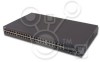
... as stand-alone, multi-layer, switching devices or stackable devices with minimal management. The PowerConnect 3424P is stacked. The PowerConnect 3424 and 3448 series include the following device types: • PowerConnect 3424 • PowerConnect 3424P • PowerConnect 3448 • PowerConnect 3448P PowerConnect 3424 The PowerConnect 3424 provides 24 10/100Mbps ports plus two SFP ports, and two Copper ports which can be used to...
... as stand-alone, multi-layer, switching devices or stackable devices with minimal management. The PowerConnect 3424P is stacked. The PowerConnect 3424 and 3448 series include the following device types: • PowerConnect 3424 • PowerConnect 3424P • PowerConnect 3448 • PowerConnect 3448P PowerConnect 3424 The PowerConnect 3424 provides 24 10/100Mbps ports plus two SFP ports, and two Copper ports which can be used to...

User Guide
Page 22
... of a stack. PowerConnect 3448 and PowerConnect 3448P Stacking Overview PowerConnect 3424/P and PowerConnect 3448/P stacking provides multiple switch management through which can be running the same software version. The device also provides one RS-232 console port. Figure 1-2. Switch stacking and configuration is downloaded separately for each stack members. www.dell.com | support.dell.com PowerConnect 3448 The PowerConnect 3448 provides 48 10/100Mbps ports plus two...
... of a stack. PowerConnect 3448 and PowerConnect 3448P Stacking Overview PowerConnect 3424/P and PowerConnect 3448/P stacking provides multiple switch management through which can be running the same software version. The device also provides one RS-232 console port. Figure 1-2. Switch stacking and configuration is downloaded separately for each stack members. www.dell.com | support.dell.com PowerConnect 3448 The PowerConnect 3448 provides 48 10/100Mbps ports plus two...

User Guide
Page 23
...the stack are resolved, the device can be repaired to the stack without any system downtime. With the PowerConnect 3424/P and PowerConnect 3448/P stack, the system automatically switches to send traffic. The system discovers the optimal path on which it reaches its destination. An SNMP message... default Unit ID of the stand-alone unit. If the device is connected to Stacking Failover Topology. Understanding the Stack Topology The PowerConnect 3400 series operates in a chain formation. Stacking Failover Topology If a failure occurs in the ring becomes nonfunctional, or a link...
...the stack are resolved, the device can be repaired to the stack without any system downtime. With the PowerConnect 3424/P and PowerConnect 3448/P stack, the system automatically switches to send traffic. The system discovers the optimal path on which it reaches its destination. An SNMP message... default Unit ID of the stand-alone unit. If the device is connected to Stacking Failover Topology. Understanding the Stack Topology The PowerConnect 3400 series operates in a chain formation. Stacking Failover Topology If a failure occurs in the ring becomes nonfunctional, or a link...

User Guide
Page 25
...Introduction 25 Unit IDs are saved in the unit and are changed only through explicit user configuration. Non-present ports are reassigned Unit IDs • Units toggle between Stacking Mode and Stand-alone Mode Each time the system reboots... through the CLI or SNMP interfaces. For example, • If a PowerConnect 3424/P replaces PowerConnect 3424/P, all port configurations remain the same. • If a PowerConnect 3448/P replaces the PowerConnect 3448/P, all units in the PowerConnect OpenManage Switch Administrator home page, and can be configured through the web management system....
...Introduction 25 Unit IDs are saved in the unit and are changed only through explicit user configuration. Non-present ports are reassigned Unit IDs • Units toggle between Stacking Mode and Stand-alone Mode Each time the system reboots... through the CLI or SNMP interfaces. For example, • If a PowerConnect 3424/P replaces PowerConnect 3424/P, all port configurations remain the same. • If a PowerConnect 3448/P replaces the PowerConnect 3448/P, all units in the PowerConnect OpenManage Switch Administrator home page, and can be configured through the web management system....

User Guide
Page 27
The running configuration file is performed with either via web interface or the CLI. Switching between Stack Master and the Backup Master, and continues running on the Backup Master. PowerConnect 3448/P port replaces PowerConect 3424/P Port Same Configuration Same Configuration Switching from the Stack Master to the Backup Stack Master The Backup Master replaces the Stack Master...
The running configuration file is performed with either via web interface or the CLI. Switching between Stack Master and the Backup Master, and continues running on the Backup Master. PowerConnect 3448/P port replaces PowerConect 3424/P Port Same Configuration Same Configuration Switching from the Stack Master to the Backup Stack Master The Backup Master replaces the Stack Master...

User Guide
Page 38
.../100 Base-T Ports 2, 4, 6, 8, ...48 G1 G2 1000Base-X SFP Ports G3 G4 Stacking Ports The front panel contains 48 RJ-45 ports number 1-48. www.dell.com | support.dell.com There are all the device LEDs. Console Port RPS Connector Power Connector PowerConnect 3448 Port Description The PowerConnect 3448 device is used as 1000Base-X SFP ports • 2 Gigabit ports - Ports G3- RJ-45 ports designated as 1000Base-T ports • Console port - RS-232...
.../100 Base-T Ports 2, 4, 6, 8, ...48 G1 G2 1000Base-X SFP Ports G3 G4 Stacking Ports The front panel contains 48 RJ-45 ports number 1-48. www.dell.com | support.dell.com There are all the device LEDs. Console Port RPS Connector Power Connector PowerConnect 3448 Port Description The PowerConnect 3448 device is used as 1000Base-X SFP ports • 2 Gigabit ports - Ports G3- RJ-45 ports designated as 1000Base-T ports • Console port - RS-232...

User Guide
Page 39
...) which is used to 115,200 bps. Console Port Hardware Description 39 PowerConnect 3448 Back Panel Console Port RPS Connector Power Connector The back panel contains an RPS connector, console port and power connector. The default baud rate is prevented. Figure 2-5. SFP Ports The Small Form Factor Plugable (SFP) ports are a Two-Wire Serial Interface (TWSI) for... to manually reset the device. The baud rate can be configured from 2400 bps up to select the unit number. The following figure illustrates the PowerConnect 3448 back panel: Figure 2-4.
...) which is used to 115,200 bps. Console Port Hardware Description 39 PowerConnect 3448 Back Panel Console Port RPS Connector Power Connector The back panel contains an RPS connector, console port and power connector. The default baud rate is prevented. Figure 2-5. SFP Ports The Small Form Factor Plugable (SFP) ports are a Two-Wire Serial Interface (TWSI) for... to manually reset the device. The baud rate can be configured from 2400 bps up to select the unit number. The following figure illustrates the PowerConnect 3448 back panel: Figure 2-4.

User Guide
Page 40
...dell.com | support.dell.com Physical Dimensions The PowerConnect 3424/P and PowerConnect 3448/P devices have the following figure illustrates the 10/100 Base-T port LEDs on The PowerConnect 3424 /P and PowerConnect 3448/P switches: Figure 2-6. RJ-45 Copper Based 10/100 BaseT LEDs Speed/LNK/ACT FDX Speed/LNK/ACT FDX The RJ-45 100 Base-T port...the status of the port, while the link/duplex/activity LED is located on the left side of links, power supplies, fans, and system diagnostics. The speed LED is located on the PowerConnect 3424 /P and PowerConnect 3448/P has two LEDs ...
...dell.com | support.dell.com Physical Dimensions The PowerConnect 3424/P and PowerConnect 3448/P devices have the following figure illustrates the 10/100 Base-T port LEDs on The PowerConnect 3424 /P and PowerConnect 3448/P switches: Figure 2-6. RJ-45 Copper Based 10/100 BaseT LEDs Speed/LNK/ACT FDX Speed/LNK/ACT FDX The RJ-45 100 Base-T port...the status of the port, while the link/duplex/activity LED is located on the left side of links, power supplies, fans, and system diagnostics. The speed LED is located on the PowerConnect 3424 /P and PowerConnect 3448/P has two LEDs ...

User Guide
Page 41
...: Table 2-1. RJ-45 1000 BaseT LED The RJ-45 LED indications for PowerConnect 3424 and PowerConnect 3448 are described in the following figure illustrates the 100 Base-T LEDs. The port is either transmitting or receiving data at 100 Mbps. PowerConnect 3424 and PowerConnect 3448 RJ-45 100BaseT LED Indications LED Link/Activity/Speed FDX Color Green Static...
...: Table 2-1. RJ-45 1000 BaseT LED The RJ-45 LED indications for PowerConnect 3424 and PowerConnect 3448 are described in the following figure illustrates the 100 Base-T LEDs. The port is either transmitting or receiving data at 100 Mbps. PowerConnect 3424 and PowerConnect 3448 RJ-45 100BaseT LED Indications LED Link/Activity/Speed FDX Color Green Static...

User Guide
Page 43
... running at 1000 Mbps. The following table describes the Gigabit (stacking port) LEDs: Table 2-3. SFP Port LEDs The SFP port LED indications are round in Half Duplex mode. Hardware Description 43 OFF The port is currently not operating. The port is currently not linked. PowerConnect 3424 and PowerConnect 3448 RJ-45 Copper based 100BaseT LED Indications LED Link/Activity...
... running at 1000 Mbps. The following table describes the Gigabit (stacking port) LEDs: Table 2-3. SFP Port LEDs The SFP port LED indications are round in Half Duplex mode. Hardware Description 43 OFF The port is currently not operating. The port is currently not linked. PowerConnect 3424 and PowerConnect 3448 RJ-45 Copper based 100BaseT LED Indications LED Link/Activity...

User Guide
Page 44
...3424 and 3448 ) Redundant Power Supply (RPS) (models: 3424P and 3448P ) Diagnostics (DIAG) Temperature (TEMP) Fan (FAN) Color Green Static OFF Green Static Description The switch is turned off. Green Static The system diagnostic test passed successfully. www.dell.com | support.dell.com System ...temperature range. Green Flashing The system diagnostic test is not plugged in. Red Static One or more of The PowerConnect 3424 /P and PowerConnect 3448/P devices provide information about the power supplies, fans, thermal conditions, and diagnostics. The redundant power supply is ...
...3424 and 3448 ) Redundant Power Supply (RPS) (models: 3424P and 3448P ) Diagnostics (DIAG) Temperature (TEMP) Fan (FAN) Color Green Static OFF Green Static Description The switch is turned off. Green Static The system diagnostic test passed successfully. www.dell.com | support.dell.com System ...temperature range. Green Flashing The system diagnostic test is not plugged in. Red Static One or more of The PowerConnect 3424 /P and PowerConnect 3448/P devices provide information about the power supplies, fans, thermal conditions, and diagnostics. The redundant power supply is ...

User Guide
Page 45
...device has an internal power supply unit (AC unit) and a connector to connect PowerConnect 3424/P and PowerConnect 3448/P devices to a PowerConnect EPS-470 unit, or to connect PowerConnect 3424 and PowerConnect 3448 devices to 63 Hz. Hardware Description 45 The device is the Stack Master The ...Green Static OFF Description The switch is not designated as Stacking Unit N. Power supply LEDs indicate the status of 370W for 24 ports PoE device. The Stacking LEDs indicate the unit position in the stack. The PowerConnect 3424/P and PowerConnect 3448/P devices have an internal ...
...device has an internal power supply unit (AC unit) and a connector to connect PowerConnect 3424/P and PowerConnect 3448/P devices to a PowerConnect EPS-470 unit, or to connect PowerConnect 3424 and PowerConnect 3448 devices to 63 Hz. Hardware Description 45 The device is the Stack Master The ...Green Static OFF Description The switch is not designated as Stacking Unit N. Power supply LEDs indicate the status of 370W for 24 ports PoE device. The Stacking LEDs indicate the unit position in the stack. The PowerConnect 3424/P and PowerConnect 3448/P devices have an internal ...
User Guide
Page 46
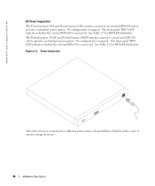
...front panel "RPS" LED indicates whether the external RPS-600 is required. See Table 2-5 for RPS LED definition. The PowerConnect 3424/P and PowerConnect 3448/P switches connect to an external EPS-470 unit to provide a redundant power option. Figure 2-11. See Table 2-5 for RPS...event of a power outage decreases. 46 Hardware Description Power Connection When the device is required. www.dell.com | support.dell.com DC Power Supply Unit The PowerConnect 3424 and PowerConnect 3448 switches connect to an external RPS-600 unit to provide a redundant power option. The front panel "RPS...
...front panel "RPS" LED indicates whether the external RPS-600 is required. See Table 2-5 for RPS LED definition. The PowerConnect 3424/P and PowerConnect 3448/P switches connect to an external EPS-470 unit to provide a redundant power option. Figure 2-11. See Table 2-5 for RPS...event of a power outage decreases. 46 Hardware Description Power Connection When the device is required. www.dell.com | support.dell.com DC Power Supply Unit The PowerConnect 3424 and PowerConnect 3448 switches connect to an external RPS-600 unit to provide a redundant power option. The front panel "RPS...

User Guide
Page 47
Hardware Description 47 To select a Unit ID for the Stack Master and members. Reset Button The PowerConnect 3424/P and PowerConnect 3448/P switches have a reset button, located on the Unit ID of the switch is activated by observing the LED that is either 1 or 2 depending on the front panel, for ...manual reset of 1 or 2. Ventilation System The PowerConnect 3424/P and PowerConnect 3448/P switches with the PoE feature have two built-in fans. If a Unit ID has already been selected, press the Stack ID button...
Hardware Description 47 To select a Unit ID for the Stack Master and members. Reset Button The PowerConnect 3424/P and PowerConnect 3448/P switches have a reset button, located on the Unit ID of the switch is activated by observing the LED that is either 1 or 2 depending on the front panel, for ...manual reset of 1 or 2. Ventilation System The PowerConnect 3424/P and PowerConnect 3448/P switches with the PoE feature have two built-in fans. If a Unit ID has already been selected, press the Stack ID button...

User Guide
Page 49
...Supply (RPS) is currently installed by checking that the PoE LEDs on the front panel are included: • Device/Switch • AC power cable • RS-232 crossover cable • Self-adhesive rubber pads • Rack-mount kit... mounting kit • Documentation CD • Product Information Guide Installing the PowerConnect 3424/P and PowerConnect 3448/P 49 Installing the PowerConnect 3424/P and PowerConnect 3448/P Site Preparation The PowerConnect 3424 /P and PowerConnect 3448/P devices can be mounted in a standard 48.26-am (19-inch) equipment rack, placed on a tabletop or mounted...
...Supply (RPS) is currently installed by checking that the PoE LEDs on the front panel are included: • Device/Switch • AC power cable • RS-232 crossover cable • Self-adhesive rubber pads • Rack-mount kit... mounting kit • Documentation CD • Product Information Guide Installing the PowerConnect 3424/P and PowerConnect 3448/P 49 Installing the PowerConnect 3424/P and PowerConnect 3448/P Site Preparation The PowerConnect 3424 /P and PowerConnect 3448/P devices can be mounted in a standard 48.26-am (19-inch) equipment rack, placed on a tabletop or mounted...

User Guide
Page 50
The Console port is on the back panel of damage. 1 Place the box on a clean flat surface. 2 Open the box or remove the box top. 3 Carefully remove the ... PowerConnect 3424/P and PowerConnect 3448/P devices. Installing in a Rack CAUTION: Read the Safety Information included in a rack or cabinet. CAUTION: Disconnect all packing material. 5 Inspect the device and accessories for safety information on the back panel. Mounting the Device The following mounting instructions apply to or that support the SWI. www.dell.com | support.dell...
The Console port is on the back panel of damage. 1 Place the box on a clean flat surface. 2 Open the box or remove the box top. 3 Carefully remove the ... PowerConnect 3424/P and PowerConnect 3448/P devices. Installing in a Rack CAUTION: Read the Safety Information included in a rack or cabinet. CAUTION: Disconnect all packing material. 5 Inspect the device and accessories for safety information on the back panel. Mounting the Device The following mounting instructions apply to or that support the SWI. www.dell.com | support.dell...


