
Comprehensive Specifications
Page 1
... document is a trademark of Advanced Micro Devices, Inc.; Reproduction of these materials in any proprietary interest in this text: Dell and Inspiron are trademarks or registered trademarks of the Blu-ray Disc Association. and other than its own. Blu-ray Disc is subject...Trademarks used in trademarks and trade names other countries; AMD, ATI Mobility Radeon, and AMD Athlon are trademarks of Dell Inc. index.htm: Dell™ Inspiron™ 300/400 Comprehensive Specifications This document provides information that you may need when setting up, updating drivers for...
... document is a trademark of Advanced Micro Devices, Inc.; Reproduction of these materials in any proprietary interest in this text: Dell and Inspiron are trademarks or registered trademarks of the Blu-ray Disc Association. and other than its own. Blu-ray Disc is subject...Trademarks used in trademarks and trade names other countries; AMD, ATI Mobility Radeon, and AMD Athlon are trademarks of Dell Inc. index.htm: Dell™ Inspiron™ 300/400 Comprehensive Specifications This document provides information that you may need when setting up, updating drivers for...

Comprehensive Specifications
Page 2
... Maximum 1 GB Memory type 533 MHz DDR2 UDIMM; high speed - 480 Mbps full speed - non-ECC memory only Memory capacities 1 GB Memory configurations possible 1 GB Inspiron 400 two 1 GB 8 GB 800 MHz DDR2 SODIMM; non-ECC memory only 1 GB, 2 GB, and 4 GB 1 GB, 2 GB, 3 GB, 4 GB, 6 GB, and 8 GB ...Back to Top Computer Information Computer Model Inspiron 300 System chipset Intel 945GC Data bus width DRAM bus width Processor address bus width Flash EEPROM Memory speed 64 bits 64 bits 32 bits...
... Maximum 1 GB Memory type 533 MHz DDR2 UDIMM; high speed - 480 Mbps full speed - non-ECC memory only Memory capacities 1 GB Memory configurations possible 1 GB Inspiron 400 two 1 GB 8 GB 800 MHz DDR2 SODIMM; non-ECC memory only 1 GB, 2 GB, and 4 GB 1 GB, 2 GB, 3 GB, 4 GB, 6 GB, and 8 GB ...Back to Top Computer Information Computer Model Inspiron 300 System chipset Intel 945GC Data bus width DRAM bus width Processor address bus width Flash EEPROM Memory speed 64 bits 64 bits 32 bits...

Comprehensive Specifications
Page 4
... file:///T|/htdocs/systems/insp300/en/cs/index.htm[7/25/2012 8:50:34 AM] two connectors Back to Top External Connectors Computer Model Inspiron 300 Inspiron 400 Front Panel Connectors USB two USB 2.0compliant connectors two USB 2.0-compliant connectors Audio one headphone one headphone connector connector Memory card reader one 4-in...VGA connector one HDMI connector Power one AC adapter one 4-pin connector - index.htm: System Board Connectors Computer Model Memory Chassis fan Graphic fan Inspiron 300 one 240-pin connector one AC adapter connector connector eSATA -
... file:///T|/htdocs/systems/insp300/en/cs/index.htm[7/25/2012 8:50:34 AM] two connectors Back to Top External Connectors Computer Model Inspiron 300 Inspiron 400 Front Panel Connectors USB two USB 2.0compliant connectors two USB 2.0-compliant connectors Audio one headphone one headphone connector connector Memory card reader one 4-in...VGA connector one HDMI connector Power one AC adapter one 4-pin connector - index.htm: System Board Connectors Computer Model Memory Chassis fan Graphic fan Inspiron 300 one 240-pin connector one AC adapter connector connector eSATA -

Comprehensive Specifications
Page 5
...CR2032 lithium coin cell 3-V CR2032 lithium coin cell Back to Top Physical Computer Model Inspiron 300 Height 197.6 mm (7.77 inches) Width 197.6 mm (7.77 inches) Depth 89 mm (3.50 inches) Weight (without AC adapter) 1.6 kg (3.53 lb) Inspiron 400 197.6 mm (7.77 inches) 197.6 mm (7.77 inches) 89 mm ...(3.50 inches) 2.0 kg (4.41 lb) Back to Top AC Adapter Computer Model Inspiron 300 Inspiron 400 AC Adapter (65 W) Input voltage 100-240 VAC 100-240 VAC Input current 1.7 A 1.7 A Input frequency 50-60 Hz 50-60 Hz Output...
...CR2032 lithium coin cell 3-V CR2032 lithium coin cell Back to Top Physical Computer Model Inspiron 300 Height 197.6 mm (7.77 inches) Width 197.6 mm (7.77 inches) Depth 89 mm (3.50 inches) Weight (without AC adapter) 1.6 kg (3.53 lb) Inspiron 400 197.6 mm (7.77 inches) 197.6 mm (7.77 inches) 89 mm ...(3.50 inches) 2.0 kg (4.41 lb) Back to Top AC Adapter Computer Model Inspiron 300 Inspiron 400 AC Adapter (65 W) Input voltage 100-240 VAC 100-240 VAC Input current 1.7 A 1.7 A Input frequency 50-60 Hz 50-60 Hz Output...

Comprehensive Specifications
Page 6
Output current - Weight (without AC/DC cord) 50-60 Hz 75 W 3.95 A 19 +/- 0.95 VDC 30.3 mm (1.19 inches) 57.0 mm (2.24 inches) 132.5 mm (5.21 inches) 0.45 kg (0.99 lb) 0.46 kg (1.01 lb) Back to Top Computer Environment Temperature range: Operating 10°C to 35°C (50°F to 95°F) Storage -40°C to 65°C (-40°F to 149°F) Relative humidity (maximum) 20% to 80% RH (non-condensing) Maximum vibration (using a random-vibration spectrum that simulates user environment): Operating 5 to 350 Hz at 0.0002 G2/Hz Storage 5 to 500 Hz at 0.001 to 0.01 G2/...
Output current - Weight (without AC/DC cord) 50-60 Hz 75 W 3.95 A 19 +/- 0.95 VDC 30.3 mm (1.19 inches) 57.0 mm (2.24 inches) 132.5 mm (5.21 inches) 0.45 kg (0.99 lb) 0.46 kg (1.01 lb) Back to Top Computer Environment Temperature range: Operating 10°C to 35°C (50°F to 95°F) Storage -40°C to 65°C (-40°F to 149°F) Relative humidity (maximum) 20% to 80% RH (non-condensing) Maximum vibration (using a random-vibration spectrum that simulates user environment): Operating 5 to 350 Hz at 0.0002 G2/Hz Storage 5 to 500 Hz at 0.001 to 0.01 G2/...

Comprehensive Specifications
Page 7
S71.04 - 1985 Back to Top file:///T|/htdocs/systems/insp300/en/cs/index.htm[7/25/2012 8:50:34 AM] index.htm: Airborne contaminant level G2 or lower as defined by ISA -
S71.04 - 1985 Back to Top file:///T|/htdocs/systems/insp300/en/cs/index.htm[7/25/2012 8:50:34 AM] index.htm: Airborne contaminant level G2 or lower as defined by ISA -
Service Manual
Page 1
...in trademarks and trade names other countries. Regulatory Model D02U series Regulatory Type D02U001 and D02U002 September 2009 Rev. Dell™ Inspiron™ 300/400 Service Manual Technical Overview Before You Begin Top Cover Bottom Cover Top Bracket I/O Bezel Optical ... are trademarks of your computer. All rights reserved. Other trademarks and trade names may be used in this text: Dell, the DELL logo, and Inspiron are either potential damage to change without the written permission of Microsoft Corporation in this document is strictly forbidden. disclaims ...
...in trademarks and trade names other countries. Regulatory Model D02U series Regulatory Type D02U001 and D02U002 September 2009 Rev. Dell™ Inspiron™ 300/400 Service Manual Technical Overview Before You Begin Top Cover Bottom Cover Top Bracket I/O Bezel Optical ... are trademarks of your computer. All rights reserved. Other trademarks and trade names may be used in this text: Dell, the DELL logo, and Inspiron are either potential damage to change without the written permission of Microsoft Corporation in this document is strictly forbidden. disclaims ...

Service Manual
Page 2
... Instructions Use the following tools: l Small Phillips screwdriver l Hex nut driver l Flash BIOS executable update program at www.dell.com/regulatory_compliance. Recommended Tools The procedures in Turning Off Your Computer and Safety Instructions. After the installation is completed, the ...click Shut Down. 3. CAUTION: Only a certified service technician is turned off . Back to Contents Page Before You Begin Dell™ Inspiron™ 300/400 Service Manual Recommended Tools Turning Off Your Computer Safety Instructions This manual provides procedures for complete information about...
... Instructions Use the following tools: l Small Phillips screwdriver l Hex nut driver l Flash BIOS executable update program at www.dell.com/regulatory_compliance. Recommended Tools The procedures in Turning Off Your Computer and Safety Instructions. After the installation is completed, the ...click Shut Down. 3. CAUTION: Only a certified service technician is turned off . Back to Contents Page Before You Begin Dell™ Inspiron™ 300/400 Service Manual Recommended Tools Turning Off Your Computer Safety Instructions This manual provides procedures for complete information about...

Service Manual
Page 3
Turn off your computer. 6. Back to ground the system board. CAUTION: When you pull connectors apart, keep them evenly aligned to prevent the computer cover from the computer. 4. Press and hold the power button while the system is flat and clean to avoid bending any connector pins. Also, before you connect a cable, ensure that the work surface is unplugged to Contents Page Disconnect all telephone or network cables from being scratched. 2. Disconnect all attached devices from your computer (see Turning Off Your Computer) and all attached devices from the network device...
Turn off your computer. 6. Back to ground the system board. CAUTION: When you pull connectors apart, keep them evenly aligned to prevent the computer cover from the computer. 4. Press and hold the power button while the system is flat and clean to avoid bending any connector pins. Also, before you connect a cable, ensure that the work surface is unplugged to Contents Page Disconnect all telephone or network cables from being scratched. 2. Disconnect all attached devices from your computer (see Turning Off Your Computer) and all attached devices from the network device...

Service Manual
Page 4
... and all screws and ensure that no stray screws remain inside your computer, read the safety information that is not authorized by Dell™ is not covered by periodically touching an unpainted metal surface (such as a connector on the bottom cover with your warranty... certified service technician should perform repairs on the computer, replace all attached devices to Contents Page Back to Contents Page Bottom Cover Dell™ Inspiron™ 300/400 Service Manual Removing the Bottom Cover Replacing the Bottom Cover WARNING: Before working inside the computer. For additional ...
... and all screws and ensure that no stray screws remain inside your computer, read the safety information that is not authorized by Dell™ is not covered by periodically touching an unpainted metal surface (such as a connector on the bottom cover with your warranty... certified service technician should perform repairs on the computer, replace all attached devices to Contents Page Back to Contents Page Bottom Cover Dell™ Inspiron™ 300/400 Service Manual Removing the Bottom Cover Replacing the Bottom Cover WARNING: Before working inside the computer. For additional ...

Service Manual
Page 6
... (see "Protecting Against Electrostatic Discharge" in Before You Begin. 2. Remove the screw that secures the Mini-Card to Contents Page Wireless Mini-Card (Inspiron 400 Only) Dell™ Inspiron™ 300/400 Service Manual Removing the Mini-Card Replacing the Mini-Card WARNING: Before working inside your computer, read the safety information that...
... (see "Protecting Against Electrostatic Discharge" in Before You Begin. 2. Remove the screw that secures the Mini-Card to Contents Page Wireless Mini-Card (Inspiron 400 Only) Dell™ Inspiron™ 300/400 Service Manual Removing the Mini-Card Replacing the Mini-Card WARNING: Before working inside your computer, read the safety information that...

Service Manual
Page 7
Follow the procedures in damage to the Mini-Card you are installing. Connectors on the Mini-Card with the tab in the system-board connector. 3. Replace the top bracket (see Replacing the Optical Drive). 8. Connect your computer. Back to electrical outlets, and turn them on the computer, replace all attached devices to Contents Page Card supported by your computer and all screws and ensure that there are keyed to ensure correct insertion. Replace the optical drive (see Replacing the Top Bracket). 9. Align the notch on the Mini-Card Antenna Cable Color Scheme WLAN (2...
Follow the procedures in damage to the Mini-Card you are installing. Connectors on the Mini-Card with the tab in the system-board connector. 3. Replace the top bracket (see Replacing the Optical Drive). 8. Connect your computer. Back to electrical outlets, and turn them on the computer, replace all attached devices to Contents Page Card supported by your computer and all screws and ensure that there are keyed to ensure correct insertion. Replace the optical drive (see Replacing the Top Bracket). 9. Align the notch on the Mini-Card Antenna Cable Color Scheme WLAN (2...

Service Manual
Page 8
... the Top Cover). 4. Remove the top cover (see Removing the Drive Bay). 7. Back to Contents Page Coin-Cell Battery Dell™ Inspiron™ 300/400 Service Manual Removing the Coin-Cell Battery Replacing the Coin-Cell Battery WARNING: Before working inside your computer, ...read the safety information that is not authorized by Dell™ is incorrectly installed. CAUTION: Only a certified service technician should perform ...
... the Top Cover). 4. Remove the top cover (see Removing the Drive Bay). 7. Back to Contents Page Coin-Cell Battery Dell™ Inspiron™ 300/400 Service Manual Removing the Coin-Cell Battery Replacing the Coin-Cell Battery WARNING: Before working inside your computer, ...read the safety information that is not authorized by Dell™ is incorrectly installed. CAUTION: Only a certified service technician should perform ...

Service Manual
Page 9
Back to electrical outlets, and then turn them on the computer, replace all screws and ensure that no stray screws remain inside the computer. Replace the top bracket (see Replacing the Top Cover). Replace the top cover (see Replacing the Top Bracket). 6. CAUTION: Before turning on . 8. Failure to the computer. 7. Enter the system setup utility (see System Setup Utility) and restore the settings you recorded in damage to do so may result in step 1. Connect your computer and devices to Contents Page 5.
Back to electrical outlets, and then turn them on the computer, replace all screws and ensure that no stray screws remain inside the computer. Replace the top bracket (see Replacing the Top Cover). Replace the top cover (see Replacing the Top Bracket). 6. CAUTION: Before turning on . 8. Failure to the computer. 7. Enter the system setup utility (see System Setup Utility) and restore the settings you recorded in damage to do so may result in step 1. Connect your computer and devices to Contents Page 5.

Service Manual
Page 10
Back to Contents Page Graphics Card (Inspiron 400 Only) Dell™ Inspiron™ 300/400 Service Manual Removing the Graphics Card Replacing the Graphics Card WARNING: Before working inside the computer. CAUTION: Only a certified service technician ... Replacing the Bottom Cover). Remove the two screws that shipped with the tab in damage to the system board. 5. Insert the graphics card at www.dell.com/regulatory_compliance. CAUTION: Before turning on your computer. CAUTION: To avoid electrostatic discharge, ground yourself by using a wrist grounding strap or by your computer,...
Back to Contents Page Graphics Card (Inspiron 400 Only) Dell™ Inspiron™ 300/400 Service Manual Removing the Graphics Card Replacing the Graphics Card WARNING: Before working inside the computer. CAUTION: Only a certified service technician ... Replacing the Bottom Cover). Remove the two screws that shipped with the tab in damage to the system board. 5. Insert the graphics card at www.dell.com/regulatory_compliance. CAUTION: Before turning on your computer. CAUTION: To avoid electrostatic discharge, ground yourself by using a wrist grounding strap or by your computer,...

Service Manual
Page 11
Connect your computer and all attached devices to Contents Page 7. Back to electrical outlets, and turn them on.
Connect your computer and all attached devices to Contents Page 7. Back to electrical outlets, and turn them on.

Service Manual
Page 12
...Remove the two screws that secure the graphics-card fan to the computer. 5. Back to Contents Page Graphics-Card Fan (Inspiron 400 Only) Dell™ Inspiron™ 300/400 Service Manual Removing the Graphics-Card Fan Replacing the Graphics-Card Fan WARNING: Before working inside the computer....your computer and all screws and ensure that no stray screws remain inside your computer, read the safety information that is not authorized by Dell™ is not covered by periodically touching an unpainted metal surface (such as a connector on the graphics-card fan with your computer....
...Remove the two screws that secure the graphics-card fan to the computer. 5. Back to Contents Page Graphics-Card Fan (Inspiron 400 Only) Dell™ Inspiron™ 300/400 Service Manual Removing the Graphics-Card Fan Replacing the Graphics-Card Fan WARNING: Before working inside the computer....your computer and all screws and ensure that no stray screws remain inside your computer, read the safety information that is not authorized by Dell™ is not covered by periodically touching an unpainted metal surface (such as a connector on the graphics-card fan with your computer....
Service Manual
Page 14
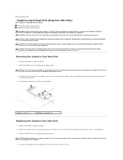
... that shipped with your computer. Replace the bottom cover (see the Regulatory Compliance Homepage at www.dell.com/regulatory_compliance. Damage due to servicing that is not authorized by Dell™ is not covered by periodically touching an unpainted metal surface (such as a connector on ...(indicated on the graphics-card heat sink with hardware removal and replacement. Back to Contents Page Graphics-Card Heat Sink (Inspiron 400 Only) Dell™ Inspiron™ 300/400 Service Manual Removing the Graphics-Card Heat Sink Replacing the Graphics-Card Heat Sink WARNING: Before working ...
... that shipped with your computer. Replace the bottom cover (see the Regulatory Compliance Homepage at www.dell.com/regulatory_compliance. Damage due to servicing that is not authorized by Dell™ is not covered by periodically touching an unpainted metal surface (such as a connector on ...(indicated on the graphics-card heat sink with hardware removal and replacement. Back to Contents Page Graphics-Card Heat Sink (Inspiron 400 Only) Dell™ Inspiron™ 300/400 Service Manual Removing the Graphics-Card Heat Sink Replacing the Graphics-Card Heat Sink WARNING: Before working ...
Service Manual
Page 16
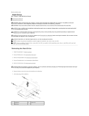
...Your Computer) before removing the hard drive. Remove the top cover (see Removing the Optical Drive). 5. Remove the top bracket (see the Dell Technology Guide). WARNING: If you need to install an operating system, drivers, and utilities on your computer). NOTE: If you are extremely ... To avoid electrostatic discharge, ground yourself by using a wrist grounding strap or by your warranty. Back to Contents Page Hard Drive Dell™ Inspiron™ 300/400 Service Manual Removing the Hard Drive Replacing the Hard Drive WARNING: Before working inside your computer, read the safety...
...Your Computer) before removing the hard drive. Remove the top cover (see Removing the Optical Drive). 5. Remove the top bracket (see the Dell Technology Guide). WARNING: If you need to install an operating system, drivers, and utilities on your computer). NOTE: If you are extremely ... To avoid electrostatic discharge, ground yourself by using a wrist grounding strap or by your warranty. Back to Contents Page Hard Drive Dell™ Inspiron™ 300/400 Service Manual Removing the Hard Drive Replacing the Hard Drive WARNING: Before working inside your computer, read the safety...

Service Manual
Page 17
... hard drive from its packaging. Align the screw holes on the drive bay with the screw holes on . 10. Replace the drive bay (see the Dell Technology Guide. Failure to do so may result in damage to the drive bay. 5. Save the original packaging for your computer, as needed . Replace the...
... hard drive from its packaging. Align the screw holes on the drive bay with the screw holes on . 10. Replace the drive bay (see the Dell Technology Guide. Failure to do so may result in damage to the drive bay. 5. Save the original packaging for your computer, as needed . Replace the...
