Service Manual
Page 1
... any manner whatsoever without notice. © 2010 Dell Inc. is subject to hardware or loss of your computer. Dell™ Inspiron™ 1018 Service Manual Before You Begin Battery Keyboard Hard Drive Palm Rest Assembly Power Button Board Memory Module Speaker Middle Cover Display Camera Module I/O Board Wireless Mini-Card Status Lights Board Support Brackets AC...
... any manner whatsoever without notice. © 2010 Dell Inc. is subject to hardware or loss of your computer. Dell™ Inspiron™ 1018 Service Manual Before You Begin Battery Keyboard Hard Drive Palm Rest Assembly Power Button Board Memory Module Speaker Middle Cover Display Camera Module I/O Board Wireless Mini-Card Status Lights Board Support Brackets AC...
Service Manual
Page 4
Turn the computer top-side up, open the display, and press the power button to the system board, remove the main battery (see Removing the Battery). 8. Disconnect your computer and all attached devices from ...
Turn the computer top-side up, open the display, and press the power button to the system board, remove the main battery (see Removing the Battery). 8. Disconnect your computer and all attached devices from ...
Service Manual
Page 6
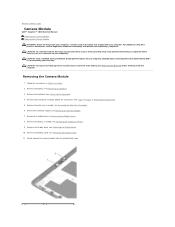
... the Display Panel). 11. Remove the battery (see Removing the Palm Rest Assembly). 6. Removing the Camera Module 1. Remove the palm rest assembly (see Removing the Battery). 3. Gently remove the camera module from step 4 to Contents Page Camera Module Dell™ Inspiron™ 1018 Service ...Manual Removing the Camera Module Replacing the Camera Module WARNING: Before working inside your computer, read the safety information that is not authorized by Dell™ is not covered by periodically touching...
... the Display Panel). 11. Remove the battery (see Removing the Palm Rest Assembly). 6. Removing the Camera Module 1. Remove the palm rest assembly (see Removing the Battery). 3. Gently remove the camera module from step 4 to Contents Page Camera Module Dell™ Inspiron™ 1018 Service ...Manual Removing the Camera Module Replacing the Camera Module WARNING: Before working inside your computer, read the safety information that is not authorized by Dell™ is not covered by periodically touching...
Service Manual
Page 7
... the camera module on the computer, replace all screws and ensure that no stray screws remain inside the computer. Replace the display assembly (see Replacing the Middle Cover). 7. Replace the hard-drive assembly (follow the instructions from step 5 to Contents Page.... Replace the middle cover (see Replacing the Display Assembly). 6. Replace the keyboard (see Replacing the Display Bezel). 5. CAUTION: Before turning on the display back cover. 3. Replace the display bezel (see Replacing the Keyboard). 11. Replace the display panel (see Replacing the Battery). Replace the ...
... the camera module on the computer, replace all screws and ensure that no stray screws remain inside the computer. Replace the display assembly (see Replacing the Middle Cover). 7. Replace the hard-drive assembly (follow the instructions from step 5 to Contents Page.... Replace the middle cover (see Replacing the Display Assembly). 6. Replace the keyboard (see Replacing the Display Bezel). 5. CAUTION: Before turning on the display back cover. 3. Replace the display bezel (see Replacing the Keyboard). 11. Replace the display panel (see Replacing the Battery). Replace the ...
Service Manual
Page 9
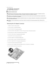
... a wrist grounding strap or by your warranty. Remove the memory module (see Removing the Display Assembly). 10. Damage due to servicing that shipped with your computer. Remove the I /O...board (see Removing the Battery). 3. Remove the Mini-Card (see Removing the Support Brackets). 11. Remove the support brackets (see Removing the Mini-Card). 8. Remove the hard-drive assembly (...in Before You Begin. 2. Back to Contents Page AC Adapter Connector Dell™ Inspiron™ 1018 Service Manual Removing the AC Adapter Connector Replacing the AC Adapter Connector WARNING...
... a wrist grounding strap or by your warranty. Remove the memory module (see Removing the Display Assembly). 10. Damage due to servicing that shipped with your computer. Remove the I /O...board (see Removing the Battery). 3. Remove the Mini-Card (see Removing the Support Brackets). 11. Remove the support brackets (see Removing the Mini-Card). 8. Remove the hard-drive assembly (...in Before You Begin. 2. Back to Contents Page AC Adapter Connector Dell™ Inspiron™ 1018 Service Manual Removing the AC Adapter Connector Replacing the AC Adapter Connector WARNING...
Service Manual
Page 10
...). 12. Replace the support brackets (see Replacing the Mini-Card). 9. Replace the Mini-Card (see Replacing the Support Brackets). 6. Replace the hard-drive assembly (follow the instructions from step 5 to step 7 in the computer base. 3. Replace the keyboard (see Replacing the Display Assembly). 7. Replace the display assembly (see Replacing the Keyboard). 13. Replace the...
...). 12. Replace the support brackets (see Replacing the Mini-Card). 9. Replace the Mini-Card (see Replacing the Support Brackets). 6. Replace the hard-drive assembly (follow the instructions from step 5 to step 7 in the computer base. 3. Replace the keyboard (see Replacing the Display Assembly). 7. Replace the display assembly (see Replacing the Keyboard). 13. Replace the...
Service Manual
Page 11
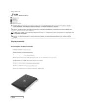
...Display Dell™ Inspiron™ 1018 Service Manual Display Assembly Display Bezel Display Panel Display Cable Display Panel Brackets WARNING: Before working inside your computer, read the safety information that shipped with your computer. For additional safety best practices information, see Removing the Battery). 3. Remove the screw that is not authorized by Dell..., remove the main battery (see Removing the Battery) before working inside the computer. Display Assembly Removing the Display Assembly 1. Remove the hard-drive assembly (follow the instructions from step 4 to the...
...Display Dell™ Inspiron™ 1018 Service Manual Display Assembly Display Bezel Display Panel Display Cable Display Panel Brackets WARNING: Before working inside your computer, read the safety information that shipped with your computer. For additional safety best practices information, see Removing the Battery). 3. Remove the screw that is not authorized by Dell..., remove the main battery (see Removing the Battery) before working inside the computer. Display Assembly Removing the Display Assembly 1. Remove the hard-drive assembly (follow the instructions from step 4 to the...
Service Manual
Page 12
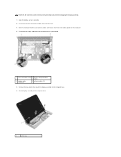
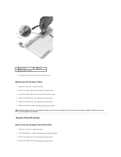
... routing guides on the system board. 1 Mini-Card cable routing 2 display cable grounding screw 3 display cable connector 4 antenna cables (2) 13. Lift the display assembly off the computer base. 1 screws (2) Remove the two screws that secure the display assembly to prevent damaging the display assembly. 9. Note the routing of the Mini-Card antenna cables and remove them from...
... routing guides on the system board. 1 Mini-Card cable routing 2 display cable grounding screw 3 display cable connector 4 antenna cables (2) 13. Lift the display assembly off the computer base. 1 screws (2) Remove the two screws that secure the display assembly to prevent damaging the display assembly. 9. Note the routing of the Mini-Card antenna cables and remove them from...
Service Manual
Page 13
... Before You Begin. 2. Close the display and replace the screw that secures the display assembly to the Mini-Card (see Replacing the Mini-Card). 7. CAUTION: Before turning on the computer base. 6. Connect the display cable to the display assembly. Remove the two screws that cover the display bezel screws. 4. Replacing the Display Assembly 1. Replace the memory module (see...
... Before You Begin. 2. Close the display and replace the screw that secures the display assembly to the Mini-Card (see Replacing the Mini-Card). 7. CAUTION: Before turning on the computer base. 6. Connect the display cable to the display assembly. Remove the two screws that cover the display bezel screws. 4. Replacing the Display Assembly 1. Replace the memory module (see...
Service Manual
Page 14
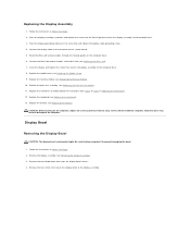
... the two rubber pads that no stray screws remain inside edge of the display bezel. 6. Display Panel Removing the Display Panel 1. Remove the display assembly (see Replacing the Display Assembly). Remove the display bezel (see Removing the Display Bezel). 4. Align the display bezel over the display panel, and gently snap it into place. 3. Disconnect the camera cable from the...
... the two rubber pads that no stray screws remain inside edge of the display bezel. 6. Display Panel Removing the Display Panel 1. Remove the display assembly (see Replacing the Display Assembly). Remove the display bezel (see Removing the Display Bezel). 4. Align the display bezel over the display panel, and gently snap it into place. 3. Disconnect the camera cable from the...
Service Manual
Page 15
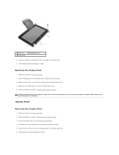
... result in Before You Begin. 2. Failure to the connector on the display panel. Remove the display bezel (see Removing the Display Assembly). 3. Pull the pull-tab to the display back cover. 5. Remove the display assembly (see Removing the Display Bezel). 4. Replace the display assembly (see Replacing the Display Assembly). Follow the instructions in Before You Begin. 2. Turn the...
... result in Before You Begin. 2. Failure to the connector on the display panel. Remove the display bezel (see Removing the Display Assembly). 3. Pull the pull-tab to the display back cover. 5. Remove the display assembly (see Removing the Display Bezel). 4. Replace the display assembly (see Replacing the Display Assembly). Follow the instructions in Before You Begin. 2. Turn the...
Service Manual
Page 16
Replacing the Display Cable 1. Replace the display bezel (see Removing the Display Panel). Remove the display panel (see Replacing the Display Bezel). 6. CAUTION: Before turning on the display panel. 4. Display Panel Brackets Removing the Display Panel Brackets 1. Remove the display assembly (see Removing the Display Bezel). 4. Remove the display bezel (see Removing the Display Assembly). 3. Connect the display cable to the computer. Failure to...
Replacing the Display Cable 1. Replace the display bezel (see Removing the Display Panel). Remove the display panel (see Replacing the Display Bezel). 6. CAUTION: Before turning on the display panel. 4. Display Panel Brackets Removing the Display Panel Brackets 1. Remove the display assembly (see Removing the Display Bezel). 4. Remove the display bezel (see Removing the Display Assembly). 3. Connect the display cable to the computer. Failure to...
Service Manual
Page 17
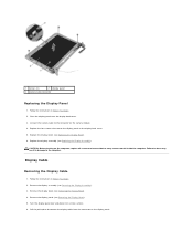
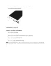
... You Begin. 2. Remove the four screws (two on each side) that no stray screws remain inside the computer. Remove the display panel brackets off the display panel. 1 display panel brackets (2) 2 screws (4) Replacing the Display Panel Brackets 1. Replace the display assembly (see Replacing the Display Assembly). 5. Replace the four screws (two on each side) that secure the...
... You Begin. 2. Remove the four screws (two on each side) that no stray screws remain inside the computer. Remove the display panel brackets off the display panel. 1 display panel brackets (2) 2 screws (4) Replacing the Display Panel Brackets 1. Replace the display assembly (see Replacing the Display Assembly). 5. Replace the four screws (two on each side) that secure the...
Service Manual
Page 22
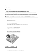
... instructions in Removing the Hard Drive). 5. Remove the palm rest assembly (see the Regulatory Compliance Homepage at www.dell.com/regulatory_compliance. Remove the display assembly (see Removing the Keyboard). 4. Remove the grounding screw that secures the I /O Board 1. Remove the ... the Display Assembly). 9. Disconnect the I/O board cable from step 4 to step 6 in Before You Begin. 2. Remove the battery (see Removing the Middle Cover). 8. Remove the middle cover (see Removing the Battery). 3. Back to Contents Page I/O Board Dell™ Inspiron™ 1018 Service Manual...
... instructions in Removing the Hard Drive). 5. Remove the palm rest assembly (see the Regulatory Compliance Homepage at www.dell.com/regulatory_compliance. Remove the display assembly (see Removing the Keyboard). 4. Remove the grounding screw that secures the I /O Board 1. Remove the ... the Display Assembly). 9. Disconnect the I/O board cable from step 4 to step 6 in Before You Begin. 2. Remove the battery (see Removing the Middle Cover). 8. Remove the middle cover (see Removing the Battery). 3. Back to Contents Page I/O Board Dell™ Inspiron™ 1018 Service Manual...
Service Manual
Page 23
... the middle cover (see Replacing the Support Brackets). 6. Connect the I/O board cable to step 7 in Replacing the Hard Drive). 11. Replace the display assembly (see Replacing the Memory Module). 9. Replace the hard-drive assembly (follow the instructions from step 5 to the connector on the I /O board...replace the grounding screw. 5. Failure to do so may result in Before You Begin. 2. Replace the memory module (see Replacing the Display Assembly). 7. Replace the keyboard (see Replacing the Battery). Align the connectors on the computer, replace all screws and ensure that no ...
... the middle cover (see Replacing the Support Brackets). 6. Connect the I/O board cable to step 7 in Replacing the Hard Drive). 11. Replace the display assembly (see Replacing the Memory Module). 9. Replace the hard-drive assembly (follow the instructions from step 5 to the connector on the I /O board...replace the grounding screw. 5. Failure to do so may result in Before You Begin. 2. Replace the memory module (see Replacing the Display Assembly). 7. Replace the keyboard (see Replacing the Battery). Align the connectors on the computer, replace all screws and ensure that no ...
Service Manual
Page 24
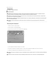
For additional safety best practices information, see Removing the Battery). 3. Follow the instructions in scratching the display panel. Remove the three screws that is not authorized by Dell™ is not covered by periodically touching an unpainted metal surface (such as possible. 5. Removing the Keyboard...the display as far as a connector on the palm rest. Carefully lift the keyboard and slide the keyboard tabs out of the slots on your warranty. Be careful when removing and handling the keyboard. Back to Contents Page Keyboard Dell™ Inspiron™ 1018 Service...
For additional safety best practices information, see Removing the Battery). 3. Follow the instructions in scratching the display panel. Remove the three screws that is not authorized by Dell™ is not covered by periodically touching an unpainted metal surface (such as possible. 5. Removing the Keyboard...the display as far as a connector on the palm rest. Carefully lift the keyboard and slide the keyboard tabs out of the slots on your warranty. Be careful when removing and handling the keyboard. Back to Contents Page Keyboard Dell™ Inspiron™ 1018 Service...
Service Manual
Page 41
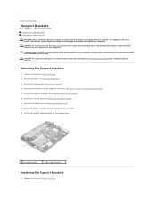
... the instructions in Before You Begin. Remove the display assembly (see Removing the Memory Module) 7. CAUTION: Only a certified service technician should perform repairs on your computer. Damage due to servicing that shipped with your computer). Back to Contents Page Support Brackets Dell™ Inspiron™ 1018 Service Manual Removing the Support Brackets Replacing the...
... the instructions in Before You Begin. Remove the display assembly (see Removing the Memory Module) 7. CAUTION: Only a certified service technician should perform repairs on your computer. Damage due to servicing that shipped with your computer). Back to Contents Page Support Brackets Dell™ Inspiron™ 1018 Service Manual Removing the Support Brackets Replacing the...
Service Manual
Page 42
Replace the middle cover (see Replacing the Battery). Replace the battery (see Replacing the Middle Cover). 5. Replace the palm rest assembly (see Replacing the Display Assembly). 4. Replace the display assembly (see Replacing the Palm Rest Assembly). 7. Failure to do so may result in damage to step 7 in Replacing the Hard Drive). 8. Replace the...
Replace the middle cover (see Replacing the Battery). Replace the battery (see Replacing the Middle Cover). 5. Replace the palm rest assembly (see Replacing the Display Assembly). 4. Replace the display assembly (see Replacing the Palm Rest Assembly). 7. Failure to do so may result in damage to step 7 in Replacing the Hard Drive). 8. Replace the...
Service Manual
Page 43
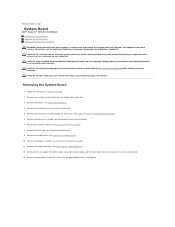
...components and cards by your computer). Remove the battery (see Removing the Mini-Card). 9. Remove the Mini-Card (see Removing the Battery). 4. Remove the display assembly (see the Regulatory Compliance Homepage at www.dell.com/regulatory_compliance. Disconnect the AC adapter connector cable, status lights board ... the system board. 13. Follow the instructions in Before You Begin. 2. Back to Contents Page System Board Dell™ Inspiron™ 1018 Service Manual Removing the System Board Replacing the System Board Entering the Service Tag in the BIOS WARNING: Before working...
...components and cards by your computer). Remove the battery (see Removing the Mini-Card). 9. Remove the Mini-Card (see Removing the Battery). 4. Remove the display assembly (see the Regulatory Compliance Homepage at www.dell.com/regulatory_compliance. Disconnect the AC adapter connector cable, status lights board ... the system board. 13. Follow the instructions in Before You Begin. 2. Back to Contents Page System Board Dell™ Inspiron™ 1018 Service Manual Removing the System Board Replacing the System Board Entering the Service Tag in the BIOS WARNING: Before working...
Service Manual
Page 44
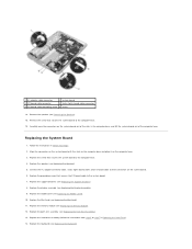
...). 9. Replace the screw that secures the system board to the computer base. 16. Replace the display assembly (see Removing the Speaker). 15. Replace the memory module (see Replacing the Mini-Card). 11. Replace the grounding screw that secures the I /O board cable grounding screw 6 screw 14...Drive). 14. Align the connectors on the system board with the slots on the computer base and place it on the system board. 6. Replace the Mini-Card (see Replacing the Memory Module). 12. 1 AC adapter cable connector 2 system board 3 I/O board cable connector 4 status lights board cable ...
...). 9. Replace the screw that secures the system board to the computer base. 16. Replace the display assembly (see Removing the Speaker). 15. Replace the memory module (see Replacing the Mini-Card). 11. Replace the grounding screw that secures the I /O board cable grounding screw 6 screw 14...Drive). 14. Align the connectors on the system board with the slots on the computer base and place it on the system board. 6. Replace the Mini-Card (see Replacing the Memory Module). 12. 1 AC adapter cable connector 2 system board 3 I/O board cable connector 4 status lights board cable ...


