
Service Manual
Page 1
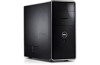
...indicates a potential for property damage, personal injury, or death. Microsoft and Windows are trademarks of Dell Inc. A00 Trademarks used in this text: Dell, the DELL logo, and Inspiron are either the entities claiming the marks and names or their products. Reproduction of Microsoft Corporation in... this document to refer to hardware or loss of your computer. Dell™ Inspiron™ 535/537/545/546 Service Manual Technical Overview Before You Begin Computer Cover Front Bezel Memory PCI and PCI Express ...
...indicates a potential for property damage, personal injury, or death. Microsoft and Windows are trademarks of Dell Inc. A00 Trademarks used in this text: Dell, the DELL logo, and Inspiron are either the entities claiming the marks and names or their products. Reproduction of Microsoft Corporation in... this document to refer to hardware or loss of your computer. Dell™ Inspiron™ 535/537/545/546 Service Manual Technical Overview Before You Begin Computer Cover Front Bezel Memory PCI and PCI Express ...
Service Manual
Page 2
...hold the power button for removing and installing the components in reverse order. Back to Contents Page Before You Begin Dell™ Inspiron™ 535/537/545/546 Service Manual Technical Specifications Recommended Tools Turning Off Your Computer Safety Instructions This chapter provides procedures for ... down the operating system. 2. If your own personal safety. l A component can be replaced or-if purchased separately-installed by Dell is flat and clean to ensure your computer and attached devices did not automatically turn off . WARNING: Before working inside your computer...
...hold the power button for removing and installing the components in reverse order. Back to Contents Page Before You Begin Dell™ Inspiron™ 535/537/545/546 Service Manual Technical Specifications Recommended Tools Turning Off Your Computer Safety Instructions This chapter provides procedures for ... down the operating system. 2. If your own personal safety. l A component can be replaced or-if purchased separately-installed by Dell is flat and clean to ensure your computer and attached devices did not automatically turn off . WARNING: Before working inside your computer...

Service Manual
Page 4
...Computer Cover). Rotate the bezel towards the computer until the bezel grips snap into place. 3. Back to Contents Page Front Bezel Dell™ Inspiron™ 535/537/545/546 Service Manual Removing the Front Bezel Replacing the Front Bezel WARNING: Before working inside your computer, read the safety...: To guard against electrical shock, always unplug your computer from the bezel inserts. 5. Grasp and lift the bezel grips one at www.dell.com/regulatory_compliance. Align and insert the bezel clamps in Before You Begin. 2. Back to release it from the front panel. 4. Set aside...
...Computer Cover). Rotate the bezel towards the computer until the bezel grips snap into place. 3. Back to Contents Page Front Bezel Dell™ Inspiron™ 535/537/545/546 Service Manual Removing the Front Bezel Replacing the Front Bezel WARNING: Before working inside your computer, read the safety...: To guard against electrical shock, always unplug your computer from the bezel inserts. 5. Grasp and lift the bezel grips one at www.dell.com/regulatory_compliance. Align and insert the bezel clamps in Before You Begin. 2. Back to release it from the front panel. 4. Set aside...

Service Manual
Page 5
...the card retention bracket. 4. Follow the procedures in a secure place. Back to Contents Page PCI and PCI Express Cards Dell™ Inspiron™ 535/537/545/546 Service Manual Removing the Card Retention Bracket Replacing the Card Retention Bracket Removing PCI and PCI Express Cards Replacing... information that shipped with any cover(s) (including computer covers, bezels, filler brackets, front-panel inserts, etc.) removed. Inspiron™ 535/537 1 screw 2 card retention bracket Inspiron 545/546 Lift the card retention bracket and set it aside in Before You Begin. 2.
...the card retention bracket. 4. Follow the procedures in a secure place. Back to Contents Page PCI and PCI Express Cards Dell™ Inspiron™ 535/537/545/546 Service Manual Removing the Card Retention Bracket Replacing the Card Retention Bracket Removing PCI and PCI Express Cards Replacing... information that shipped with any cover(s) (including computer covers, bezels, filler brackets, front-panel inserts, etc.) removed. Inspiron™ 535/537 1 screw 2 card retention bracket Inspiron 545/546 Lift the card retention bracket and set it aside in Before You Begin. 2.

Service Manual
Page 9
... installed. 2. Follow the procedures in system setup (see Entering System Setup) and restore the settings you attempt to Contents Page Battery Dell™ Inspiron™ 535/537/545/546 Service Manual Removing the Battery Replacing the Battery WARNING: Before working inside your computer and devices to touch the system ...pry out the battery. Insert the new battery (CR2032) into place. 2. Remove the computer cover (see the Regulatory Compliance Homepage at www.dell.com/regulatory_compliance. For additional safety best practices information, see Removing the Computer Cover). 4.
... installed. 2. Follow the procedures in system setup (see Entering System Setup) and restore the settings you attempt to Contents Page Battery Dell™ Inspiron™ 535/537/545/546 Service Manual Removing the Battery Replacing the Battery WARNING: Before working inside your computer and devices to touch the system ...pry out the battery. Insert the new battery (CR2032) into place. 2. Remove the computer cover (see the Regulatory Compliance Homepage at www.dell.com/regulatory_compliance. For additional safety best practices information, see Removing the Computer Cover). 4.

Service Manual
Page 11
...away from the electrical outlet before removing the cover. Ensure that sufficient space exists to Contents Page Computer Cover Dell™ Inspiron™ 535/537/545/546 Service Manual Removing the Computer Cover Replacing the Computer Cover WARNING: Before working inside the computer.... the computer cover down and slide it up . 3. For additional safety best practices information, see the Regulatory Compliance Homepage at www.dell.com/regulatory_compliance. Replace the two screws that shipped with your computer, read the safety information that secure the computer cover, using a ...
...away from the electrical outlet before removing the cover. Ensure that sufficient space exists to Contents Page Computer Cover Dell™ Inspiron™ 535/537/545/546 Service Manual Removing the Computer Cover Replacing the Computer Cover WARNING: Before working inside the computer.... the computer cover down and slide it up . 3. For additional safety best practices information, see the Regulatory Compliance Homepage at www.dell.com/regulatory_compliance. Replace the two screws that shipped with your computer, read the safety information that secure the computer cover, using a ...

Service Manual
Page 13
...Dell™ Inspiron™ 535/537/545/546 Service Manual Removing the Processor Replacing the Processor WARNING: Before working inside your computer, read the safety information that shipped with hardware removal and replacement. For technical service, see the Regulatory Compliance Homepage at www.dell...removing the cover. WARNING: To guard against electrical shock, always unplug your computer. Inspiron™ 535/537/545 1 processor cover 2 processor 3 socket 4 release lever Inspiron 546 For additional safety best practices information, see the Setup Guide. Removing the ...
...Dell™ Inspiron™ 535/537/545/546 Service Manual Removing the Processor Replacing the Processor WARNING: Before working inside your computer, read the safety information that shipped with hardware removal and replacement. For technical service, see the Regulatory Compliance Homepage at www.dell...removing the cover. WARNING: To guard against electrical shock, always unplug your computer. Inspiron™ 535/537/545 1 processor cover 2 processor 3 socket 4 release lever Inspiron 546 For additional safety best practices information, see the Setup Guide. Removing the ...

Service Manual
Page 14
Inspiron 535/537/545 1 front alignment notch 2 processor pin-1 indicator 3 rear alignment notch CAUTION: When replacing the processor, do not touch any of the pins inside the ...
Inspiron 535/537/545 1 front alignment notch 2 processor pin-1 indicator 3 rear alignment notch CAUTION: When replacing the processor, do not touch any of the pins inside the ...

Service Manual
Page 15
... processor. 11. Apply the new thermal grease to the top of the heat sink. 4 processor cover 7 socket Inspiron 546 5 center cover latch 8 tab 6 processor 9 release lever 1 socket 2 processor pin-1 indicator 3 processor 4 release lever 4. For Inspiron 535/537/545, orient the front and rear alignment-notches on the processor with the socket, and do...
... processor. 11. Apply the new thermal grease to the top of the heat sink. 4 processor cover 7 socket Inspiron 546 5 center cover latch 8 tab 6 processor 9 release lever 1 socket 2 processor pin-1 indicator 3 processor 4 release lever 4. For Inspiron 535/537/545, orient the front and rear alignment-notches on the processor with the socket, and do...

Service Manual
Page 16
... procedure. 1. Slide the drive out towards the back of the data cable from the hard drive. Back to Contents Page Drives Dell™ Inspiron™ 535/537/545/546 Service Manual Removing a Hard Drive Replacing a Hard Drive Removing a Media Card Reader Replacing a Media Card Reader ...removing the cover. Removing a Hard Drive CAUTION: If you begin this time, disconnect the other devices to install a hard drive at www.dell.com/regulatory_compliance. Remove the computer cover (see Replacing the Computer Cover). 8. For more information, see the Regulatory Compliance Homepage at a later ...
... procedure. 1. Slide the drive out towards the back of the data cable from the hard drive. Back to Contents Page Drives Dell™ Inspiron™ 535/537/545/546 Service Manual Removing a Hard Drive Replacing a Hard Drive Removing a Media Card Reader Replacing a Media Card Reader ...removing the cover. Removing a Hard Drive CAUTION: If you begin this time, disconnect the other devices to install a hard drive at www.dell.com/regulatory_compliance. Remove the computer cover (see Replacing the Computer Cover). 8. For more information, see the Regulatory Compliance Homepage at a later ...

Service Manual
Page 20
Do not try to Contents Page Fans Dell™ Inspiron™ 535/537/545/546 Service Manual Removing the Processor Fan and Heat Sink Assembly Replacing the Processor ... on the system board (see System Board Components). 4. Remove the computer cover (see the Regulatory Compliance Homepage at www.dell.com/regulatory_compliance. Loosen the four captive screws securing the processor fan and heat sink assembly and lift it has had sufficient ... removing the processor fan and heat sink assembly. Remove the processor fan and heat sink assembly. Inspiron™ 535/537/545 a. Inspiron 546 a.
Do not try to Contents Page Fans Dell™ Inspiron™ 535/537/545/546 Service Manual Removing the Processor Fan and Heat Sink Assembly Replacing the Processor ... on the system board (see System Board Components). 4. Remove the computer cover (see the Regulatory Compliance Homepage at www.dell.com/regulatory_compliance. Loosen the four captive screws securing the processor fan and heat sink assembly and lift it has had sufficient ... removing the processor fan and heat sink assembly. Remove the processor fan and heat sink assembly. Inspiron™ 535/537/545 a. Inspiron 546 a.

Service Manual
Page 21
... the one shown in place and rotate the clamp lever 180 degrees clockwise to the top of the processor fan and heat sink assembly. Inspiron 535/537/545 a. Inspiron 546 a. Ensure that you do not pinch the wires that run between the system board and the fan. 1. Replace the processor fan and heat...
... the one shown in place and rotate the clamp lever 180 degrees clockwise to the top of the processor fan and heat sink assembly. Inspiron 535/537/545 a. Inspiron 546 a. Ensure that you do not pinch the wires that run between the system board and the fan. 1. Replace the processor fan and heat...

Service Manual
Page 22
...: Do not touch the fan blades when you are removing the chassis fan. Connect your computer and devices to the fan connector on . Inspiron™ 535/537 1 screws (2) 2 chassis fan Inspiron 545/546 Follow the procedures in Before You Begin. 2. Remove the computer cover (see Replacing the Computer Cover). 6. Replace the computer cover...
...: Do not touch the fan blades when you are removing the chassis fan. Connect your computer and devices to the fan connector on . Inspiron™ 535/537 1 screws (2) 2 chassis fan Inspiron 545/546 Follow the procedures in Before You Begin. 2. Remove the computer cover (see Replacing the Computer Cover). 6. Replace the computer cover...

Service Manual
Page 24
... the cable connectors and the cable routing clips when sliding the I/O panel into the I /O panel to the chassis. 3. Back to Contents Page Front I/O Panel Dell™ Inspiron™ 535/537/545/546 Service Manual Removing the Front I/O Panel Replacing the Front I/O Panel WARNING: Before working inside your computer, read the safety information that... may result in Before You Begin. 2. Replace the screw that secures the I /O panel clamp slot. 2. Replace the bezel (see the Regulatory Compliance Homepage at www.dell.com/regulatory_compliance.
... the cable connectors and the cable routing clips when sliding the I/O panel into the I /O panel to the chassis. 3. Back to Contents Page Front I/O Panel Dell™ Inspiron™ 535/537/545/546 Service Manual Removing the Front I/O Panel Replacing the Front I/O Panel WARNING: Before working inside your computer, read the safety information that... may result in Before You Begin. 2. Replace the screw that secures the I /O panel clamp slot. 2. Replace the bezel (see the Regulatory Compliance Homepage at www.dell.com/regulatory_compliance.

Service Manual
Page 26
..., see Recommended Memory Configuration). If the memory module is difficult to remove, gently ease the memory module back and forth to Contents Page Memory Dell™ Inspiron™ 535/537/545/546 Service Manual Removing Memory Replacing Memory Recommended Memory Configuration Setting Up Dual Channel Memory Configuration WARNING: Before working inside your computer...
..., see Recommended Memory Configuration). If the memory module is difficult to remove, gently ease the memory module back and forth to Contents Page Memory Dell™ Inspiron™ 535/537/545/546 Service Manual Removing Memory Replacing Memory Recommended Memory Configuration Setting Up Dual Channel Memory Configuration WARNING: Before working inside your computer...

Service Manual
Page 27
...icon on to continue. 8. Recommended Memory Configuration While installing or replacing memory, refer to electrical outlets, and then turn them on Inspiron™ 535/537. Connect your Microsoft® Windows® desktop and click Properties. 10. Log on your computer and devices to the table...DIMM4 Setting Up Dual Channel Memory Configuration NOTE: Dual channel memory is installed correctly, check the amount of the memory module. 5. Inspiron 545 Replace the computer cover (see Replacing the Computer Cover). 7. If the message appears stating that the memory is not supported on...
...icon on to continue. 8. Recommended Memory Configuration While installing or replacing memory, refer to electrical outlets, and then turn them on Inspiron™ 535/537. Connect your Microsoft® Windows® desktop and click Properties. 10. Log on your computer and devices to the table...DIMM4 Setting Up Dual Channel Memory Configuration NOTE: Dual channel memory is installed correctly, check the amount of the memory module. 5. Inspiron 545 Replace the computer cover (see Replacing the Computer Cover). 7. If the message appears stating that the memory is not supported on...

Service Manual
Page 29
... computer cover (see the Regulatory Compliance Homepage on the side of the computer chassis. Inspiron™ 535/537 1 power supply retention snap 2 screws (4) 3 power supply 4 voltage selector switch Inspiron 545/546 Back to Contents Page Power Supply Dell™ Inspiron™ 535/537/545/546 Service Manual Removing the Power Supply Replacing the Power Supply WARNING...
... computer cover (see the Regulatory Compliance Homepage on the side of the computer chassis. Inspiron™ 535/537 1 power supply retention snap 2 screws (4) 3 power supply 4 voltage selector switch Inspiron 545/546 Back to Contents Page Power Supply Dell™ Inspiron™ 535/537/545/546 Service Manual Removing the Power Supply Replacing the Power Supply WARNING...

Service Manual
Page 31
... Help Field - This field appears below the Option Field and lists keys and their functions within the active system setup field. Inspiron 535/537 System Info System BIOS Info Asset Tag Service Tag Processor Type Processor Level 2 Cache Displays the computer model number. Displays ...section may not appear, or may result when a key on your computer to work incorrectly. Back to Contents Page System Setup Dell™ Inspiron™ 535/537/545/546 Service Manual Overview Entering System Setup Clearing Forgotten Passwords Clearing CMOS Settings Flashing the BIOS Overview Use System Setup: ...
... Help Field - This field appears below the Option Field and lists keys and their functions within the active system setup field. Inspiron 535/537 System Info System BIOS Info Asset Tag Service Tag Processor Type Processor Level 2 Cache Displays the computer model number. Displays ...section may not appear, or may result when a key on your computer to work incorrectly. Back to Contents Page System Setup Dell™ Inspiron™ 535/537/545/546 Service Manual Overview Entering System Setup Clearing Forgotten Passwords Clearing CMOS Settings Flashing the BIOS Overview Use System Setup: ...

Service Manual
Page 36
...Passwords WARNING: Before working inside your device is to be bootable. Remove the computer cover (see Entering System Setup). 2. Inspiron 535/537 Inspiron 545 To make sure your computer, read the safety information that is bootable, check the device documentation. Changing Boot Sequence ...2. NOTE: Write down -arrow keys to access the menu. For additional safety best practices information, see the Regulatory Compliance Homepage at www.dell.com/regulatory_compliance. 1. Press plus (+) or minus (-) to a USB memory key, highlight USB Flash Device and press . NOTE: The ...
...Passwords WARNING: Before working inside your device is to be bootable. Remove the computer cover (see Entering System Setup). 2. Inspiron 535/537 Inspiron 545 To make sure your computer, read the safety information that is bootable, check the device documentation. Changing Boot Sequence ...2. NOTE: Write down -arrow keys to access the menu. For additional safety best practices information, see the Regulatory Compliance Homepage at www.dell.com/regulatory_compliance. 1. Press plus (+) or minus (-) to a USB memory key, highlight USB Flash Device and press . NOTE: The ...

Service Manual
Page 38
Inspiron 535/537 Inspiron 545 Inspiron 546 4. Replace the computer cover (see Replacing the Computer Cover).
Inspiron 535/537 Inspiron 545 Inspiron 546 4. Replace the computer cover (see Replacing the Computer Cover).

