
Inspiron 24 3000 Setup and Specifications
Page 8
Connect to a secured wireless network, enter the password for Windows updates. NOTE: If connecting to a network for the wireless network access when prompted. - When setting up, Dell recommends that you: - If connected to the internet, create an offline account. - For more information about installing and configuring Ubuntu, see the knowledge base articles SLN151664 and SLN151748 at www.dell.com/support. If not connected to the internet, sign-in with or create a Microsoft account...
Connect to a secured wireless network, enter the password for Windows updates. NOTE: If connecting to a network for the wireless network access when prompted. - When setting up, Dell recommends that you: - If connected to the internet, create an offline account. - For more information about installing and configuring Ubuntu, see the knowledge base articles SLN151664 and SLN151748 at www.dell.com/support. If not connected to the internet, sign-in with or create a Microsoft account...

Inspiron 24 3000 Setup and Specifications
Page 9
... create a recovery drive to renew or upgrade your warranty. For more information about using Dell Digital Delivery, see the SupportAssist documentation at www.dell.com/support. Dell Digital Delivery Download software applications, which are purchased but not pre-installed on your computer with the operating system. 6 Locate and use Dell apps from the Windows Start menu-Recommended Table 1. It also notifies you about your computer's hardware and software. SupportAssist Pro...
... create a recovery drive to renew or upgrade your warranty. For more information about using Dell Digital Delivery, see the SupportAssist documentation at www.dell.com/support. Dell Digital Delivery Download software applications, which are purchased but not pre-installed on your computer with the operating system. 6 Locate and use Dell apps from the Windows Start menu-Recommended Table 1. It also notifies you about your computer's hardware and software. SupportAssist Pro...

Inspiron 24 3000 Setup and Specifications
Page 10
... following steps may occur with a minimum capacity of Windows installed. A message appears, indicating that may vary depending on the version of 16 GB is displayed. 5 Select Back up to an hour to continue. An empty USB flash drive with Windows. The Recovery Drive window is required to create the recovery drive. Create a USB recovery drive for latest instructions. 1 Connect the USB flash drive to your product's Service Manual at www.dell.com/support/manuals. 10
... following steps may occur with a minimum capacity of Windows installed. A message appears, indicating that may vary depending on the version of 16 GB is displayed. 5 Select Back up to an hour to continue. An empty USB flash drive with Windows. The Recovery Drive window is required to create the recovery drive. Create a USB recovery drive for latest instructions. 1 Connect the USB flash drive to your product's Service Manual at www.dell.com/support/manuals. 10

Inspiron 24 3000 Setup and Specifications
Page 14
... speeds up to your computer and access warranty information. 2 Power-adapter port Connect a power adapter to provide power to 480 Mbps. 5 HDMI-in your computer. 3 Network port (with lights) Connect an Ethernet (RJ45) cable from a router or a broadband modem for network or Internet access. Back view 1 Service Tag label The Service Tag is a unique alphanumeric identifier that enables Dell service technicians to identify the hardware components in port 14 Back Figure 4. The two lights next to the connector...
... speeds up to your computer and access warranty information. 2 Power-adapter port Connect a power adapter to provide power to 480 Mbps. 5 HDMI-in your computer. 3 Network port (with lights) Connect an Ethernet (RJ45) cable from a router or a broadband modem for network or Internet access. Back view 1 Service Tag label The Service Tag is a unique alphanumeric identifier that enables Dell service technicians to identify the hardware components in port 14 Back Figure 4. The two lights next to the connector...

Inspiron 24 3000 Setup and Specifications
Page 19
Ports and connectors External: Network One RJ45 port USB • Two USB 2.0 ports • Two USB 3.0 ports Audio/Video • One HDMI-in port • One audio line-out port • One headset port Table 6. Ports and connectors Internal: M.2 card One M.2 slot for WLAN and Bluetooth Communications Table 7. Communications Ethernet Wireless 10/100 Mbps Ethernet controller integrated on system board • Wi-Fi 802.11ac 19 Memory Table 4. Memory Slots Two SODIMM slots Type DDR4 Speed Up to 2133 MHz Configurations supported 2 GB, 4 GB, 6 GB, 8 GB...
Ports and connectors External: Network One RJ45 port USB • Two USB 2.0 ports • Two USB 3.0 ports Audio/Video • One HDMI-in port • One audio line-out port • One headset port Table 6. Ports and connectors Internal: M.2 card One M.2 slot for WLAN and Bluetooth Communications Table 7. Communications Ethernet Wireless 10/100 Mbps Ethernet controller integrated on system board • Wi-Fi 802.11ac 19 Memory Table 4. Memory Slots Two SODIMM slots Type DDR4 Speed Up to 2133 MHz Configurations supported 2 GB, 4 GB, 6 GB, 8 GB...

Inspiron 24 3000 Setup and Specifications
Page 21
....50 in) 543 mm (21.38 in) 604.52 mm (23.80 in -1 slot Cards supported • SD card • MultiMediaCard (MMC) • SD Extended Capacity (SDXC) card • SD High Capacity (SDHC) card Display Table 12. Media-card reader Type One 4-in ) 60 Hz 21 Storage Interface Hard drive Optical drive • SATA 3 Gbps for optical drive • SATA 6 Gbps for hard drive One 2.5-inch drive One 9.5-mm DVD+/-RW drive (optional) Media-card reader Table 11.
....50 in) 543 mm (21.38 in) 604.52 mm (23.80 in -1 slot Cards supported • SD card • MultiMediaCard (MMC) • SD Extended Capacity (SDXC) card • SD High Capacity (SDHC) card Display Table 12. Media-card reader Type One 4-in ) 60 Hz 21 Storage Interface Hard drive Optical drive • SATA 3 Gbps for optical drive • SATA 6 Gbps for hard drive One 2.5-inch drive One 9.5-mm DVD+/-RW drive (optional) Media-card reader Table 11.

Inspiron 24 3000 Setup and Specifications
Page 25
...; Operating system • Setting up and using your product • Data backup • Troubleshooting and diagnostics • Factory and system restore • BIOS information Resource location To locate the Me and My Dell relevant to your product, identify your product through one of the following: • Select Detect Product. • Locate your product through the drop-down menu under View Products. • Enter the Service...
...; Operating system • Setting up and using your product • Data backup • Troubleshooting and diagnostics • Factory and system restore • BIOS information Resource location To locate the Me and My Dell relevant to your product, identify your product through one of the following: • Select Detect Product. • Locate your product through the drop-down menu under View Products. • Enter the Service...

Inspiron 24 3000 Service Manual
Page 4
Removing the optical drive 26 Prerequisites...26 Procedure...26 Replacing the optical drive 29 Procedure...29 Post-requisites 29 Removing the hard drive 30 Prerequisites...30 Procedure...30 Replacing the hard drive 33 Procedure...33 Post-requisites 33 Removing the memory modules 34 Prerequisites...34 Procedure...34 Replacing the memory modules 36 Procedure...36 Post-requisites 37 Removing the wireless card 38 Prerequisites...38 Procedure...38 Replacing the wireless card 40 Procedure...40 Post-requisites 41 4
Removing the optical drive 26 Prerequisites...26 Procedure...26 Replacing the optical drive 29 Procedure...29 Post-requisites 29 Removing the hard drive 30 Prerequisites...30 Procedure...30 Replacing the hard drive 33 Procedure...33 Post-requisites 33 Removing the memory modules 34 Prerequisites...34 Procedure...34 Replacing the memory modules 36 Procedure...36 Post-requisites 37 Removing the wireless card 38 Prerequisites...38 Procedure...38 Replacing the wireless card 40 Procedure...40 Post-requisites 41 4

Inspiron 24 3000 Service Manual
Page 9
... you are using a different operating system, see the documentation of your operating system for 5 seconds to avoid scratches on your computer. - Before working inside your computer NOTE: The images in this document may differ from your computer depending on , from your computer. 6 Remove any media card and optical disc from your computer. 5 Disconnect all cables such as keyboard, mouse, monitor, and so on the configuration you...
... you are using a different operating system, see the documentation of your operating system for 5 seconds to avoid scratches on your computer. - Before working inside your computer NOTE: The images in this document may differ from your computer depending on , from your computer. 6 Remove any media card and optical disc from your computer. 5 Disconnect all cables such as keyboard, mouse, monitor, and so on the configuration you...

Inspiron 24 3000 Service Manual
Page 10
... cables, keep them by your personal safety. WARNING: Before working inside your computer, read the safety information that shipped with your computer. CAUTION: To avoid damaging the computer, ensure that the ports and connectors are correctly oriented and aligned. CAUTION: Press and eject any connector pins. Safety instructions Use the following safety guidelines to protect your computer from the media-card reader...
... cables, keep them by your personal safety. WARNING: Before working inside your computer, read the safety information that shipped with your computer. CAUTION: To avoid damaging the computer, ensure that the ports and connectors are correctly oriented and aligned. CAUTION: Press and eject any connector pins. Safety instructions Use the following safety guidelines to protect your computer from the media-card reader...

Inspiron 24 3000 Service Manual
Page 11
... the list of screws that are used for securing different components to Easel stand bracket back cover Screw type Quantity M4x8 2 Screw image Pedestal stand display-panel M4x8 4 base Optical-drive Display- M3x5 1 assembly assembly base Hard drive Hard-drive M3x5 3 bracket Wireless card Wireless-card M2x2.5 1 bracket Heat-sink Display- M3x5 2 assembly base System board Display- M3x5 1 assembly assembly base Optical-drive Optical drive M2x2.5 1 bracket Hard-drive Display- Component Secured to the palm rest and keyboard assembly...
... the list of screws that are used for securing different components to Easel stand bracket back cover Screw type Quantity M4x8 2 Screw image Pedestal stand display-panel M4x8 4 base Optical-drive Display- M3x5 1 assembly assembly base Hard drive Hard-drive M3x5 3 bracket Wireless card Wireless-card M2x2.5 1 bracket Heat-sink Display- M3x5 2 assembly base System board Display- M3x5 1 assembly assembly base Optical-drive Optical drive M2x2.5 1 bracket Hard-drive Display- Component Secured to the palm rest and keyboard assembly...

Inspiron 24 3000 Service Manual
Page 13
After working inside your computer CAUTION: Leaving stray or loose screws inside your computer may severely damage your computer. 1 Replace all screws and ensure that no stray screws remain inside your computer. 2 Connect any external devices, peripherals, or cables you removed before working on your computer. 3 Replace any media cards, discs, or any other parts that you removed before working on your computer. 4 Connect your computer and all attached devices to their electrical outlets. 5 Turn on your computer. 13
After working inside your computer CAUTION: Leaving stray or loose screws inside your computer may severely damage your computer. 1 Replace all screws and ensure that no stray screws remain inside your computer. 2 Connect any external devices, peripherals, or cables you removed before working on your computer. 3 Replace any media cards, discs, or any other parts that you removed before working on your computer. 4 Connect your computer and all attached devices to their electrical outlets. 5 Turn on your computer. 13
Inspiron 24 3000 Service Manual
Page 14
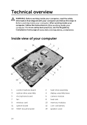
... working inside your computer, read the safety information that shipped with your computer and follow the instructions in Before working inside your computer. After working inside your computer, follow the steps in After working inside your computer 1 control-buttons board 3 optical-drive assembly 5 microphone board 7 fan 9 wireless card 11 system board 13 VESA-mount bracket 14 2 hard-drive assembly 4 display-assembly base 6 camera module 8 heat sink 10 memory modules 12 coin-cell battery 14 speaker cover...
... working inside your computer, read the safety information that shipped with your computer and follow the instructions in Before working inside your computer. After working inside your computer, follow the steps in After working inside your computer 1 control-buttons board 3 optical-drive assembly 5 microphone board 7 fan 9 wireless card 11 system board 13 VESA-mount bracket 14 2 hard-drive assembly 4 display-assembly base 6 camera module 8 heat sink 10 memory modules 12 coin-cell battery 14 speaker cover...

Inspiron 24 3000 Service Manual
Page 16
13 display-cable connector (LVDS) 14 hard-drive data cable connector (SATA_HDD) 15 optical-drive cable connector (SATA_ODD) 16 hard-drive and optical-drive power cable connector (SATAP1) 17 fan-cable connector (FAN_CPU) 16
13 display-cable connector (LVDS) 14 hard-drive data cable connector (SATA_HDD) 15 optical-drive cable connector (SATA_ODD) 16 hard-drive and optical-drive power cable connector (SATAP1) 17 fan-cable connector (FAN_CPU) 16
Inspiron 24 3000 Service Manual
Page 30
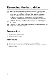
... Regulatory Compliance home page at www.dell.com/regulatory_compliance. CAUTION: Hard drives are fragile. Exercise care when handling the hard drive. Prerequisites 1 Remove the stand assembly. 2 Remove the back cover. Procedure 1 Disconnect the power and data cable from the hard drive. 2 Remove the screw that shipped with your computer and follow the instructions in sleep or on state. After working inside your computer, follow the steps in...
... Regulatory Compliance home page at www.dell.com/regulatory_compliance. CAUTION: Hard drives are fragile. Exercise care when handling the hard drive. Prerequisites 1 Remove the stand assembly. 2 Remove the back cover. Procedure 1 Disconnect the power and data cable from the hard drive. 2 Remove the screw that shipped with your computer and follow the instructions in sleep or on state. After working inside your computer, follow the steps in...
Inspiron 24 3000 Service Manual
Page 33
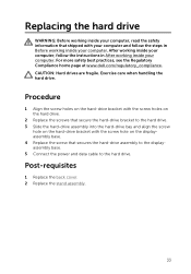
... at www.dell.com/regulatory_compliance. Exercise care when handling the hard drive. Replacing the hard drive WARNING: Before working inside your computer, read the safety information that shipped with the screw hole on the hard-drive bracket with your computer and follow the instructions in Before working inside your computer. After working inside your computer, follow the steps in After working inside your computer. CAUTION: Hard drives are fragile...
... at www.dell.com/regulatory_compliance. Exercise care when handling the hard drive. Replacing the hard drive WARNING: Before working inside your computer, read the safety information that shipped with the screw hole on the hard-drive bracket with your computer and follow the instructions in Before working inside your computer. After working inside your computer, follow the steps in After working inside your computer. CAUTION: Hard drives are fragile...
Inspiron 24 3000 Service Manual
Page 57
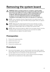
... board. Prerequisites 1 Remove the stand assembly. 2 Remove the back cover. 3 Remove the heat sink. 4 Remove the wireless card. Procedure 1 Disconnect the speaker, touch-control board, hard-drive cable, opticaldrive cable, hard-drive and optical-drive power, fan, and microphone and camera cables from its connectors on the system board. 2 Lift the latches and disconnect the control-buttons board and display cables from the system board, note the location of the connectors so that shipped with your computer and follow the instructions in After working inside...
... board. Prerequisites 1 Remove the stand assembly. 2 Remove the back cover. 3 Remove the heat sink. 4 Remove the wireless card. Procedure 1 Disconnect the speaker, touch-control board, hard-drive cable, opticaldrive cable, hard-drive and optical-drive power, fan, and microphone and camera cables from its connectors on the system board. 2 Lift the latches and disconnect the control-buttons board and display cables from the system board, note the location of the connectors so that shipped with your computer and follow the instructions in After working inside...
Inspiron 24 3000 Service Manual
Page 60
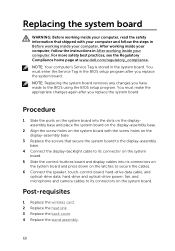
... instructions in Before working inside your computer. You must make the appropriate changes again after you replace the system board. NOTE: Your computer's Service Tag is stored in the BIOS setup program after you have made to its connectors on the system board and press down on the latches to secure the cables. 6 Connect the speaker, touch-control board, hard-drive data cable, and optical-drive data, hard-drive and optical-drive power, fan, and microphone and camera cables...
... instructions in Before working inside your computer. You must make the appropriate changes again after you replace the system board. NOTE: Your computer's Service Tag is stored in the BIOS setup program after you have made to its connectors on the system board and press down on the latches to secure the cables. 6 Connect the speaker, touch-control board, hard-drive data cable, and optical-drive data, hard-drive and optical-drive power, fan, and microphone and camera cables...
Inspiron 24 3000 Service Manual
Page 78
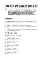
... routing guides on the display bezel. 4 Replace the screws that shipped with your computer and follow the instructions in Before working inside your computer. Post-requisites 1 Replace the control-buttons board. 2 Replace the speakers. 3 Replace the speaker cover. 4 Replace the VESA-mount bracket. 5 Replace the system board. 6 Replace the camera. 7 Replace the microphone. 8 Replace the coin-cell battery. 9 Replace the fan. 10 Replace the heat sink. 11 Replace the wireless card. 12 Replace the memory modules. 13 Replace the hard drive. 14 Replace the optical drive...
... routing guides on the display bezel. 4 Replace the screws that shipped with your computer and follow the instructions in Before working inside your computer. Post-requisites 1 Replace the control-buttons board. 2 Replace the speakers. 3 Replace the speaker cover. 4 Replace the VESA-mount bracket. 5 Replace the system board. 6 Replace the camera. 7 Replace the microphone. 8 Replace the coin-cell battery. 9 Replace the fan. 10 Replace the heat sink. 11 Replace the wireless card. 12 Replace the memory modules. 13 Replace the hard drive. 14 Replace the optical drive...

Inspiron 24 3000 Service Manual
Page 88
... chipset error 4 Memory or RAM failure 5 CMOS battery failure 6 Video card or chip failure 7 CPU failure 8 Display failure 3,3 BIOS recovery image not found (Three amber color LED flashes followed by three white color LED flashes.) 3,4 (Three amber color LED flashes followed by four white color LED flashes.) BIOS recovery image found but invalid 88 The following table shows different light patterns and what they indicate. Number of LED codes in amber color during the start in a normal mode. System diagnostic lights The computer POST (Power On Self Test...
... chipset error 4 Memory or RAM failure 5 CMOS battery failure 6 Video card or chip failure 7 CPU failure 8 Display failure 3,3 BIOS recovery image not found (Three amber color LED flashes followed by three white color LED flashes.) 3,4 (Three amber color LED flashes followed by four white color LED flashes.) BIOS recovery image found but invalid 88 The following table shows different light patterns and what they indicate. Number of LED codes in amber color during the start in a normal mode. System diagnostic lights The computer POST (Power On Self Test...


