
Specifications
Page 3
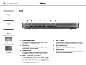
... for network or internet access. 4 USB 3.0 port with PowerShare Connect peripherals such as storage devices, printers, and so on . Provides data transfer speeds up to media cards. 7 Headset port Connect a headphone, a microphone, or a headphone and microphone combo (headset). Provides data transfer speeds up to charge your USB devices even when your computer and charge the battery. 2 HDMI port Connect a TV or another HDMI‑in enabled device. Provides video and audio output. 3 Network port Connect an Ethernet (RJ45) cable from...
... for network or internet access. 4 USB 3.0 port with PowerShare Connect peripherals such as storage devices, printers, and so on . Provides data transfer speeds up to media cards. 7 Headset port Connect a headphone, a microphone, or a headphone and microphone combo (headset). Provides data transfer speeds up to charge your USB devices even when your computer and charge the battery. 2 HDMI port Connect a TV or another HDMI‑in enabled device. Provides video and audio output. 3 Network port Connect an Ethernet (RJ45) cable from...
Specifications
Page 8
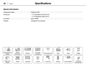
Views System Information Computer model Processor L3 cache Chipset Specifications Inspiron 7746 • 5th Generation Intel Core i5 • 5th Generation Intel Core i7 Up to 4 MB Integrated in processor Dimensions and Weight System Information Memory Ports and Connectors Communications Video Audio Storage Media-Card Reader Display Keyboard Camera Touch Pad Battery Power Adapter Computer Environment
Views System Information Computer model Processor L3 cache Chipset Specifications Inspiron 7746 • 5th Generation Intel Core i5 • 5th Generation Intel Core i7 Up to 4 MB Integrated in processor Dimensions and Weight System Information Memory Ports and Connectors Communications Video Audio Storage Media-Card Reader Display Keyboard Camera Touch Pad Battery Power Adapter Computer Environment

Specifications
Page 13
Views Audio Controller Speakers Speaker output: Average Peak Microphone Volume controls Specifications Realtek ALC3234 with Waves MaxxAudio Pro Two 2 watt 2.5 watt Digital array-microphones Program menus and keyboard shortcut keys Dimensions and Weight System Information Memory Ports and Connectors Communications Video Audio Storage Media-Card Reader Display Keyboard Camera Touch Pad Battery Power Adapter Computer Environment
Views Audio Controller Speakers Speaker output: Average Peak Microphone Volume controls Specifications Realtek ALC3234 with Waves MaxxAudio Pro Two 2 watt 2.5 watt Digital array-microphones Program menus and keyboard shortcut keys Dimensions and Weight System Information Memory Ports and Connectors Communications Video Audio Storage Media-Card Reader Display Keyboard Camera Touch Pad Battery Power Adapter Computer Environment
Specifications
Page 16
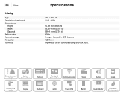
Dimensions and Weight System Information Memory Ports and Connectors Communications Video Audio Storage Media-Card Reader Display Keyboard Camera Touch Pad Battery Power Adapter Computer Environment Views Display Type Resolution (maximum) Dimensions: Height Width Diagonal Refresh rate Operating angle Pixel pitch Controls Specifications 17.3-in full HD 1920 x 1080 214.81 mm (8.46 in) 381.89 mm (15.04 in) 439.42 mm (17.30 in) 60 Hz 0 degree (closed) to 135 degrees 0.239 mm Brightness can be controlled using shortcut keys.
Dimensions and Weight System Information Memory Ports and Connectors Communications Video Audio Storage Media-Card Reader Display Keyboard Camera Touch Pad Battery Power Adapter Computer Environment Views Display Type Resolution (maximum) Dimensions: Height Width Diagonal Refresh rate Operating angle Pixel pitch Controls Specifications 17.3-in full HD 1920 x 1080 214.81 mm (8.46 in) 381.89 mm (15.04 in) 439.42 mm (17.30 in) 60 Hz 0 degree (closed) to 135 degrees 0.239 mm Brightness can be controlled using shortcut keys.
Specifications
Page 17
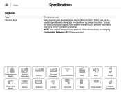
... Memory Ports and Connectors Communications Video Audio Storage Media-Card Reader Display Keyboard Camera Touch Pad Battery Power Adapter Computer Environment To perform secondary functions, press Fn and the desired key. These keys can define the primary behavior of the shortcut keys by changing Function Key Behavior in BIOS setup program. To type the alternate character, press Shift and the desired key. NOTE: You can be used to type alternate characters or to perform secondary functions. Views Keyboard Type Shortcut keys Specifications Chiclet keyboard...
... Memory Ports and Connectors Communications Video Audio Storage Media-Card Reader Display Keyboard Camera Touch Pad Battery Power Adapter Computer Environment To perform secondary functions, press Fn and the desired key. These keys can define the primary behavior of the shortcut keys by changing Function Key Behavior in BIOS setup program. To type the alternate character, press Shift and the desired key. NOTE: You can be used to type alternate characters or to perform secondary functions. Views Keyboard Type Shortcut keys Specifications Chiclet keyboard...

Service Manual
Page 3
... Begin 7 Safety Instructions 8 Recommended Tools 8 After Working Inside Your Computer 9 Removing the Battery 10 Procedure 10 Replacing the Battery 12 Procedure 12 Removing the Memory Module(s 13 Prerequisites 13 Procedure 13 Replacing the Memory Module(s 15 Procedure 15 Removing the Optical Drive 16 Prerequisites 16 Procedure 16 Replacing the Optical Drive 18 Procedure 18 Postrequisites 18 Removing the Hard Drive 19 Prerequisites 19 Procedure 19 Replacing the Hard Drive 21 Procedure 21...
... Begin 7 Safety Instructions 8 Recommended Tools 8 After Working Inside Your Computer 9 Removing the Battery 10 Procedure 10 Replacing the Battery 12 Procedure 12 Removing the Memory Module(s 13 Prerequisites 13 Procedure 13 Replacing the Memory Module(s 15 Procedure 15 Removing the Optical Drive 16 Prerequisites 16 Procedure 16 Replacing the Optical Drive 18 Procedure 18 Postrequisites 18 Removing the Hard Drive 19 Prerequisites 19 Procedure 19 Replacing the Hard Drive 21 Procedure 21...
Service Manual
Page 7
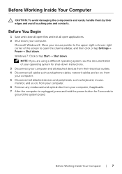
.... 6 Remove any media card and optical disc from your computer and all attached devices from their edges and avoid touching pins and contacts. Microsoft Windows 8: Move your mouse pointer to the upper-right or lower-right corner of your operating system for shut-down instructions. 3 Disconnect your computer. 5 Disconnect all open the charms sidebar, and then click or tap Settings→ Power→...
.... 6 Remove any media card and optical disc from your computer and all attached devices from their edges and avoid touching pins and contacts. Microsoft Windows 8: Move your mouse pointer to the upper-right or lower-right corner of your operating system for shut-down instructions. 3 Disconnect your computer. 5 Disconnect all open the charms sidebar, and then click or tap Settings→ Power→...
Service Manual
Page 8
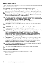
... the safety instructions that shipped with the product or at dell.com/regulatory_compliance. CAUTION: To avoid damaging the components and cards, handle them evenly aligned to avoid bending any installed card from the media-card reader. When connecting cables, make sure that is not authorized by Dell is flat and clean. After you work surface is not covered by their edges and avoid touching pins...
... the safety instructions that shipped with the product or at dell.com/regulatory_compliance. CAUTION: To avoid damaging the components and cards, handle them evenly aligned to avoid bending any installed card from the media-card reader. When connecting cables, make sure that is not authorized by Dell is flat and clean. After you work surface is not covered by their edges and avoid touching pins...
Service Manual
Page 9
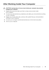
After Working Inside Your Computer CAUTION: Leaving stray or loose screws inside your computer may severely damage your computer. 1 Replace all screws and make sure that no stray screws remain inside your computer. 2 Connect any external devices, peripherals, and cables you removed before working on your computer. 3 Replace any media cards, discs, and any other part(s) that you removed before working on your computer. 4 Connect your computer and all attached devices to their electrical outlets. 5 Turn on your computer. After Working Inside Your Computer | 9
After Working Inside Your Computer CAUTION: Leaving stray or loose screws inside your computer may severely damage your computer. 1 Replace all screws and make sure that no stray screws remain inside your computer. 2 Connect any external devices, peripherals, and cables you removed before working on your computer. 3 Replace any media cards, discs, and any other part(s) that you removed before working on your computer. 4 Connect your computer and all attached devices to their electrical outlets. 5 Turn on your computer. After Working Inside Your Computer | 9
Service Manual
Page 13
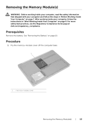
... with your computer, follow the steps in "After Working Inside Your Computer" on page 7. Prerequisites Remove the battery. After working inside your computer and follow the instructions in "Before Working Inside Your Computer" on page 9. See "Removing the Battery" on page 10. Procedure 1 Pry the memory-module cover off the computer base. 1 1 memory-module cover Removing the Memory Module(s) | 13 For more safety best practices, see the...
... with your computer, follow the steps in "After Working Inside Your Computer" on page 7. Prerequisites Remove the battery. After working inside your computer and follow the instructions in "Before Working Inside Your Computer" on page 9. See "Removing the Battery" on page 10. Procedure 1 Pry the memory-module cover off the computer base. 1 1 memory-module cover Removing the Memory Module(s) | 13 For more safety best practices, see the...
Service Manual
Page 14
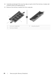
2 Carefully spread apart the securing clips on each end of the memory-module slot until the memory module pops up. 3 Remove the memory module from the computer. 1 3 2 1 memory-module slot 3 memory module 2 securing clips (2) 14 | Removing the Memory Module(s)
2 Carefully spread apart the securing clips on each end of the memory-module slot until the memory module pops up. 3 Remove the memory module from the computer. 1 3 2 1 memory-module slot 3 memory module 2 securing clips (2) 14 | Removing the Memory Module(s)

Service Manual
Page 15
... click, remove the memory module and re-install it clicks into the memory-module slot at dell.com/regulatory_compliance. Replacing the Memory Module(s) | 15 See "Replacing the Battery" on page 12. For more safety best practices, see the Regulatory Compliance home page at an angle, and press the memory module down until it . 1 2 5 3 4 1 memory-module slot 3 securing clips (2) 5 memory module 3 Replace the memory-module cover. 2 tab 4 notch Post-requisites Replace the battery. Replacing the Memory Module(s) WARNING: Before working inside...
... click, remove the memory module and re-install it clicks into the memory-module slot at dell.com/regulatory_compliance. Replacing the Memory Module(s) | 15 See "Replacing the Battery" on page 12. For more safety best practices, see the Regulatory Compliance home page at an angle, and press the memory module down until it . 1 2 5 3 4 1 memory-module slot 3 securing clips (2) 5 memory module 3 Replace the memory-module cover. 2 tab 4 notch Post-requisites Replace the battery. Replacing the Memory Module(s) WARNING: Before working inside...
Service Manual
Page 19
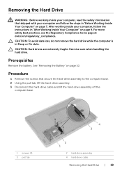
... remove the hard drive while the computer is in Sleep or On state. Prerequisites Remove the battery. Removing the Hard Drive WARNING: Before working inside your computer, read the safety information that secure the hard-drive assembly to the computer base. 2 Using the pull tab, lift the hard-drive assembly. 3 Disconnect the hard-drive cable and lift the hard-drive assembly off the computer base. 1 screws (3) 3 pull tab 4 3 2 1 2 hard-drive assembly 4 hard-drive cable Removing the Hard Drive...
... remove the hard drive while the computer is in Sleep or On state. Prerequisites Remove the battery. Removing the Hard Drive WARNING: Before working inside your computer, read the safety information that secure the hard-drive assembly to the computer base. 2 Using the pull tab, lift the hard-drive assembly. 3 Disconnect the hard-drive cable and lift the hard-drive assembly off the computer base. 1 screws (3) 3 pull tab 4 3 2 1 2 hard-drive assembly 4 hard-drive cable Removing the Hard Drive...
Service Manual
Page 23
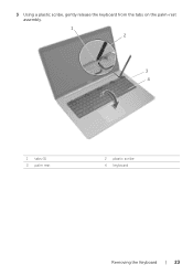
3 Using a plastic scribe, gently release the keyboard from the tabs on the palm-rest assembly. 1 2 3 4 1 tabs (5) 3 palm rest 2 plastic scribe 4 keyboard Removing the Keyboard | 23
3 Using a plastic scribe, gently release the keyboard from the tabs on the palm-rest assembly. 1 2 3 4 1 tabs (5) 3 palm rest 2 plastic scribe 4 keyboard Removing the Keyboard | 23
Service Manual
Page 30
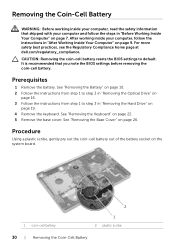
... page 22. 5 Remove the base cover. See "Removing the Battery" on page 10. 2 Follow the instructions from step 1 to step 3 in "Removing the Optical Drive" on page 16. 3 Follow the instructions from step 1 to default. CAUTION: Removing the coin-cell battery resets the BIOS settings to step 3 in "After Working Inside Your Computer" on page 19. 4 Remove the keyboard. Removing the Coin-Cell Battery WARNING: Before working inside your computer...
... page 22. 5 Remove the base cover. See "Removing the Battery" on page 10. 2 Follow the instructions from step 1 to step 3 in "Removing the Optical Drive" on page 16. 3 Follow the instructions from step 1 to default. CAUTION: Removing the coin-cell battery resets the BIOS settings to step 3 in "After Working Inside Your Computer" on page 19. 4 Remove the keyboard. Removing the Coin-Cell Battery WARNING: Before working inside your computer...
Service Manual
Page 44
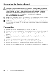
.... 6 Remove the base cover. See "Removing the Keyboard" on page 35. 44 | Removing the System Board After working inside your computer and follow the instructions in "After Working Inside Your Computer" on page 32. 8 Remove the cooling assembly. NOTE: Before disconnecting the cables from step 1 to step 3 in "Removing the Hard Drive" on page 10. 2 Remove the memory modules. See "Removing the Wireless Card" on page 9. Removing the System Board WARNING: Before working...
.... 6 Remove the base cover. See "Removing the Keyboard" on page 35. 44 | Removing the System Board After working inside your computer and follow the instructions in "After Working Inside Your Computer" on page 32. 8 Remove the cooling assembly. NOTE: Before disconnecting the cables from step 1 to step 3 in "Removing the Hard Drive" on page 10. 2 Remove the memory modules. See "Removing the Wireless Card" on page 9. Removing the System Board WARNING: Before working...
Service Manual
Page 48
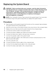
... at dell.com/regulatory_compliance. You must enter the Service Tag in the system board. Replacing the System Board WARNING: Before working inside your computer, read the safety information that secures the system board to the computer base. 4 Connect the camera cable to the system board. 5 Connect the power-adapter port cable to the system board. 6 Connect the hard-drive cable to the hard-disc connector. 7 Connect the speaker cable to the system board. 8 Slide the USB-board cable to the USB-board...
... at dell.com/regulatory_compliance. You must enter the Service Tag in the system board. Replacing the System Board WARNING: Before working inside your computer, read the safety information that secures the system board to the computer base. 4 Connect the camera cable to the system board. 5 Connect the power-adapter port cable to the system board. 6 Connect the hard-drive cable to the hard-disc connector. 7 Connect the speaker cable to the system board. 8 Slide the USB-board cable to the USB-board...
Service Manual
Page 50
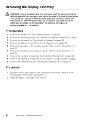
.... 2 Open the display to step 3 in "Removing the Hard Drive" on page 19. 7 Remove the wireless minicard. Procedure 1 Note the camera and antenna cable routing and remove the cables from step 1 to an angle of 90 degrees. 50 | Removing the Display Assembly Prerequisites 1 Remove the battery. See "Removing the Battery" on page 32. 8 Remove the cooling assembly. See "Removing the Wireless Card" on page 10. 2 Remove the memory modules. Removing the Display Assembly WARNING: Before working inside...
.... 2 Open the display to step 3 in "Removing the Hard Drive" on page 19. 7 Remove the wireless minicard. Procedure 1 Note the camera and antenna cable routing and remove the cables from step 1 to an angle of 90 degrees. 50 | Removing the Display Assembly Prerequisites 1 Remove the battery. See "Removing the Battery" on page 32. 8 Remove the cooling assembly. See "Removing the Wireless Card" on page 10. 2 Remove the memory modules. Removing the Display Assembly WARNING: Before working inside...
Service Manual
Page 57
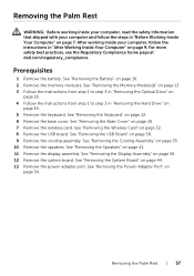
... "Removing the USB Board" on page 44. 13 Remove the power-adapter port. Removing the Palm Rest | 57 See "Removing the Memory Module(s)" on page 13 3 Follow the instructions from step 1 to step 3 in "Removing the Optical Drive" on page 16. 4 Follow the instructions from step 1 to step 3 in "Removing the Hard Drive" on page 50. 12 Remove the system board. See "Removing the Display Assembly" on page 19. 5 Remove the keyboard. See "Removing the Wireless Card...
... "Removing the USB Board" on page 44. 13 Remove the power-adapter port. Removing the Palm Rest | 57 See "Removing the Memory Module(s)" on page 13 3 Follow the instructions from step 1 to step 3 in "Removing the Optical Drive" on page 16. 4 Follow the instructions from step 1 to step 3 in "Removing the Hard Drive" on page 50. 12 Remove the system board. See "Removing the Display Assembly" on page 19. 5 Remove the keyboard. See "Removing the Wireless Card...
Service Manual
Page 61
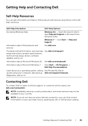
... services See dell.com. Getting Help and Contacting Dell | 61 Troubleshooting information, user manuals, See dell.com/support. setup instructions, product specifications, technical help on Dell products and services using your purchase invoice, packing slip, bill, or Dell product catalog. diagnostics, and so on Information about your operating system, setting See Me and My Dell at up and using these online selfhelp resources: Self-Help Information Self-Help Options Accessing Windows Help Windows...
... services See dell.com. Getting Help and Contacting Dell | 61 Troubleshooting information, user manuals, See dell.com/support. setup instructions, product specifications, technical help on Dell products and services using your purchase invoice, packing slip, bill, or Dell product catalog. diagnostics, and so on Information about your operating system, setting See Me and My Dell at up and using these online selfhelp resources: Self-Help Information Self-Help Options Accessing Windows Help Windows...


