Owners Manual
Page 3
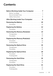
... Tools 7 Safety Instructions 8 After Working Inside Your Computer 9 Removing the Battery 10 Procedure 10 Replacing the Battery 12 Procedure 12 Removing the Memory Module(s 13 Prerequisites 13 Procedure 13 Replacing the Memory Module(s 15 Procedure 15 Postrequisites 15 Removing the Optical Drive 16 Prerequisites 16 Procedure 16 Replacing the Optical Drive 18 Procedure 18 Postrequisites 18 Removing the Hard Drive 19 Prerequisites 19 Procedure 19 Replacing the Hard Drive 21 Procedure 21...
... Tools 7 Safety Instructions 8 After Working Inside Your Computer 9 Removing the Battery 10 Procedure 10 Replacing the Battery 12 Procedure 12 Removing the Memory Module(s 13 Prerequisites 13 Procedure 13 Replacing the Memory Module(s 15 Procedure 15 Postrequisites 15 Removing the Optical Drive 16 Prerequisites 16 Procedure 16 Replacing the Optical Drive 18 Procedure 18 Postrequisites 18 Removing the Hard Drive 19 Prerequisites 19 Procedure 19 Replacing the Hard Drive 21 Procedure 21...
Owners Manual
Page 7
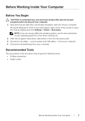
... before turning off your computer. Before Working Inside Your Computer Before You Begin CAUTION: To avoid data loss, save and close all open files, exit all open the Charms sidebar and click Settings→ Power→ Shut down , disconnect it from your computer. such as power and USB cables - Microsoft Windows 8: Point to the lower/upper-right corner of your operating...
... before turning off your computer. Before Working Inside Your Computer Before You Begin CAUTION: To avoid data loss, save and close all open files, exit all open the Charms sidebar and click Settings→ Power→ Shut down , disconnect it from your computer. such as power and USB cables - Microsoft Windows 8: Point to the lower/upper-right corner of your operating...

Owners Manual
Page 8
..., replace all power sources before connecting to the power source. After you work surface is authorized to remove the computer cover and access any connector pins. CAUTION: When you must disengage before disconnecting the cable. WARNING: Disconnect all covers, panels, and screws before opening the computer cover or panels. When disconnecting cables, keep them by touching an unpainted metal surface, such as the metal at dell.com...
..., replace all power sources before connecting to the power source. After you work surface is authorized to remove the computer cover and access any connector pins. CAUTION: When you must disengage before disconnecting the cable. WARNING: Disconnect all covers, panels, and screws before opening the computer cover or panels. When disconnecting cables, keep them by touching an unpainted metal surface, such as the metal at dell.com...
Owners Manual
Page 13
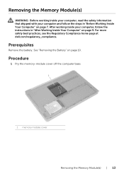
... best practices, see the Regulatory Compliance home page at dell.com/regulatory_compliance. After working inside your computer and follow the instructions in "Before Working Inside Your Computer" on page 7. See "Removing the Battery" on page 10. Procedure 1 Pry the memory-module cover off the computer base. 1 1 memory-module cover Removing the Memory Module(s) | 13 Removing the Memory Module(s) WARNING: Before working inside your computer, read the safety information that...
... best practices, see the Regulatory Compliance home page at dell.com/regulatory_compliance. After working inside your computer and follow the instructions in "Before Working Inside Your Computer" on page 7. See "Removing the Battery" on page 10. Procedure 1 Pry the memory-module cover off the computer base. 1 1 memory-module cover Removing the Memory Module(s) | 13 Removing the Memory Module(s) WARNING: Before working inside your computer, read the safety information that...

Owners Manual
Page 14
2 Carefully spread apart the securing clips on each end of the memory-module connector until the memory module pops up. 3 Remove the memory module from the computer. 1 2 3 1 memory-module connector 3 memory module 2 securing clips (2) 14 | Removing the Memory Module(s)
2 Carefully spread apart the securing clips on each end of the memory-module connector until the memory module pops up. 3 Remove the memory module from the computer. 1 2 3 1 memory-module connector 3 memory module 2 securing clips (2) 14 | Removing the Memory Module(s)

Owners Manual
Page 15
... memory module down until it . 3 Replace the memory-module cover. See "Replacing the Battery" on page 7. Replacing the Memory Module(s) WARNING: Before working inside your computer and follow the instructions in "Before Working Inside Your Computer" on page 12. 1 2 3 1 memory-module connector 3 memory module 2 securing clips (2) Replacing the Memory Module(s) | 15 NOTE: If you do not hear the click, remove the memory module and re-install it clicks into the connector at dell.com/regulatory_compliance. Replace the battery...
... memory module down until it . 3 Replace the memory-module cover. See "Replacing the Battery" on page 7. Replacing the Memory Module(s) WARNING: Before working inside your computer and follow the instructions in "Before Working Inside Your Computer" on page 12. 1 2 3 1 memory-module connector 3 memory module 2 securing clips (2) Replacing the Memory Module(s) | 15 NOTE: If you do not hear the click, remove the memory module and re-install it clicks into the connector at dell.com/regulatory_compliance. Replace the battery...

Owners Manual
Page 18
..." on page 7. Replacing the Optical Drive WARNING: Before working inside your computer, read the safety information that secures the optical drive to the optical-drive. 2 Align the screw hole on the optical-drive bracket with your computer, follow the steps in "After Working Inside Your Computer" on page 9. Procedure 1 Connect the optical-drive bezel to the computer base. 6 Replace the memory-module cover.
..." on page 7. Replacing the Optical Drive WARNING: Before working inside your computer, read the safety information that secures the optical drive to the optical-drive. 2 Align the screw hole on the optical-drive bracket with your computer, follow the steps in "After Working Inside Your Computer" on page 9. Procedure 1 Connect the optical-drive bezel to the computer base. 6 Replace the memory-module cover.

Owners Manual
Page 19
... instructions in "After Working Inside Your Computer" on page 10. Prerequisites Remove the battery. CAUTION: To avoid data loss, do not remove the hard drive while the computer is in Sleep or On state. Exercise care when handling the hard drive. See "Removing the Battery" on page 9. After working inside your computer, follow the steps in "Before Working Inside Your Computer" on page 7. Removing the Hard Drive...
... instructions in "After Working Inside Your Computer" on page 10. Prerequisites Remove the battery. CAUTION: To avoid data loss, do not remove the hard drive while the computer is in Sleep or On state. Exercise care when handling the hard drive. See "Removing the Battery" on page 9. After working inside your computer, follow the steps in "Before Working Inside Your Computer" on page 7. Removing the Hard Drive...
Owners Manual
Page 26
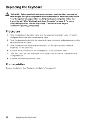
... cable. 3 Slide the tabs on the keyboard into the slots on the palm-rest and snap the keyboard on page 12. 26 | Replacing the Keyboard See "Replacing the Battery" on the palm rest. 4 Replace the screws that secure the keyboard to the computer base. 5 Turn the computer over and replace the screws that shipped with your computer, follow the steps in "After Working...
... cable. 3 Slide the tabs on the keyboard into the slots on the palm-rest and snap the keyboard on page 12. 26 | Replacing the Keyboard See "Replacing the Battery" on the palm rest. 4 Replace the screws that secure the keyboard to the computer base. 5 Turn the computer over and replace the screws that shipped with your computer, follow the steps in "After Working...
Owners Manual
Page 30
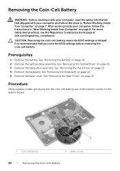
... battery resets the BIOS settings to default. Prerequisites 1 Remove the battery. After working inside your computer and follow the instructions in "Before Working Inside Your Computer" on page 9. See "Removing the Battery" on page 22. 5 Remove the base cover. See "Removing the Keyboard" on page 10. 2 Remove the optical-drive assembly. Procedure Using a plastic scribe, gently pry out the coin-cell battery out of the battery socket on page 16. 3 Remove the hard-drive...
... battery resets the BIOS settings to default. Prerequisites 1 Remove the battery. After working inside your computer and follow the instructions in "Before Working Inside Your Computer" on page 9. See "Removing the Battery" on page 22. 5 Remove the base cover. See "Removing the Keyboard" on page 10. 2 Remove the optical-drive assembly. Procedure Using a plastic scribe, gently pry out the coin-cell battery out of the battery socket on page 16. 3 Remove the hard-drive...
Owners Manual
Page 32
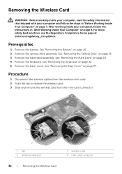
... cables (2) 32 | Removing the Wireless Card 4 3 2 wireless card 4 mini-card connector See "Removing the Battery" on page 16. 3 Remove the hard-drive assembly. See "Removing the Keyboard" on page 19 4 Remove the keyboard. Removing the Wireless Card WARNING: Before working inside your computer, read the safety information that shipped with your computer, follow the steps in "After Working Inside Your Computer" on page 27. After working inside your computer and follow the instructions...
... cables (2) 32 | Removing the Wireless Card 4 3 2 wireless card 4 mini-card connector See "Removing the Battery" on page 16. 3 Remove the hard-drive assembly. See "Removing the Keyboard" on page 19 4 Remove the keyboard. Removing the Wireless Card WARNING: Before working inside your computer, read the safety information that shipped with your computer, follow the steps in "After Working Inside Your Computer" on page 27. After working inside your computer and follow the instructions...
Owners Manual
Page 33
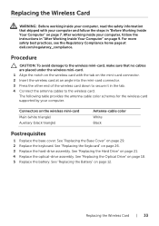
... 29. 2 Replace the keyboard. See "Replacing the Base Cover" on the wireless mini-card Main (white triangle) Auxiliary (black triangle) Antenna-cable color White Black Postrequisites 1 Replace the base cover. See "Replacing the Keyboard" on page 12. See "Replacing the Battery" on page 26. 3 Replace the hard-drive assembly. See "Replacing the Hard Drive" on page 18. 5 Replace the battery. See "Replacing the Optical Drive" on page 21. 4 Replace the optical-drive assembly. Replacing the Wireless Card WARNING: Before working inside...
... 29. 2 Replace the keyboard. See "Replacing the Base Cover" on the wireless mini-card Main (white triangle) Auxiliary (black triangle) Antenna-cable color White Black Postrequisites 1 Replace the base cover. See "Replacing the Keyboard" on page 12. See "Replacing the Battery" on page 26. 3 Replace the hard-drive assembly. See "Replacing the Hard Drive" on page 18. 5 Replace the battery. See "Replacing the Optical Drive" on page 21. 4 Replace the optical-drive assembly. Replacing the Wireless Card WARNING: Before working inside...
Owners Manual
Page 41
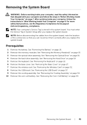
... Setup after you replace the system board. See "Removing the Memory Module(s)" on page 16. 4 Remove the hard-drive assembly. See "Removing the Optical Drive" on page 13. 3 Remove the optical-drive assembly. Removing the System Board WARNING: Before working inside your computer and follow the instructions in the system board. See "Removing the Hard Drive" on page 32. 8 Remove the USB board. See "Removing the Wireless Card" on page 19. 5 Remove the keyboard. See "Removing the Battery" on page 27. 7 Remove...
... Setup after you replace the system board. See "Removing the Memory Module(s)" on page 16. 4 Remove the hard-drive assembly. See "Removing the Optical Drive" on page 13. 3 Remove the optical-drive assembly. Removing the System Board WARNING: Before working inside your computer and follow the instructions in the system board. See "Removing the Hard Drive" on page 32. 8 Remove the USB board. See "Removing the Wireless Card" on page 19. 5 Remove the keyboard. See "Removing the Battery" on page 27. 7 Remove...
Owners Manual
Page 45
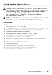
... camera cable to the system board. 5 Connect the power-adapter port cable to the system board. 6 Connect the hard-drive cable to the hard-disc connector. 7 Connect the speaker cable to the system board. 8 Slide the USB-board cable to the computer base. After working inside your computer and follow the instructions in "Before Working Inside Your Computer" on page 7. For more safety best practices, see the Regulatory Compliance home page at dell.com/regulatory_compliance. Replacing...
... camera cable to the system board. 5 Connect the power-adapter port cable to the system board. 6 Connect the hard-drive cable to the hard-disc connector. 7 Connect the speaker cable to the system board. 8 Slide the USB-board cable to the computer base. After working inside your computer and follow the instructions in "Before Working Inside Your Computer" on page 7. For more safety best practices, see the Regulatory Compliance home page at dell.com/regulatory_compliance. Replacing...

Owners Manual
Page 47
... Hard Drive" on page 10. 2 Remove the memory modules. See "Removing the Wireless Card" on page 34. 10 Remove the coin cell battery. See "Removing the Cooling Assembly" on page 32. 8 Remove the USB board. See "Removing the System Board" on page 22. 6 Remove the base cover. See "Removing the Keyboard" on page 41. 13 Remove the power-adapter port. See "Removing the Speakers" on page 57. Removing the Palm Rest | 47 Prerequisites 1 Remove the battery. See "Removing the Power-Adapter Port...
... Hard Drive" on page 10. 2 Remove the memory modules. See "Removing the Wireless Card" on page 34. 10 Remove the coin cell battery. See "Removing the Cooling Assembly" on page 32. 8 Remove the USB board. See "Removing the System Board" on page 22. 6 Remove the base cover. See "Removing the Keyboard" on page 41. 13 Remove the power-adapter port. See "Removing the Speakers" on page 57. Removing the Palm Rest | 47 Prerequisites 1 Remove the battery. See "Removing the Power-Adapter Port...

Owners Manual
Page 51
... Keyboard" on page 29. 9 Replace the keyboard. See "Replacing the Base Cover" on page 26. 10 Replace the hard-drive assembly. See "Replacing the Hard Drive" on page 18. 12 Replace the memory modules. See "Replacing the Optical Drive" on page 21. 11 Replace the optical-drive assembly. Postrequisites 1 Replace the power-adapter port. See "Replacing the Power-Adapter Port" on page 40 4 Replace the coin cell battery. See "Replacing the Speakers" on page 59. 2 Replace the system board. See "Replacing the Wireless Card...
... Keyboard" on page 29. 9 Replace the keyboard. See "Replacing the Base Cover" on page 26. 10 Replace the hard-drive assembly. See "Replacing the Hard Drive" on page 18. 12 Replace the memory modules. See "Replacing the Optical Drive" on page 21. 11 Replace the optical-drive assembly. Postrequisites 1 Replace the power-adapter port. See "Replacing the Power-Adapter Port" on page 40 4 Replace the coin cell battery. See "Replacing the Speakers" on page 59. 2 Replace the system board. See "Replacing the Wireless Card...
Owners Manual
Page 52
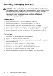
... base cover. See "Removing the Hard Drive" on page 10. 2 Remove the keyboard. Procedure 1 Disconnect the display cable from the system board. 2 Peel off the tape from the USB-board cable. 3 Lift the connector latch and, using the pull-tab, disconnect the USB-board cable from the system board. 4 Disconnect the speaker cable from the system board. 5 Disconnect the hard-drive cable from the system board. 6 Disconnect the power-adapter port cable from the system board. 7 Disconnect the camera cable...
... base cover. See "Removing the Hard Drive" on page 10. 2 Remove the keyboard. Procedure 1 Disconnect the display cable from the system board. 2 Peel off the tape from the USB-board cable. 3 Lift the connector latch and, using the pull-tab, disconnect the USB-board cable from the system board. 4 Disconnect the speaker cable from the system board. 5 Disconnect the hard-drive cable from the system board. 6 Disconnect the power-adapter port cable from the system board. 7 Disconnect the camera cable...

Owners Manual
Page 56
... board. 8 Connect the power-adapter port cable to the system board. 9 Connect the hard-drive cable to the system board. 10 Connect the speaker cable to the system board. 11 Slide the USB-board cable to the connector latch and connect it to the system board by snapping it in place. 12 Adhere the tape to the USB-board cable. 13 Connect the display cable to the system board. See "Replacing the Hard Drive" on page 29. 3 Replace the keyboard. Postrequisites 1 Replace the wireless...
... board. 8 Connect the power-adapter port cable to the system board. 9 Connect the hard-drive cable to the system board. 10 Connect the speaker cable to the system board. 11 Slide the USB-board cable to the connector latch and connect it to the system board by snapping it in place. 12 Adhere the tape to the USB-board cable. 13 Connect the display cable to the system board. See "Replacing the Hard Drive" on page 29. 3 Replace the keyboard. Postrequisites 1 Replace the wireless...
Owners Manual
Page 57
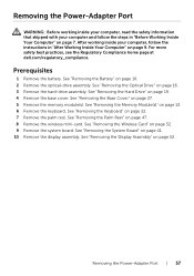
... the instructions in "Before Working Inside Your Computer" on page 16. 3 Remove the hard-drive assembly. See "Removing the Hard Drive" on page 9. See "Removing the Base Cover" on page 52. See "Removing the Display Assembly" on page 27. 5 Remove the memory module(s). See "Removing the Palm Rest" on page 13. 6 Remove the keyboard. See "Removing the Memory Module(s)" on page 47. 8 Remove the wireless mini-card. See "Removing the Wireless Card" on page 10. 2 Remove the optical-drive...
... the instructions in "Before Working Inside Your Computer" on page 16. 3 Remove the hard-drive assembly. See "Removing the Hard Drive" on page 9. See "Removing the Base Cover" on page 52. See "Removing the Display Assembly" on page 27. 5 Remove the memory module(s). See "Removing the Palm Rest" on page 13. 6 Remove the keyboard. See "Removing the Memory Module(s)" on page 47. 8 Remove the wireless mini-card. See "Removing the Wireless Card" on page 10. 2 Remove the optical-drive...

Specifications
Page 3
Ports and Connectors External: Network USB HDMI port Audio Internal: Mini-card One RJ45 port • Three USB 3.0 ports • One USB 3.0 port with PowerShare One HDMI port One headset port One half mini-card slot for Wi-Fi and Bluetooth combo Communications Network adapter Wireless RJ45 port • Wi-Fi 802.11 b/g/n • Bluetooth 4.0 • Wireless Display (optional) Video Controller: Integrated Discrete Memory: Integrated Memory Discrete Memory Intel HD Graphics 4400 nVidia GeForce GT 750M Shared system memory 2 GB GDDR5 Audio Controller Speaker Internal microphone Volume ...
Ports and Connectors External: Network USB HDMI port Audio Internal: Mini-card One RJ45 port • Three USB 3.0 ports • One USB 3.0 port with PowerShare One HDMI port One headset port One half mini-card slot for Wi-Fi and Bluetooth combo Communications Network adapter Wireless RJ45 port • Wi-Fi 802.11 b/g/n • Bluetooth 4.0 • Wireless Display (optional) Video Controller: Integrated Discrete Memory: Integrated Memory Discrete Memory Intel HD Graphics 4400 nVidia GeForce GT 750M Shared system memory 2 GB GDDR5 Audio Controller Speaker Internal microphone Volume ...


