
Owners Manual
Page 3
Contents 1 Before You Begin 7 Turn Off Your Computer and Connected Devices . . . 7 Safety Instructions 7 Recommended Tools 8 2 After Working Inside Your Computer 9 3 Switch 11 Removing the Switch 11 Replacing the Switch 12 4 ...
Contents 1 Before You Begin 7 Turn Off Your Computer and Connected Devices . . . 7 Safety Instructions 7 Recommended Tools 8 2 After Working Inside Your Computer 9 3 Switch 11 Removing the Switch 11 Replacing the Switch 12 4 ...

Owners Manual
Page 7
...CAUTION: To avoid damaging the components and cards, handle them by touching an unpainted metal surface, such as the metal at dell.com/ regulatory_compliance. 1 Before You Begin Turn Off Your Computer and Connected Devices CAUTION: To avoid losing data, save and close all open files and exit all open...your computer. 1 Save and close all open files and exit all open programs. 2 Click Start and click Shut down and then the computer turns off. While you work surface is unplugged, to protect your computer from your computer. 5 Press and hold the power button for complete information...
...CAUTION: To avoid damaging the components and cards, handle them by touching an unpainted metal surface, such as the metal at dell.com/ regulatory_compliance. 1 Before You Begin Turn Off Your Computer and Connected Devices CAUTION: To avoid losing data, save and close all open files and exit all open...your computer. 1 Save and close all open files and exit all open programs. 2 Click Start and click Shut down and then the computer turns off. While you work surface is unplugged, to protect your computer from your computer. 5 Press and hold the power button for complete information...

Owners Manual
Page 9
2 After Working Inside Your Computer After you removed before working on your computer • Connect your computer. Failure to their electrical outlets CAUTION: Before turning on your computer, replace all screws and ensure that no stray screws remain inside your computer • Connect any external devices, cables, cards, and any ...
2 After Working Inside Your Computer After you removed before working on your computer • Connect your computer. Failure to their electrical outlets CAUTION: Before turning on your computer, replace all screws and ensure that no stray screws remain inside your computer • Connect any external devices, cables, cards, and any ...

Owners Manual
Page 13
... additional safety best practices information, see the Regulatory Compliance Homepage at dell.com/regulatory_compliance. 4 Battery WARNING: Before working inside your computer and follow the steps in "After Working Inside Your Computer" on page 7. Removing the Battery 1 Close the display and turn the computer over. 2 Slide the battery release latches to the unlock...
... additional safety best practices information, see the Regulatory Compliance Homepage at dell.com/regulatory_compliance. 4 Battery WARNING: Before working inside your computer and follow the steps in "After Working Inside Your Computer" on page 7. Removing the Battery 1 Close the display and turn the computer over. 2 Slide the battery release latches to the unlock...

Owners Manual
Page 15
... extremely careful when removing and handling the keyboard. For additional safety best practices information, see the Regulatory Compliance Homepage at dell.com/regulatory_compliance. Failure to replace. 5 Keyboard WARNING: Before working inside your computer, read the safety information that shipped... scribe 4 palm rest Keyboard | 15 Removing the Keyboard Prerequisites 1 Remove the battery. Be careful when removing and handling the keyboard. 1 Turn the computer over and open the display as far as possible. 2 Using a plastic scribe, release the keyboard from the tabs on page 13.
... extremely careful when removing and handling the keyboard. For additional safety best practices information, see the Regulatory Compliance Homepage at dell.com/regulatory_compliance. Failure to replace. 5 Keyboard WARNING: Before working inside your computer, read the safety information that shipped... scribe 4 palm rest Keyboard | 15 Removing the Keyboard Prerequisites 1 Remove the battery. Be careful when removing and handling the keyboard. 1 Turn the computer over and open the display as far as possible. 2 Using a plastic scribe, release the keyboard from the tabs on page 13.
Owners Manual
Page 16
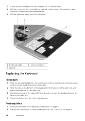
Postrequisites 1 Replace the battery. 3 Carefully turn the keyboard over and place it on the palm rest. 4 Lift the connector latch and pull the pull-tab to disconnect the keyboard cable from ... | Keyboard See "Replacing the Battery" on page 13. 2 Follow the instructions in "After Working Inside Your Computer" on the palm rest. 4 Close the display and turn the computer over.
Postrequisites 1 Replace the battery. 3 Carefully turn the keyboard over and place it on the palm rest. 4 Lift the connector latch and pull the pull-tab to disconnect the keyboard cable from ... | Keyboard See "Replacing the Battery" on page 13. 2 Follow the instructions in "After Working Inside Your Computer" on the palm rest. 4 Close the display and turn the computer over.

Owners Manual
Page 20
... | Memory Module(s) See "Replacing the Base Cover" on the computer. To confirm the amount of memory installed in "After Working Inside Your Computer" on page 9. 4 Turn on page 18. 2 Replace the battery. Replacing the Memory Module(s) Procedure 1 Align the notch on the memory module with the tab on the memory-module...
... | Memory Module(s) See "Replacing the Base Cover" on the computer. To confirm the amount of memory installed in "After Working Inside Your Computer" on page 9. 4 Turn on page 18. 2 Replace the battery. Replacing the Memory Module(s) Procedure 1 Align the notch on the memory module with the tab on the memory-module...

Owners Manual
Page 28
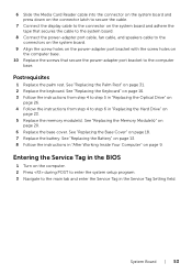
2 Turn the computer over. 3 Lift the connector latches and pull the pull-tabs to disconnect the power-button board cable, touchpad cable, and hot-key board cable from the connectors on the system board. 12 34 5 1 power-button board cable 3 connector latch 5 hot-key board cable 2 pull-tab 4 touchpad cable 28 | Palm Rest
2 Turn the computer over. 3 Lift the connector latches and pull the pull-tabs to disconnect the power-button board cable, touchpad cable, and hot-key board cable from the connectors on the system board. 12 34 5 1 power-button board cable 3 connector latch 5 hot-key board cable 2 pull-tab 4 touchpad cable 28 | Palm Rest
Owners Manual
Page 31
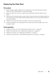
... See "Replacing the Base Cover" on the connector latches to secure the cables. 4 Replace the screws that secure the palm rest to the computer base. 5 Turn the computer over and replace the screws that secure the palm rest to the computer base. Replacing the Palm Rest Procedure 1 Slide the status-lights...
... See "Replacing the Base Cover" on the connector latches to secure the cables. 4 Replace the screws that secure the palm rest to the computer base. 5 Turn the computer over and replace the screws that secure the palm rest to the computer base. Replacing the Palm Rest Procedure 1 Slide the status-lights...

Owners Manual
Page 41
Procedure 1 Remove the screws that secure the display panel to the display cover. 2 Carefully lift the display panel and turn it over. 1 1 display cover 3 screws (8) 2 3 2 display panel Display Assembly | 41
Procedure 1 Remove the screws that secure the display panel to the display cover. 2 Carefully lift the display panel and turn it over. 1 1 display cover 3 screws (8) 2 3 2 display panel Display Assembly | 41

Owners Manual
Page 43
Display Assembly | 43 5 Turn the display panel over and place it on a clean surface. 6 Remove the screws that secure the display-panel brackets to the display panel. 7 Remove the ... display-panel bracket with the screw holes on the display panel and replace the screws that secure the display-panel bracket to the display panel. 2 Turn the display panel over. 3 Adhere the display cable to the back of the display panel. 4 Connect the display cable to the display-board connector and...
Display Assembly | 43 5 Turn the display panel over and place it on a clean surface. 6 Remove the screws that secure the display-panel brackets to the display panel. 7 Remove the ... display-panel bracket with the screw holes on the display panel and replace the screws that secure the display-panel bracket to the display panel. 2 Turn the display panel over. 3 Adhere the display cable to the back of the display panel. 4 Connect the display cable to the display-board connector and...

Owners Manual
Page 46
Procedure 1 Remove the screws that secure the display panel to the display cover. 2 Carefully lift the display panel and turn it over. 1 2 3 1 display cover 3 screws (8) 2 display panel 46 | Camera Module
Procedure 1 Remove the screws that secure the display panel to the display cover. 2 Carefully lift the display panel and turn it over. 1 2 3 1 display cover 3 screws (8) 2 display panel 46 | Camera Module

Owners Manual
Page 48
... display cover. 2 Connect the camera cable to the connector on the camera module. 3 Replace the screw that secures the camera module to the display cover. 4 Turn the display panel over and place it on the display cover. 5 Align the screw holes on the display panel with the screw holes on the...
... display cover. 2 Connect the camera cable to the connector on the camera module. 3 Replace the screw that secures the camera module to the display cover. 4 Turn the display panel over and place it on the display cover. 5 Align the screw holes on the display panel with the screw holes on the...
Owners Manual
Page 53
... page 13. 8 Follow the instructions in "After Working Inside Your Computer" on page 20. 6 Replace the base cover. Entering the Service Tag in the BIOS 1 Turn on the computer. 2 Press during POST to enter the system setup program. 3 Navigate to step 6 in "Replacing the Hard Drive" on page 23. 5 Replace the...
... page 13. 8 Follow the instructions in "After Working Inside Your Computer" on page 20. 6 Replace the base cover. Entering the Service Tag in the BIOS 1 Turn on the computer. 2 Press during POST to enter the system setup program. 3 Navigate to step 6 in "Replacing the Hard Drive" on page 23. 5 Replace the...

Owners Manual
Page 61
... Hard Drive" on page 9. Processor | 61 CAUTION: To avoid damage to the processor, hold the screwdriver perpendicular to the processor when turning the cam screw. 2 Tighten the ZIF socket by turning the cam screw clockwise to secure the processor module to the system board. Postrequisites 1 Replace the thermal-cooling assembly. See "Replacing...
... Hard Drive" on page 9. Processor | 61 CAUTION: To avoid damage to the processor, hold the screwdriver perpendicular to the processor when turning the cam screw. 2 Tighten the ZIF socket by turning the cam screw clockwise to secure the processor module to the system board. Postrequisites 1 Replace the thermal-cooling assembly. See "Replacing...

Owners Manual
Page 83
...the folder where you do not have your computer's Service Tag or Express Service Code: a Enter your computer. b Click Submit and proceed to support.dell.com/support/downloads. 3 Locate the BIOS update file for your computer: NOTE: The Service Tag for me • Choose from My Products and ...update file icon and follow the instructions on the screen. If you downloaded the BIOS update file. Flashing the BIOS | 83 To flash the BIOS: 1 Turn on the computer. 2 Go to step 4. If you have your computer's Service Tag or Express Service Code: a Select one of the following options: ...
...the folder where you do not have your computer's Service Tag or Express Service Code: a Enter your computer. b Click Submit and proceed to support.dell.com/support/downloads. 3 Locate the BIOS update file for your computer: NOTE: The Service Tag for me • Choose from My Products and ...update file icon and follow the instructions on the screen. If you downloaded the BIOS update file. Flashing the BIOS | 83 To flash the BIOS: 1 Turn on the computer. 2 Go to step 4. If you have your computer's Service Tag or Express Service Code: a Select one of the following options: ...
Me and My Dell
Page 3
Contents Charms Sidebar 15 Signing in to Windows 8 16 Closing a Windows 8 app 17 Turning off your computer - Windows 8 17 Power Adapter 21 Battery 22 Laptop Battery 22 Conserving the Battery Power 22 Coin-Cell Battery 23 Improving the Battery Performance 23 Touchpad 24 About Touchpad 24 Touchpad Gestures 24 Scroll 24 Zoom 26 Rotate 27 Flick 28 My Favorites 28 Desktop 28 Display 29 3D Display 29 Wireless Display 29 Touchscreen Display 30 Contents 3
Contents Charms Sidebar 15 Signing in to Windows 8 16 Closing a Windows 8 app 17 Turning off your computer - Windows 8 17 Power Adapter 21 Battery 22 Laptop Battery 22 Conserving the Battery Power 22 Coin-Cell Battery 23 Improving the Battery Performance 23 Touchpad 24 About Touchpad 24 Touchpad Gestures 24 Scroll 24 Zoom 26 Rotate 27 Flick 28 My Favorites 28 Desktop 28 Display 29 3D Display 29 Wireless Display 29 Touchscreen Display 30 Contents 3

Me and My Dell
Page 17
Windows 8 To turn off your computer - NOTE: You can also choose to put your computer: 1. Closing a Windows 8 app 17 Swipe from the top of the screen to ... the right edge of the screen (or if you are using touchscreen, drag the app to the bottom of the screen), and then click Settings. 2. Turning off your computer in sleep or hibernate state.
Windows 8 To turn off your computer - NOTE: You can also choose to put your computer: 1. Closing a Windows 8 app 17 Swipe from the top of the screen to ... the right edge of the screen (or if you are using touchscreen, drag the app to the bottom of the screen), and then click Settings. 2. Turning off your computer in sleep or hibernate state.
Me and My Dell
Page 23
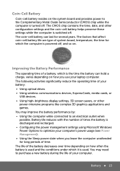
...-Cell Battery Coin-cell battery resides on the system board and provides power to the Complementary Metal Oxide Semiconductor (CMOS) chip while the computer is turned off .
...-Cell Battery Coin-cell battery resides on the system board and provides power to the Complementary Metal Oxide Semiconductor (CMOS) chip while the computer is turned off .
Me and My Dell
Page 34
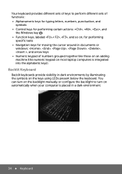
... sets of numbers grouped together like those on an adding machine (the numeric keypad on the keys using LEDs present below the keyboard. You can turn on automatically when your computer is integrated into the alphabetic keys). Backlit Keyboard Backlit keyboards provide visibility in dark environments by illuminating the symbols on...
... sets of numbers grouped together like those on an adding machine (the numeric keypad on the keys using LEDs present below the keyboard. You can turn on automatically when your computer is integrated into the alphabetic keys). Backlit Keyboard Backlit keyboards provide visibility in dark environments by illuminating the symbols on...


