
Owner's Manual
Page 5
... Local Area Network 45 Determining Your Network Type 45 Connecting to a Wireless Network in Microsoft® Windows® XP. . . . . 45 7 Solving Problems Dell Diagnostics 49 When to Use the Dell Diagnostics 49 Error Messages 51 Video and Display Problems 52 If the display is blank 52 If the display is difficult to...
... Local Area Network 45 Determining Your Network Type 45 Connecting to a Wireless Network in Microsoft® Windows® XP. . . . . 45 7 Solving Problems Dell Diagnostics 49 When to Use the Dell Diagnostics 49 Error Messages 51 Video and Display Problems 52 If the display is blank 52 If the display is difficult to...

Owner's Manual
Page 6
... 60 Resolving Software and Hardware Incompatibilities 60 Restoring Your Operating System 61 Using Microsoft Windows XP System Restore 61 Using Dell PC Restore by Symantec 62 8 Adding and Replacing Parts Before You Begin 65 Recommended Tools 65 Shutting Down Your Computer 65 Hard Drive 66 Returning a Hard Drive to... Dell 68 Memory 68 Modem and Mini PCI Card 71 Replacing the Modem 72 Adding a Mini PCI Card 72 CD or ...
... 60 Resolving Software and Hardware Incompatibilities 60 Restoring Your Operating System 61 Using Microsoft Windows XP System Restore 61 Using Dell PC Restore by Symantec 62 8 Adding and Replacing Parts Before You Begin 65 Recommended Tools 65 Shutting Down Your Computer 65 Hard Drive 66 Returning a Hard Drive to... Dell 68 Memory 68 Modem and Mini PCI Card 71 Replacing the Modem 72 Adding a Mini PCI Card 72 CD or ...
Owner's Manual
Page 50
... any key to run . You can customize the tests you contact Dell, technical support will ask for your part. NOTE: The Service Tag for your Service Tag. 50 Solving Problems If you want to start the Dell Diagnostics from the diagnostics utility partition on your system board, keyboard, ...• If a failure is detected, the computer stops and beeps. If the Pre-boot System Assessment completes successfully, you want to the Dell Diagnostics. This test typically takes 10 to 20 minutes and requires no interaction on the symptom of the problem you are detected during a test...
... any key to run . You can customize the tests you contact Dell, technical support will ask for your part. NOTE: The Service Tag for your Service Tag. 50 Solving Problems If you want to start the Dell Diagnostics from the diagnostics utility partition on your system board, keyboard, ...• If a failure is detected, the computer stops and beeps. If the Pre-boot System Assessment completes successfully, you want to the Dell Diagnostics. This test typically takes 10 to 20 minutes and requires no interaction on the symptom of the problem you are detected during a test...

Owner's Manual
Page 54
... and Screen resolution. www.dell.com | support.dell.com ADJUST THE WINDOWS DISPLAY SETTINGS - 1 Click the Start button and click Control Panel. 2 Click Appearance and Themes. 3 Click the area you want to change or click the Display icon. 4 Try different settings for instructions. 54 Solving Problems R E I N S T A L L T H E S C A N N E R D R I V E R - S E E " E R R O R M E S S A G E S " - If only part of the display is...
... and Screen resolution. www.dell.com | support.dell.com ADJUST THE WINDOWS DISPLAY SETTINGS - 1 Click the Start button and click Control Panel. 2 Click Appearance and Themes. 3 Click the area you want to change or click the Display icon. 4 Try different settings for instructions. 54 Solving Problems R E I N S T A L L T H E S C A N N E R D R I V E R - S E E " E R R O R M E S S A G E S " - If only part of the display is...

Owner's Manual
Page 65
Adding and Replacing Parts Before You Begin This section provides procedures for removing and installing the components in your own personal safety. NOTICE: When you pull connectors apart, keep ... following conditions exist: • You have performed the steps in your Product Information Guide. CAUTION: Handle components and cards with locking tabs; Adding and Replacing Parts 65 if you connect a cable, ensure that the following safety guidelines to help protect your computer from potential damage and to servicing that is not...
Adding and Replacing Parts Before You Begin This section provides procedures for removing and installing the components in your own personal safety. NOTICE: When you pull connectors apart, keep ... following conditions exist: • You have performed the steps in your Product Information Guide. CAUTION: Handle components and cards with locking tabs; Adding and Replacing Parts 65 if you connect a cable, ensure that the following safety guidelines to help protect your computer from potential damage and to servicing that is not...

Owner's Manual
Page 66
...remove the main battery before you service the computer. 9 Slide and hold the power button for hard drives from sources other than Dell. 66 Adding and Replacing Parts NOTICE: Hard drives are turned off when you shut down the computer. 3 Ensure that the computer and any attached devices are...the cable into the computer. 7 Remove any installed PC Cards from the PC Card slot. 8 Close the display and turn off . www.dell.com | support.dell.com NOTICE: To avoid damaging the computer, perform the following steps before you begin working inside the computer. 1 Ensure that the work surface. ...
...remove the main battery before you service the computer. 9 Slide and hold the power button for hard drives from sources other than Dell. 66 Adding and Replacing Parts NOTICE: Hard drives are turned off when you shut down the computer. 3 Ensure that the computer and any attached devices are...the cable into the computer. 7 Remove any installed PC Cards from the PC Card slot. 8 Close the display and turn off . www.dell.com | support.dell.com NOTICE: To avoid damaging the computer, perform the following steps before you begin working inside the computer. 1 Ensure that the work surface. ...

Owner's Manual
Page 67
... the drive into the bay, and push the hard drive until it is not in the computer, store it in your computer. Adding and Replacing Parts 67 If you use excessive force, you may damage the connector. 5 Insert the drive into place. To replace the hard drive in the hard drive...
... the drive into the bay, and push the hard drive until it is not in the computer, store it in your computer. Adding and Replacing Parts 67 If you use excessive force, you may damage the connector. 5 Insert the drive into place. To replace the hard drive in the hard drive...
Owner's Manual
Page 68
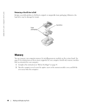
See page 80 for your old hard drive to Dell Return your computer. 1 Complete the instructions in "Before You Begin" on the system board. foam packaging hard drive Memory You can increase your computer. Otherwise, .... 2 Turn the computer over, loosen the captive screw in the memory module cover, and lift the cover away from the computer. 68 Adding and Replacing Parts www.dell.com | support.dell.com Returning a Hard Drive to Dell in its original or comparable foam packaging.
See page 80 for your old hard drive to Dell Return your computer. 1 Complete the instructions in "Before You Begin" on the system board. foam packaging hard drive Memory You can increase your computer. Otherwise, .... 2 Turn the computer over, loosen the captive screw in the memory module cover, and lift the cover away from the computer. 68 Adding and Replacing Parts www.dell.com | support.dell.com Returning a Hard Drive to Dell in its original or comparable foam packaging.

Owner's Manual
Page 69
captive screw memory module cover NOTE: Memory modules purchased from the connector. b Remove the module from Dell are covered under your computer warranty. 3 If you are replacing a memory module, remove the existing module: a Use your fingertips to carefully spread apart the securing clips on each end of the memory module connector until the module pops up. memory module securing clips Adding and Replacing Parts 69
captive screw memory module cover NOTE: Memory modules purchased from the connector. b Remove the module from Dell are covered under your computer warranty. 3 If you are replacing a memory module, remove the existing module: a Use your fingertips to carefully spread apart the securing clips on each end of the memory module connector until the module pops up. memory module securing clips Adding and Replacing Parts 69

Owner's Manual
Page 70
...the tab in the computer, click the Start button, click Help and Support, and then click Computer Information. 70 Adding and Replacing Parts If you do not feel the click, remove the module and reinstall it detects the additional memory and automatically updates the system configuration ...information. www.dell.com | support.dell.com 4 Ground yourself and install the new memory module: NOTE: If the memory module is difficult to close may not boot ...
...the tab in the computer, click the Start button, click Help and Support, and then click Computer Information. 70 Adding and Replacing Parts If you do not feel the click, remove the module and reinstall it detects the additional memory and automatically updates the system configuration ...information. www.dell.com | support.dell.com 4 Ground yourself and install the new memory module: NOTE: If the memory module is difficult to close may not boot ...

Owner's Manual
Page 71
Modem and Mini PCI Card 1 Complete the instructions in "Before You Begin" on page 65. 2 Turn the computer over, loosen the captive screw on the modem/Mini PCI card cover, and lift the cover away from the computer. Adding and Replacing Parts 71 captive screw modem/Mini PCI card cover 3 Continue to the appropriate section: • To add a modem, see the following section, "Adding a Modem." • To add a Mini PCI card, see page 72.
Modem and Mini PCI Card 1 Complete the instructions in "Before You Begin" on page 65. 2 Turn the computer over, loosen the captive screw on the modem/Mini PCI card cover, and lift the cover away from the computer. Adding and Replacing Parts 71 captive screw modem/Mini PCI card cover 3 Continue to the appropriate section: • To add a modem, see the following section, "Adding a Modem." • To add a Mini PCI card, see page 72.

Owner's Manual
Page 72
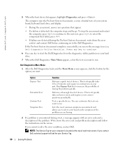
...802.11a/b, 802.11a/b/g) Wireless LAN Mini PCI cards. Approved Mini PCI Cards may be removed and installed by the user. 72 Adding and Replacing Parts do not force the connections. 3 Align the modem with the screw holes, and press the modem into the connector on the system board. 4 ... secure the modem to lift the modem out of its connector on the attached pull-tab to the system board. 5 Replace the cover. www.dell.com | support.dell.com Replacing the Modem 1 Remove the existing modem: a Remove the screws securing the modem to the modem. screws (2) modem cable connector modem...
...802.11a/b, 802.11a/b/g) Wireless LAN Mini PCI cards. Approved Mini PCI Cards may be removed and installed by the user. 72 Adding and Replacing Parts do not force the connections. 3 Align the modem with the screw holes, and press the modem into the connector on the system board. 4 ... secure the modem to lift the modem out of its connector on the attached pull-tab to the system board. 5 Replace the cover. www.dell.com | support.dell.com Replacing the Modem 1 Remove the existing modem: a Remove the screws securing the modem to the modem. screws (2) modem cable connector modem...

Owner's Manual
Page 73
... PCI card is not already installed, go to ensure correct insertion. If you feel resistance, check the connectors and realign the card. Adding and Replacing Parts 73 c Lift the Mini PCI card out of or under the card. NOTICE: The connectors are replacing a Mini PCI card, remove the existing card: a Disconnect...
... PCI card is not already installed, go to ensure correct insertion. If you feel resistance, check the connectors and realign the card. Adding and Replacing Parts 73 c Lift the Mini PCI card out of or under the card. NOTICE: The connectors are replacing a Mini PCI card, remove the existing card: a Disconnect...

Owner's Manual
Page 74
Mini PCI card antenna cables (2) Mini PCI card connector 3 Connect the antenna cables to the Mini PCI card. 4 Replace the cover. 74 Adding and Replacing Parts www.dell.com | support.dell.com 2 Align the Mini PCI card with the connector at a 45-degree angle, and press the Mini PCI card into the connector until it clicks.
Mini PCI card antenna cables (2) Mini PCI card connector 3 Connect the antenna cables to the Mini PCI card. 4 Replace the cover. 74 Adding and Replacing Parts www.dell.com | support.dell.com 2 Align the Mini PCI card with the connector at a 45-degree angle, and press the Mini PCI card into the connector until it clicks.

Owner's Manual
Page 75
captive screw memory module cover 3 Remove the screw labeled "O" next to the memory module cover. CD or DVD drive screw lever Adding and Replacing Parts 75 CD or DVD Drive 1 Complete the instructions in "Before You Begin" on page 65. 2 Turn the computer over, loosen the captive screw in the memory module cover, and lift the cover away from the computer.
captive screw memory module cover 3 Remove the screw labeled "O" next to the memory module cover. CD or DVD drive screw lever Adding and Replacing Parts 75 CD or DVD Drive 1 Complete the instructions in "Before You Begin" on page 65. 2 Turn the computer over, loosen the captive screw in the memory module cover, and lift the cover away from the computer.
Owner's Manual
Page 76
... drive. 5 Pull the drive out of the bay. 6 Slide the new drive into the bay until the drive is exposed. 76 Adding and Replacing Parts www.dell.com | support.dell.com 4 Press the lever next to the memory module connectors in the direction of the arrow on page 65. 2 Use a small flat-blade...
... drive. 5 Pull the drive out of the bay. 6 Slide the new drive into the bay until the drive is exposed. 76 Adding and Replacing Parts www.dell.com | support.dell.com 4 Press the lever next to the memory module connectors in the direction of the arrow on page 65. 2 Use a small flat-blade...

Owner's Manual
Page 77
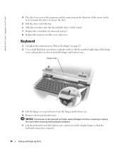
Adding and Replacing Parts 77 keyboard screws (4) keyboard keyboard connector interface connector 7 Remove the keyboard from the interface connector on the system board, and do not reverse the keyboard connector. 6 Pull up on the keyboard connector to the connector pins, press the keyboard connector evenly into the interface connector on the system board. NOTICE: To avoid damage to disconnect it from the bottom case.
Adding and Replacing Parts 77 keyboard screws (4) keyboard keyboard connector interface connector 7 Remove the keyboard from the interface connector on the system board, and do not reverse the keyboard connector. 6 Pull up on the keyboard connector to the connector pins, press the keyboard connector evenly into the interface connector on the system board. NOTICE: To avoid damage to disconnect it from the bottom case.

Owner's Manual
Page 78
keyboard screws (4) keyboard keyboard connector interface connector securing tabs (4) 9 Insert the four securing tabs on the system board. Ensure that all four securing tabs are engaged before trying to the interface connector on the keyboard into their respective slots in the palm rest, and lower the keyboard into the bottom case. www.dell.com | support.dell.com 8 Connect the keyboard connector of the replacement keyboard to completely seat the keyboard. 10 Replace the four keyboard screws. 11 Replace the hinge cover. 78 Adding and Replacing Parts
keyboard screws (4) keyboard keyboard connector interface connector securing tabs (4) 9 Insert the four securing tabs on the system board. Ensure that all four securing tabs are engaged before trying to the interface connector on the keyboard into their respective slots in the palm rest, and lower the keyboard into the bottom case. www.dell.com | support.dell.com 8 Connect the keyboard connector of the replacement keyboard to completely seat the keyboard. 10 Replace the four keyboard screws. 11 Replace the hinge cover. 78 Adding and Replacing Parts
Owner's Manual
Page 89
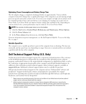
...configuration as the verification of appropriate functionality of the computer and all nonstandard, third-party hardware components integrated through Dell Software and Peripherals, Readyware, and Custom Factory Integration2. 1 Repair services are covered by the original manufacturer, ...Dell also extends a parts replacement program to the terms and conditions of time and your battery is available at high processor speeds and system activity levels. Low Power Mode can also click the power meter icon on and running your computer. To access the help file, see the Dell Inspiron...
...configuration as the verification of appropriate functionality of the computer and all nonstandard, third-party hardware components integrated through Dell Software and Peripherals, Readyware, and Custom Factory Integration2. 1 Repair services are covered by the original manufacturer, ...Dell also extends a parts replacement program to the terms and conditions of time and your battery is available at high processor speeds and system activity levels. Low Power Mode can also click the power meter icon on and running your computer. To access the help file, see the Dell Inspiron...

Owner's Manual
Page 90
... A digital device pursuant to be a Class B digital device. Note that FCC regulations provide that is considered to Part 15 of the software program that changes or modifications not expressly approved by Dell not under the Dell brand (printers, scanners, cameras, games, and so on). This equipment generates, uses, and can radiate radio frequency...
... A digital device pursuant to be a Class B digital device. Note that FCC regulations provide that is considered to Part 15 of the software program that changes or modifications not expressly approved by Dell not under the Dell brand (printers, scanners, cameras, games, and so on). This equipment generates, uses, and can radiate radio frequency...


