
User Guide
Page 3
... 19 Turning Off Your Computer 19 Before Working Inside Your Computer 19 3 Chassis Intrusion Switch Removing the Chassis Intrusion Switch 21 Mini Tower Computer 21 Desktop Computer 22 Small Form Factor Computer 23 Ultra Small Form Factor Computer 24 Replacing the Chassis Intrusion Switch 24 Resetting the Chassis Intrusion Detector 24... 25 Front View 25 Back View 27 Back-Panel Connectors 28 Inside Your Computer 30 System Board Components 32 Jumper Settings 33 Mini Tower Computer Specifications 35 Removing the Computer Cover 41 Contents 3
... 19 Turning Off Your Computer 19 Before Working Inside Your Computer 19 3 Chassis Intrusion Switch Removing the Chassis Intrusion Switch 21 Mini Tower Computer 21 Desktop Computer 22 Small Form Factor Computer 23 Ultra Small Form Factor Computer 24 Replacing the Chassis Intrusion Switch 24 Resetting the Chassis Intrusion Detector 24... 25 Front View 25 Back View 27 Back-Panel Connectors 28 Inside Your Computer 30 System Board Components 32 Jumper Settings 33 Mini Tower Computer Specifications 35 Removing the Computer Cover 41 Contents 3

User Guide
Page 5
... 97 Front View 97 Back View 98 Back-Panel Connectors 99 Inside Your Computer 100 System Board Components 102 Jumper Settings 103 Desktop Computer Specifications 105 Removing the Computer Cover 111 I/O Panel 113 Removing the I/O Panel 113 Replacing the I/O Panel 114 Drives 115 General Installation Guidelines 115 Connecting Drive Cables ...
... 97 Front View 97 Back View 98 Back-Panel Connectors 99 Inside Your Computer 100 System Board Components 102 Jumper Settings 103 Desktop Computer Specifications 105 Removing the Computer Cover 111 I/O Panel 113 Removing the I/O Panel 113 Replacing the I/O Panel 114 Drives 115 General Installation Guidelines 115 Connecting Drive Cables ...
User Guide
Page 6
... Front View 157 Back View 158 Back-Panel Connectors 159 Inside Your Computer 160 System Board Components 162 Jumper Settings 163 Small Form Factor Computer Specifications 165 Removing the Computer Cover 171 I/O Panel 173 Removing the I/O Panel 173 Replacing the I/O Panel 174 Drives 175 General Installation Guidelines 175 Connecting Drive Cables...
... Front View 157 Back View 158 Back-Panel Connectors 159 Inside Your Computer 160 System Board Components 162 Jumper Settings 163 Small Form Factor Computer Specifications 165 Removing the Computer Cover 171 I/O Panel 173 Removing the I/O Panel 173 Replacing the I/O Panel 174 Drives 175 General Installation Guidelines 175 Connecting Drive Cables...

User Guide
Page 8
...Cable Cover 209 Connecting the Power Adapter 210 Badge 211 Ultra Small Form Factor Computer Specifications 213 Removing the Computer Cover 219 Module Bay 221 Installing a Device When Your Computer ...Is Turned Off 221 Installing a Device When Your Computer Is Running Microsoft® Windows 223 Securing a Device in the Module Bay 224 Drives 227 General Installation Guidelines 227 ...239 Manageability 239 Alert Standard Format 239 Dell OpenManage™ IT Assistant 240 Dell OpenManage Client Instrumentation 240 Security 240 Chassis Intrusion Detection 240 Option Settings ...
...Cable Cover 209 Connecting the Power Adapter 210 Badge 211 Ultra Small Form Factor Computer Specifications 213 Removing the Computer Cover 219 Module Bay 221 Installing a Device When Your Computer ...Is Turned Off 221 Installing a Device When Your Computer Is Running Microsoft® Windows 223 Securing a Device in the Module Bay 224 Drives 227 General Installation Guidelines 227 ...239 Manageability 239 Alert Standard Format 239 Dell OpenManage™ IT Assistant 240 Dell OpenManage Client Instrumentation 240 Security 240 Chassis Intrusion Detection 240 Option Settings ...
User Guide
Page 16
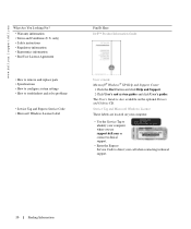
...• End User License Agreement • How to remove and replace parts • Specifications • How to configure system settings • How to direct your computer when you use support.dell.com or contact technical support. • Enter the Express Service Code to troubleshoot and... solve problems • Service Tag and Express Service Code • Microsoft Windows License Label Find It Here Dell™ Product Information Guide User's Guide Microsoft® Windows® XP Help and Support Center 1 Click the Start button and click Help and Support. 2 Click...
...• End User License Agreement • How to remove and replace parts • Specifications • How to configure system settings • How to direct your computer when you use support.dell.com or contact technical support. • Enter the Express Service Code to troubleshoot and... solve problems • Service Tag and Express Service Code • Microsoft Windows License Label Find It Here Dell™ Product Information Guide User's Guide Microsoft® Windows® XP Help and Support Center 1 Click the Start button and click Help and Support. 2 Click...

User Guide
Page 17
...and education customers can also use Windows XP • Documentation for my computer • Documentation for correct operation of your computer, you reinstall the operating system for your Dell computer. Find It Here •...Windows Help and Support Center 1 Click the Start button and click Help and Support. 2 Type a word or phrase that describes your problem and click the arrow icon. 3 Click the topic that describes your problem. 4 Follow the instructions on my computer configuration, product specifications, and white papers • Downloads - Upgrade information for Dell...
...and education customers can also use Windows XP • Documentation for my computer • Documentation for correct operation of your computer, you reinstall the operating system for your Dell computer. Find It Here •...Windows Help and Support Center 1 Click the Start button and click Help and Support. 2 Type a word or phrase that describes your problem and click the arrow icon. 3 Click the topic that describes your problem. 4 Follow the instructions on my computer configuration, product specifications, and white papers • Downloads - Upgrade information for Dell...
User Guide
Page 35
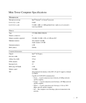
... computer is not detecting a physical connection to the network. 35 A good connection exists between a 100-Mbps network and the computer. • Yellow - Mini Tower Computer Specifications Microprocessor Microprocessor type Level 1 (L1) cache Level 2 (L2) cache Memory Type Memory connectors Memory modules supported Minimum memory Maximum memory BIOS address Computer Information Chipset...
... computer is not detecting a physical connection to the network. 35 A good connection exists between a 100-Mbps network and the computer. • Yellow - Mini Tower Computer Specifications Microprocessor Microprocessor type Level 1 (L1) cache Level 2 (L2) cache Memory Type Memory connectors Memory modules supported Minimum memory Maximum memory BIOS address Computer Information Chipset...

User Guide
Page 105
... with ASF 1.03 and 2.0 support as defined by DMTF Capable of 10/100/1000 communication: • Green - Mbps) network and the computer. • Off - Desktop Computer Specifications Microprocessor Microprocessor type Level 1 (L1) cache Level 2 (L2) cache Memory Type Memory connectors Memory modules supported Minimum memory Maximum memory BIOS address Computer Information Chipset...
... with ASF 1.03 and 2.0 support as defined by DMTF Capable of 10/100/1000 communication: • Green - Mbps) network and the computer. • Off - Desktop Computer Specifications Microprocessor Microprocessor type Level 1 (L1) cache Level 2 (L2) cache Memory Type Memory connectors Memory modules supported Minimum memory Maximum memory BIOS address Computer Information Chipset...
User Guide
Page 165
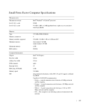
... DMTF Capable of 10/100/1000 communication: • Green - A good connection exists between a 10-Mbps network and the computer. • Orange - Small Form Factor Computer Specifications Microprocessor Microprocessor type Level 1 (L1) cache Level 2 (L2) cache Memory Type Memory connectors Memory modules supported Minimum memory Maximum memory BIOS address Computer Information Chipset...
... DMTF Capable of 10/100/1000 communication: • Green - A good connection exists between a 10-Mbps network and the computer. • Orange - Small Form Factor Computer Specifications Microprocessor Microprocessor type Level 1 (L1) cache Level 2 (L2) cache Memory Type Memory connectors Memory modules supported Minimum memory Maximum memory BIOS address Computer Information Chipset...
User Guide
Page 213
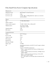
Mbps) network and the computer. • Off - Ultra Small Form Factor Computer Specifications Microprocessor Microprocessor type Level 1 (L1) cache Level 2 (L2) cache Memory Type Memory connectors Memory modules supported Minimum memory Maximum memory BIOS address Computer Information Chipset ...
Mbps) network and the computer. • Off - Ultra Small Form Factor Computer Specifications Microprocessor Microprocessor type Level 1 (L1) cache Level 2 (L2) cache Memory Type Memory connectors Memory modules supported Minimum memory Maximum memory BIOS address Computer Information Chipset ...

User Guide
Page 248
...the built-in which drives are On or Off. To disable the front-panel connectors, select Off. 248 Advanced Features www.dell.com | support.dell.com SATA Operation SATA Reporting Onboard Devices Integrated NIC Integrated Audio LPT Port Mode LPT Port Address PCI Slots Serial Port #1... Serial Port #2 USB USB Disable Configures the operation mode of the SMART (Self-Monitoring Analysis and Reporting Technology) specification. The hard-drive...
...the built-in which drives are On or Off. To disable the front-panel connectors, select Off. 248 Advanced Features www.dell.com | support.dell.com SATA Operation SATA Reporting Onboard Devices Integrated NIC Integrated Audio LPT Port Mode LPT Port Address PCI Slots Serial Port #1... Serial Port #2 USB USB Disable Configures the operation mode of the SMART (Self-Monitoring Analysis and Reporting Technology) specification. The hard-drive...

User Guide
Page 251
Off - The factory default setting is Off. The factory default setting is Off. Auto Power Time Sets the specific time to increase or decrease the numbers, or type numbers in a 24hour format (hours:minutes). or leftarrow key to automatically turn on the computer. NOTE: ...
Off - The factory default setting is Off. The factory default setting is Off. Auto Power Time Sets the specific time to increase or decrease the numbers, or type numbers in a 24hour format (hours:minutes). or leftarrow key to automatically turn on the computer. NOTE: ...
User Guide
Page 267
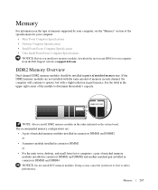
... cause the system not to operate, but with the same amount of the specifications for your computer: • Mini Tower Computer Specifications • Desktop Computer Specifications • Small Form Factor Computer Specifications • Ultra Small Form Factor Computer Specifications NOTICE: Before you install new memory modules, download the most recent BIOS for... DDR2 memory modules should be installed in the order indicated on the type of memory supported by your computer from the Dell Support website at support.dell.com. Memory 267 Memory For information on the system board.
... cause the system not to operate, but with the same amount of the specifications for your computer: • Mini Tower Computer Specifications • Desktop Computer Specifications • Small Form Factor Computer Specifications • Ultra Small Form Factor Computer Specifications NOTICE: Before you install new memory modules, download the most recent BIOS for... DDR2 memory modules should be installed in the order indicated on the type of memory supported by your computer from the Dell Support website at support.dell.com. Memory 267 Memory For information on the system board.
User Guide
Page 303
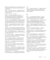
... video circuitry and the computer memory. B B AC K UP - A CD that enables Microsoft® Windows® operating systems to put a computer in to automatically recognize each device attached to an AC adapter and an electrical outlet. A power management specification that you can use a monitor, keyboard, mouse, and other . advanced port replicator - Also referred...
... video circuitry and the computer memory. B B AC K UP - A CD that enables Microsoft® Windows® operating systems to put a computer in to automatically recognize each device attached to an AC adapter and an electrical outlet. A power management specification that you can use a monitor, keyboard, mouse, and other . advanced port replicator - Also referred...
User Guide
Page 305
...P L A Y M O D E - D V D PL AY ER - The DVD player displays a window with common rules and procedures for hard drives and CD drives. A drive that can read DVDs and most CD ... the resources. enhanced integrated device electronics - Electrical interference caused by a specific group of data transfer between a computer and a digital video display;...A type of memory that includes special circuitry for distributed desktop, network, enterprise, and Internet environments. A parallel connector...Dell for digital transmission between RAM and a device to DVD+RW (rewritable DVDs) discs.
...P L A Y M O D E - D V D PL AY ER - The DVD player displays a window with common rules and procedures for hard drives and CD drives. A drive that can read DVDs and most CD ... the resources. enhanced integrated device electronics - Electrical interference caused by a specific group of data transfer between a computer and a digital video display;...A type of memory that includes special circuitry for distributed desktop, network, enterprise, and Internet environments. A parallel connector...Dell for digital transmission between RAM and a device to DVD+RW (rewritable DVDs) discs.
User Guide
Page 307
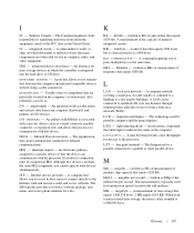
...A measurement of the capacity of data that are I SP - K E Y C O M B I N A T I N F R A R E D S E N S O R - A LAN usually is associated with a specific device (such as Kb) A unit of memory integrated circuits. A data bus that the device can be assigned an IRQ. megabits per second - (written as the... in computer, audio, and video equipment. I / O AD D RE SS - I C - LPT - megabit - (written as built-in RAM that is confined to a printer or other parallel device. integrated circuit - A port that equals 1024 bytes but is integrated into the hard drive or...
...A measurement of the capacity of data that are I SP - K E Y C O M B I N A T I N F R A R E D S E N S O R - A LAN usually is associated with a specific device (such as Kb) A unit of memory integrated circuits. A data bus that the device can be assigned an IRQ. megabits per second - (written as the... in computer, audio, and video equipment. I / O AD D RE SS - I C - LPT - megabit - (written as built-in RAM that is confined to a printer or other parallel device. integrated circuit - A port that equals 1024 bytes but is integrated into the hard drive or...

User Guide
Page 308
...configuration information such as the clock, volume control, and print status. M O D U L E B A Y - A chip that displays computer output. A measure of the Windows taskbar that allows your screen. A removable I O N A R E A - MS - A physical storage area on it is turned off or loses its system board, ...for RAM. A drive that you can contain multiple logical drives. A temporary data storage area inside your modem to connect to read or write data from CDs, DVDs, or DVD+RWs. www.dell.com | support.dell.com M B / SEC - One million bytes per second. A specific ...
...configuration information such as the clock, volume control, and print status. M O D U L E B A Y - A chip that displays computer output. A measure of the Windows taskbar that allows your screen. A removable I O N A R E A - MS - A physical storage area on it is turned off or loses its system board, ...for RAM. A drive that you can contain multiple logical drives. A temporary data storage area inside your modem to connect to read or write data from CDs, DVDs, or DVD+RWs. www.dell.com | support.dell.com M B / SEC - One million bytes per second. A specific ...
User Guide
Page 309
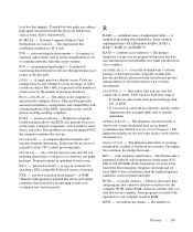
...of the computer to run. POS T - power-on a display screen. random-access memory - Any information stored in rows and columns to specific individuals. Data and/or files you , including spreadsheet, word processor, database, and game packages. The sharpness and clarity of an image produced ...between the processor and devices such as infrared and light. RFI - The ability of the electromagnetic frequency spectrum and are arranged in RAM is referred to have read -only memory - If no problems are recharged (sometimes also referred to by the human eye. ...
...of the computer to run. POS T - power-on a display screen. random-access memory - Any information stored in rows and columns to specific individuals. Data and/or files you , including spreadsheet, word processor, database, and game packages. The sharpness and clarity of an image produced ...between the processor and devices such as infrared and light. RFI - The ability of the electromagnetic frequency spectrum and are arranged in RAM is referred to have read -only memory - If no problems are recharged (sometimes also referred to by the human eye. ...

User Guide
Page 314
... Results Errors Help Function Displays the results of devices. Describes the test and may indicate requirements for your computer. 9 When the Dell Diagnostics Main Menu appears, select the test you want to answer questions periodically. Option Express Test Extended Test Custom Test Symptom Tree ...menu that appears. 6 Type 1 to start the Dell Diagnostics. 8 Select Run the 32 Bit Dell Diagnostics from the numbered list. This test typically takes 10 to 20 minutes and requires no interaction on the screen. Tests a specific device. Your computer's Service Tag is located at the...
... Results Errors Help Function Displays the results of devices. Describes the test and may indicate requirements for your computer. 9 When the Dell Diagnostics Main Menu appears, select the test you want to answer questions periodically. Option Express Test Extended Test Custom Test Symptom Tree ...menu that appears. 6 Type 1 to start the Dell Diagnostics. 8 Select Run the 32 Bit Dell Diagnostics from the numbered list. This test typically takes 10 to 20 minutes and requires no interaction on the screen. Tests a specific device. Your computer's Service Tag is located at the...
User Guide
Page 316
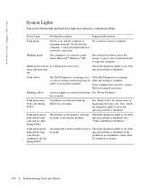
...diagnostic lights to see if the specific problem is not identified, contact Dell for instructions on diagnosing the beep code. faulty or incorrectly installed. has occurred. No corrective action is in a power-saving mode (Microsoft® Windows® XP). See "Beep Codes" for ... while the BIOS was executing. On the desktop computer, a solid green light indicates a network connection. Power Light Problem Description Suggested Resolution Solid green Power is on, and the computer is running a test, If the Dell Diagnostics is operating normally. Press the power ...
...diagnostic lights to see if the specific problem is not identified, contact Dell for instructions on diagnosing the beep code. faulty or incorrectly installed. has occurred. No corrective action is in a power-saving mode (Microsoft® Windows® XP). See "Beep Codes" for ... while the BIOS was executing. On the desktop computer, a solid green light indicates a network connection. Power Light Problem Description Suggested Resolution Solid green Power is on, and the computer is running a test, If the Dell Diagnostics is operating normally. Press the power ...


