
User Guide
Page 4
... Port Adapters 78 Installing a Serial Port Adapter 78 Removing a Serial Port Adapter 80 Power Supply 83 Replacing the Power Supply 83 DC Power Connectors 85 Processor 91 Removing the Processor 91 Installing the Processor 92 4 Contents
... Port Adapters 78 Installing a Serial Port Adapter 78 Removing a Serial Port Adapter 80 Power Supply 83 Replacing the Power Supply 83 DC Power Connectors 85 Processor 91 Removing the Processor 91 Installing the Processor 92 4 Contents
User Guide
Page 6
... Removing a Serial Port Adapter From the Riser-Card Cage 142 Power Supply 145 Replacing the Power Supply 145 DC Power Connectors 147 Processor 153 Removing the Processor 153 Installing the Processor 154 6 Small Form Factor Computer About Your Small Form Factor Computer 157 Front View 157 Back View 158 Back-Panel Connectors 159...
... Removing a Serial Port Adapter From the Riser-Card Cage 142 Power Supply 145 Replacing the Power Supply 145 DC Power Connectors 147 Processor 153 Removing the Processor 153 Installing the Processor 154 6 Small Form Factor Computer About Your Small Form Factor Computer 157 Front View 157 Back View 158 Back-Panel Connectors 159...

User Guide
Page 7
... Removing a PCI Express Card 193 Serial Port Adapters 193 Installing a Serial Port Adapter 194 Removing a Serial Port Adapter 194 Power Supply 195 Processor 197 Removing the Processor 197 Installing the Processor 198 7 Ultra Small Form Factor Computer About Your Ultra Small Form Factor Computer 201 Front View 201 Side View 202 Back View...
... Removing a PCI Express Card 193 Serial Port Adapters 193 Installing a Serial Port Adapter 194 Removing a Serial Port Adapter 194 Power Supply 195 Processor 197 Removing the Processor 197 Installing the Processor 198 7 Ultra Small Form Factor Computer About Your Ultra Small Form Factor Computer 201 Front View 201 Side View 202 Back View...

User Guide
Page 8
...221 Installing a Device When Your Computer Is Turned Off 221 Installing a Device When Your Computer Is Running Microsoft® Windows 223 Securing a Device in the Module Bay 224 Drives 227 General Installation Guidelines 227 Connecting Drive Cables 227 Drive Interface... Drive Cables 228 Hard Drive 229 Installing a Hard Drive 229 Processor 233 8 Advanced Features LegacySelect Technology Control 239 Manageability 239 Alert Standard Format 239 Dell OpenManage™ IT Assistant 240 Dell OpenManage Client Instrumentation 240 Security 240 Chassis Intrusion Detection 240 Option ...
...221 Installing a Device When Your Computer Is Turned Off 221 Installing a Device When Your Computer Is Running Microsoft® Windows 223 Securing a Device in the Module Bay 224 Drives 227 General Installation Guidelines 227 Connecting Drive Cables 227 Drive Interface... Drive Cables 228 Hard Drive 229 Installing a Hard Drive 229 Processor 233 8 Advanced Features LegacySelect Technology Control 239 Manageability 239 Alert Standard Format 239 Dell OpenManage™ IT Assistant 240 Dell OpenManage Client Instrumentation 240 Security 240 Chassis Intrusion Detection 240 Option ...

User Guide
Page 17
...M processors, optical drives, and USB devices. Find It Here • Solutions - Contact information, service call status and support history, service contract, online discussions with other Dell customers site. • Upgrades - Certified drivers, patches, and software updates • Desktop System ...support.dell.com technicians, online courses, frequently asked questions NOTE: Select your computer, you should also reinstall the DSS utility. Service call and order status, warranty, and repair information NOTE: Corporate, government, and education customers can also use Windows XP ...
...M processors, optical drives, and USB devices. Find It Here • Solutions - Contact information, service call status and support history, service contract, online discussions with other Dell customers site. • Upgrades - Certified drivers, patches, and software updates • Desktop System ...support.dell.com technicians, online courses, frequently asked questions NOTE: Select your computer, you should also reinstall the DSS utility. Service call and order status, warranty, and repair information NOTE: Corporate, government, and education customers can also use Windows XP ...

User Guide
Page 19
..." and "Before Working Inside Your Computer." • You have read the safety information in your Dell™ Product Information Guide. • A component can be replaced by performing the removal procedure in... its metal mounting bracket. If your own personal safety. b In the Turn off computer window, click Turn off . CAUTION: Handle components and cards with care. Recommended Tools The procedures...when you begin any attached devices are turned off . Hold a component such as a processor by its edges, not by its pins. Unless otherwise noted, each procedure assumes that ...
..." and "Before Working Inside Your Computer." • You have read the safety information in your Dell™ Product Information Guide. • A component can be replaced by performing the removal procedure in... its metal mounting bracket. If your own personal safety. b In the Turn off computer window, click Turn off . CAUTION: Handle components and cards with care. Recommended Tools The procedures...when you begin any attached devices are turned off . Hold a component such as a processor by its edges, not by its pins. Unless otherwise noted, each procedure assumes that ...

User Guide
Page 33
1 fan connector (FAN) 12 password jumper (PSWD) 2 processor connector (CPU) 13 battery socket (BATT) 3 power connector (12VPOWER) 14 PCI Express x16 connector (SLOT1) 4 memory module connectors (DIMM_1, DIMM_2, 15 PCI Express x1 connector (...
1 fan connector (FAN) 12 password jumper (PSWD) 2 processor connector (CPU) 13 battery socket (BATT) 3 power connector (12VPOWER) 14 PCI Express x16 connector (SLOT1) 4 memory module connectors (DIMM_1, DIMM_2, 15 PCI Express x1 connector (...
User Guide
Page 35
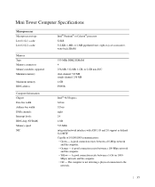
... Information Chipset Data bus width Address bus width DMA channels Interrupt levels BIOS chip (NVRAM) Memory speed NIC Intel® Pentium® or Celeron® processor 32 KB 512-KB, 1-MB, or 2-MB pipelined-burst, eight-way set associative, write-back SRAM 533-MHz DDR2 SDRAM 4 256-MB, 512-MB, 1-GB...
... Information Chipset Data bus width Address bus width DMA channels Interrupt levels BIOS chip (NVRAM) Memory speed NIC Intel® Pentium® or Celeron® processor 32 KB 512-KB, 1-MB, or 2-MB pipelined-burst, eight-way set associative, write-back SRAM 533-MHz DDR2 SDRAM 4 256-MB, 512-MB, 1-GB...

User Guide
Page 91
... body before you touch it. 3 Rotate the heat sink assembly upward, and remove it from your computer's electronic components. Processor CAUTION: Before you touch any of the heat sink assembly. Removing the Processor 1 Follow the procedures in "Before You Begin." 2 Loosen the captive screw on the computer chassis. CAUTION: Despite having a plastic...
... body before you touch it. 3 Rotate the heat sink assembly upward, and remove it from your computer's electronic components. Processor CAUTION: Before you touch any of the heat sink assembly. Removing the Processor 1 Follow the procedures in "Before You Begin." 2 Loosen the captive screw on the computer chassis. CAUTION: Despite having a plastic...

User Guide
Page 92
... heat sink. If you are not installing a processor upgrade kit from Dell, reuse the original heat sink when you are installing a processor upgrade kit from Dell, remove the heat sink assembly from the socket. www.dell.com | support.dell.com NOTICE: If you install your new processor. 4 Open the processor cover by touching an unpainted metal surface on...
... heat sink. If you are not installing a processor upgrade kit from Dell, reuse the original heat sink when you are installing a processor upgrade kit from Dell, remove the heat sink assembly from the socket. www.dell.com | support.dell.com NOTICE: If you install your new processor. 4 Open the processor cover by touching an unpainted metal surface on...

User Guide
Page 93
...any objects to touch the underside of the processor and socket. 2 1 3 9 4 5 6 8 1 processor cover 2 tab 3 processor 4 processor socket 5 center cover latch 7 6 release lever 7 front alignment-notch 8 socket and processor pin-1 indicator 9 rear alignment-notch 93 NOTE: You must position the processor correctly in the socket to avoid permanent ... socket is not fully extended, move it to that position. 4 Orient the front and rear alignment-notches on the processor with the front and rear alignmentnotches on the pins in the socket. 1 Follow the procedures in "Before You Begin." 2 Unpack ...
...any objects to touch the underside of the processor and socket. 2 1 3 9 4 5 6 8 1 processor cover 2 tab 3 processor 4 processor socket 5 center cover latch 7 6 release lever 7 front alignment-notch 8 socket and processor pin-1 indicator 9 rear alignment-notch 93 NOTE: You must position the processor correctly in the socket to avoid permanent ... socket is not fully extended, move it to that position. 4 Orient the front and rear alignment-notches on the processor with the front and rear alignmentnotches on the pins in the socket. 1 Follow the procedures in "Before You Begin." 2 Unpack ...

User Guide
Page 94
... heat sink assembly back onto the heat-sink assembly bracket. If you installed a processor replacement kit from Dell, remove the original heat sink assembly from Dell, reuse the original heat sink assembly when you replace the processor. NOTICE: If you are not installing a processor upgrade kit from the shroud and return it into place to...
... heat sink assembly back onto the heat-sink assembly bracket. If you installed a processor replacement kit from Dell, remove the original heat sink assembly from Dell, reuse the original heat sink assembly when you replace the processor. NOTICE: If you are not installing a processor upgrade kit from the shroud and return it into place to...

User Guide
Page 103
1 fan connector (FAN) 12 password jumper (PSWD) 2 processor connector (CPU) 13 battery socket (BATT) 3 power connector (12VPOWER) 14 PCI Express x16 connector (SLOT1) 4 memory module connectors (DIMM_1, DIMM_2, 15 PCI connector (SLOT3) DIMM_3, ... board speaker (BEEP) 10 RTC reset jumper (RTCRST) 21 internal speaker (INT_SPKR) 11 intrusion switch connector (INTRUDER) Jumper Settings The jumper locations are shown below. Desktop Computer Desktop Computer 103
1 fan connector (FAN) 12 password jumper (PSWD) 2 processor connector (CPU) 13 battery socket (BATT) 3 power connector (12VPOWER) 14 PCI Express x16 connector (SLOT1) 4 memory module connectors (DIMM_1, DIMM_2, 15 PCI connector (SLOT3) DIMM_3, ... board speaker (BEEP) 10 RTC reset jumper (RTCRST) 21 internal speaker (INT_SPKR) 11 intrusion switch connector (INTRUDER) Jumper Settings The jumper locations are shown below. Desktop Computer Desktop Computer 103

User Guide
Page 105
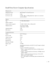
...8226; Yellow - The computer is not detecting a physical connection to the network. 105 A good connection exists between a 1-Gb (or 1000- Desktop Computer Specifications Microprocessor Microprocessor type Level 1 (L1) cache Level 2 (L2) cache Memory Type Memory connectors Memory modules supported Minimum memory Maximum memory BIOS... bus width Address bus width DMA channels Interrupt levels BIOS chip (NVRAM) Memory speed NIC Intel® Pentium® or Celeron® processor 32 KB 512-KB, 1-MB, or 2-MB pipelined-burst, eight-way set associative, write-back SRAM 533-MHz DDR2 SDRAM 4 256...
...8226; Yellow - The computer is not detecting a physical connection to the network. 105 A good connection exists between a 1-Gb (or 1000- Desktop Computer Specifications Microprocessor Microprocessor type Level 1 (L1) cache Level 2 (L2) cache Memory Type Memory connectors Memory modules supported Minimum memory Maximum memory BIOS... bus width Address bus width DMA channels Interrupt levels BIOS chip (NVRAM) Memory speed NIC Intel® Pentium® or Celeron® processor 32 KB 512-KB, 1-MB, or 2-MB pipelined-burst, eight-way set associative, write-back SRAM 533-MHz DDR2 SDRAM 4 256...

User Guide
Page 153
You can do so by touching an unpainted metal surface on each side of the heat sink assembly. Removing the Processor 1 Follow the procedures in the Product Information Guide. Be sure that it has had sufficient time to components inside your...assembly 2 captive screw housing (2) NOTICE: If you are installing a processor upgrade kit from Dell, reuse the original heat sink when you are not installing a processor upgrade kit from Dell, discard the original heat sink. If you install your new processor. 153 Processor CAUTION: Before you touch any of the procedures in this section, follow...
You can do so by touching an unpainted metal surface on each side of the heat sink assembly. Removing the Processor 1 Follow the procedures in the Product Information Guide. Be sure that it has had sufficient time to components inside your...assembly 2 captive screw housing (2) NOTICE: If you are installing a processor upgrade kit from Dell, reuse the original heat sink when you are not installing a processor upgrade kit from Dell, discard the original heat sink. If you install your new processor. 153 Processor CAUTION: Before you touch any of the procedures in this section, follow...

User Guide
Page 154
... the socket. Leave the release lever extended in "Before You Begin." 2 Unpack the new processor, being careful not to fall on the back of the processor. 154 www.dell.com | support.dell.com 4 Open the processor cover by touching an unpainted metal surface on the pins in the socket. 1 Follow the ...procedures in the release position so that the socket is ready for the new processor. Then pull the lever back...
... the socket. Leave the release lever extended in "Before You Begin." 2 Unpack the new processor, being careful not to fall on the back of the processor. 154 www.dell.com | support.dell.com 4 Open the processor cover by touching an unpainted metal surface on the pins in the socket. 1 Follow the ...procedures in the release position so that the socket is ready for the new processor. Then pull the lever back...

User Guide
Page 155
... rear alignmentnotches on the socket. 5 Align the pin-1 corners of the processor and socket. 2 1 3 9 4 5 6 8 7 1 processor cover 2 tab 3 processor 4 processor socket 5 center cover latch 6 release lever 7 front alignment-notch 8 socket and processor pin-1 indicator 9 rear alignment-notch NOTICE: To avoid damage, ensure that the processor aligns properly with the socket, and do not use excessive force when...
... rear alignmentnotches on the socket. 5 Align the pin-1 corners of the processor and socket. 2 1 3 9 4 5 6 8 7 1 processor cover 2 tab 3 processor 4 processor socket 5 center cover latch 6 release lever 7 front alignment-notch 8 socket and processor pin-1 indicator 9 rear alignment-notch NOTICE: To avoid damage, ensure that the processor aligns properly with the socket, and do not use excessive force when...

User Guide
Page 156
... Ensure that the tab on the processor cover is correctly seated and secure. 1 2 3 1 heat sink assembly 2 heat-sink assembly bracket 3 captive screw housing (2) 10 Replace the computer cover. 156 If you installed a processor replacement kit from Dell, reuse the original heat sink assembly ...when you are not installing a processor upgrade kit from Dell, return the original heat sink assembly and processor to secure the processor. b Rotate the heat sink assembly down towards...
... Ensure that the tab on the processor cover is correctly seated and secure. 1 2 3 1 heat sink assembly 2 heat-sink assembly bracket 3 captive screw housing (2) 10 Replace the computer cover. 156 If you installed a processor replacement kit from Dell, reuse the original heat sink assembly ...when you are not installing a processor upgrade kit from Dell, return the original heat sink assembly and processor to secure the processor. b Rotate the heat sink assembly down towards...

User Guide
Page 163
1 fan connector (FAN) 10 intrusion switch connector (INTRUDER) 2 processor connector (CPU) 11 password jumper (PSWD) 3 power connector (12VPOWER) 12 battery socket (BATT) 4 memory module connectors (DIMM_1, DIMM_2, 13 PCI Express x16 connector (SLOT1) DIMM_3, ...
1 fan connector (FAN) 10 intrusion switch connector (INTRUDER) 2 processor connector (CPU) 11 password jumper (PSWD) 3 power connector (12VPOWER) 12 battery socket (BATT) 4 memory module connectors (DIMM_1, DIMM_2, 13 PCI Express x16 connector (SLOT1) DIMM_3, ...
User Guide
Page 165
... Information Chipset Data bus width Address bus width DMA channels Interrupt levels BIOS chip (NVRAM) Memory speed NIC Intel® Pentium® or Celeron® processor 32 KB 512-KB, 1-MB, or 2-MB pipelined-burst, eight-way set associative, write-back SRAM 533-MHz DDR2 SDRAM 4 256-MB, 512-MB, 1-GB...
... Information Chipset Data bus width Address bus width DMA channels Interrupt levels BIOS chip (NVRAM) Memory speed NIC Intel® Pentium® or Celeron® processor 32 KB 512-KB, 1-MB, or 2-MB pipelined-burst, eight-way set associative, write-back SRAM 533-MHz DDR2 SDRAM 4 256-MB, 512-MB, 1-GB...


