Quick Reference Guide
Page 2
...Trademarks used in this document to refer to either potential damage to hardware or loss of data and tells you make better use of Dell Inc.; Notes, Notices, and Cautions NOTE: A NOTE indicates important information that helps you how to avoid the problem. The Quick ...document is strictly forbidden. Intel and Pentium are registered trademarks of Dell Inc. Models DCTR, DCNE, DCSM August 2006 P/N R9729 Rev. A02 If you purchased a Dell™ n Series computer, any references in this text: Dell, OptiPlex, and the DELL logo are optional and may be used in this document to...
...Trademarks used in this document to refer to either potential damage to hardware or loss of data and tells you make better use of Dell Inc.; Notes, Notices, and Cautions NOTE: A NOTE indicates important information that helps you how to avoid the problem. The Quick ...document is strictly forbidden. Intel and Pentium are registered trademarks of Dell Inc. Models DCTR, DCNE, DCSM August 2006 P/N R9729 Rev. A02 If you purchased a Dell™ n Series computer, any references in this text: Dell, OptiPlex, and the DELL logo are optional and may be used in this document to...
Quick Reference Guide
Page 3
... Tower Computer 23 Desktop Computer 24 Small Form Factor Computer 25 Setting Up Your Computer 25 Solving Problems 28 Dell Diagnostics 28 System Lights 31 Diagnostic Lights 32 Beep Codes 35 Running the Dell™ IDE Hard Drive Diagnostics 36 Resolving Software and Hardware Incompatibilities 36 Using Microsoft® Windows® XP...
... Tower Computer 23 Desktop Computer 24 Small Form Factor Computer 25 Setting Up Your Computer 25 Solving Problems 28 Dell Diagnostics 28 System Lights 31 Diagnostic Lights 32 Beep Codes 35 Running the Dell™ IDE Hard Drive Diagnostics 36 Resolving Software and Hardware Incompatibilities 36 Using Microsoft® Windows® XP...
Quick Reference Guide
Page 5
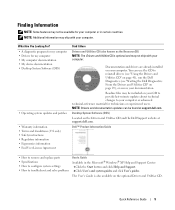
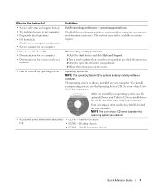
... Utilities CD. Documentation and drivers are already installed on the Drivers and Utilities CD and the Dell Support website at support.dell.com. Desktop System Software (DSS) Located on your computer. Dell™ Product Information Guide • How to remove and replace parts • Specifications •... and click Help and Support. 2 Click User's and system guides and click User's guides. Readme files may be found at support.dell.com. The User's Guide is optional and may ship with your computer. NOTE: Additional information may not ship with your CD to provide...
... Utilities CD. Documentation and drivers are already installed on the Drivers and Utilities CD and the Dell Support website at support.dell.com. Desktop System Software (DSS) Located on your computer. Dell™ Product Information Guide • How to remove and replace parts • Specifications •... and click Help and Support. 2 Click User's and system guides and click User's guides. Readme files may be found at support.dell.com. The User's Guide is optional and may ship with your computer. NOTE: Additional information may not ship with your CD to provide...
Quick Reference Guide
Page 6
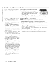
... • Downloads - Contact information, service call status • User guides - www.dell.com | support.dell.com What Are You Looking For? Troubleshooting hints and Dell Support Website - Hints and tips, articles from technicians, online NOTE: Select your region ... and product specifications and support history, service contract, online discussions with other Dell customers • Troubleshooting - DSS is necessary for your computer when you reinstall the operating system for Dell™ 3.5-inch USB floppy drives, Intel® Pentium® M processors...
... • Downloads - Contact information, service call status • User guides - www.dell.com | support.dell.com What Are You Looking For? Troubleshooting hints and Dell Support Website - Hints and tips, articles from technicians, online NOTE: Select your region ... and product specifications and support history, service contract, online discussions with other Dell customers • Troubleshooting - DSS is necessary for your computer when you reinstall the operating system for Dell™ 3.5-inch USB floppy drives, Intel® Pentium® M processors...
Quick Reference Guide
Page 7
...• DCTR - To reinstall your computer. Desktop chassis • DCSM - This website may not ship with your computer. premiersupport.dell.com The Dell Premier Support website is optional and may not be available in certain regions. • How to use the optional Drivers and Utilities CD... to reinstall my operating system Operating System CD NOTE: The Operating System CD is customized for my computer Dell Premier Support Website - Find It Here • Service call status and support history • Top technical issues for my computer &#...
...• DCTR - To reinstall your computer. Desktop chassis • DCSM - This website may not ship with your computer. premiersupport.dell.com The Dell Premier Support website is optional and may not be available in certain regions. • How to use the optional Drivers and Utilities CD... to reinstall my operating system Operating System CD NOTE: The Operating System CD is customized for my computer Dell Premier Support Website - Find It Here • Service call status and support history • Top technical issues for my computer &#...
Quick Reference Guide
Page 9
For more information about sleep modes and exiting from a power-saving mode, press the power button or use the keyboard or the mouse if it is in a power-saving mode. • Blinking or solid amber - NOTICE: To avoid losing data, do not turn on the computer. The computer is configured as a mouse, keyboard, memory key, printer, joystick, and computer speakers into either of speakers. See "System Lights" on the back panel for devices that can help you troubleshoot a computer problem based on page 32. This light flickers when the hard drive is established. This light indicates ...
For more information about sleep modes and exiting from a power-saving mode, press the power button or use the keyboard or the mouse if it is in a power-saving mode. • Blinking or solid amber - NOTICE: To avoid losing data, do not turn on the computer. The computer is configured as a mouse, keyboard, memory key, printer, joystick, and computer speakers into either of speakers. See "System Lights" on the back panel for devices that can help you troubleshoot a computer problem based on page 32. This light flickers when the hard drive is established. This light indicates ...
Quick Reference Guide
Page 11
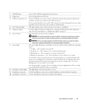
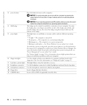
1 cover release latch This latch allows you use the USB connectors on the back panel for devices that typically remain connected, such as a mouse, keyboard, memory key, printer, joystick, and computer speakers into the appropriate connector. 6 card slots You can access connectors for any installed PCI and PCI Express cards. Desktop Computer - It is recommended that you to open the computer cover. 2 padlock ring Insert a padlock to lock the computer cover. 3 voltage selection switch Your computer is established. Quick Reference Guide 11 Front View 1 2 3 11 10 9 8 76 5 4 1 USB...
1 cover release latch This latch allows you use the USB connectors on the back panel for devices that typically remain connected, such as a mouse, keyboard, memory key, printer, joystick, and computer speakers into the appropriate connector. 6 card slots You can access connectors for any installed PCI and PCI Express cards. Desktop Computer - It is recommended that you to open the computer cover. 2 padlock ring Insert a padlock to lock the computer cover. 3 voltage selection switch Your computer is established. Quick Reference Guide 11 Front View 1 2 3 11 10 9 8 76 5 4 1 USB...
Quick Reference Guide
Page 12
...; No light - Use the headphone connector to attach a microphone. Instead, perform an operating system shutdown. This light turns on the diagnostic code. www.dell.com | support.dell.com 3 power button 4 Dell badge 5 power light 6 diagnostic lights 7 hard-drive activity light 8 headphone connector 9 microphone connector 10 floppy drive 11 CD/DVD drive Press this...
...; No light - Use the headphone connector to attach a microphone. Instead, perform an operating system shutdown. This light turns on the diagnostic code. www.dell.com | support.dell.com 3 power button 4 Dell badge 5 power light 6 diagnostic lights 7 hard-drive activity light 8 headphone connector 9 microphone connector 10 floppy drive 11 CD/DVD drive Press this...
Quick Reference Guide
Page 13
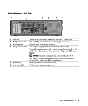
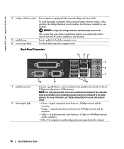
Back View 1 2 3 4 5 6 1 card slots You can access connectors for any installed PCI and PCI Express cards. 2 back-panel connectors Plug serial, USB, and other devices into the appropriate connector. 3 power connector Insert the power cable into this latch to 115-V. NOTICE: In Japan, the voltage selection switch must be set the switch to the voltage that your monitor and attached devices are electrically rated to operate with the AC power available in your location. 5 padlock ring Insert a padlock to lock the computer cover. 6 cover release latch Use this connector. 4 ...
Back View 1 2 3 4 5 6 1 card slots You can access connectors for any installed PCI and PCI Express cards. 2 back-panel connectors Plug serial, USB, and other devices into the appropriate connector. 3 power connector Insert the power cable into this latch to 115-V. NOTICE: In Japan, the voltage selection switch must be set the switch to the voltage that your monitor and attached devices are electrically rated to operate with the AC power available in your location. 5 padlock ring Insert a padlock to lock the computer cover. 6 cover release latch Use this connector. 4 ...
Quick Reference Guide
Page 14
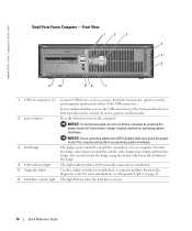
...is established. 5 diagnostic lights Use these lights to help you press the power button the computer will perform an operating system shutdown. 3 Dell badge 4 LAN indicator light The badge can also rotate the badge using the slot provided near the bottom of the USB connectors. www....dell.com | support.dell.com Small Form Factor Computer - NOTICE: If your operating system has ACPI enabled, when you troubleshoot a computer problem based on the computer. Instead...
...is established. 5 diagnostic lights Use these lights to help you press the power button the computer will perform an operating system shutdown. 3 Dell badge 4 LAN indicator light The badge can also rotate the badge using the slot provided near the bottom of the USB connectors. www....dell.com | support.dell.com Small Form Factor Computer - NOTICE: If your operating system has ACPI enabled, when you troubleshoot a computer problem based on the computer. Instead...
Quick Reference Guide
Page 15
To exit from a power-saving mode, see "Power Management" in your online User's Guide. Small Form Factor Computer - Quick Reference Guide 15 The computer is configured as a wake device in a power-saving mode. • Blinking or solid amber - See "Power Problems" in a normal operating state. • Blinking green - For more information about sleep modes and exiting from a power-saving mode, press the power button or use the keyboard or the mouse if it is turned off. • Steady green - Use the microphone connector to indicate different operating states: • No light -...
To exit from a power-saving mode, see "Power Management" in your online User's Guide. Small Form Factor Computer - Quick Reference Guide 15 The computer is configured as a wake device in a power-saving mode. • Blinking or solid amber - See "Power Problems" in a normal operating state. • Blinking green - For more information about sleep modes and exiting from a power-saving mode, press the power button or use the keyboard or the mouse if it is turned off. • Steady green - Use the microphone connector to indicate different operating states: • No light -...
Quick Reference Guide
Page 16
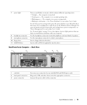
... between a 1-Gbps (or 1000-Mbps) network and the computer. • Off - A good connection exists between a 100-Mbps network and the computer. • Yellow - www.dell.com | support.dell.com 4 voltage selection switch Your computer is automatically disabled if the computer detects an installed card containing a parallel connector configured to the same address...
... between a 1-Gbps (or 1000-Mbps) network and the computer. • Off - A good connection exists between a 100-Mbps network and the computer. • Yellow - www.dell.com | support.dell.com 4 voltage selection switch Your computer is automatically disabled if the computer detects an installed card containing a parallel connector configured to the same address...
Quick Reference Guide
Page 17
If you use Category 5 wiring and connectors for your network. This light flashes yellow when the computer is recommended that you must use the connector on the card. On computers with integrated amplifiers. Connect a serial device, such as a mouse, keyboard, memory key, printer, joystick, and computer speakers into a sound or telephony program. NOTE: Do not plug a telephone cable into the blue connector. Use the green line-out connector to attach headphones and most speakers with a sound card, the microphone connector is on the card. Plug the cable from your computer....
If you use Category 5 wiring and connectors for your network. This light flashes yellow when the computer is recommended that you must use the connector on the card. On computers with integrated amplifiers. Connect a serial device, such as a mouse, keyboard, memory key, printer, joystick, and computer speakers into a sound or telephony program. NOTE: Do not plug a telephone cable into the blue connector. Use the green line-out connector to attach headphones and most speakers with a sound card, the microphone connector is on the card. Plug the cable from your computer....
Quick Reference Guide
Page 18
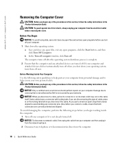
CAUTION: To guard against electrical shock, always unplug your computer from potential damage and to servicing that is not authorized by Dell is not covered by your warranty. NOTICE: Only a certified service technician should perform repairs on the cable itself. Some cables have a ... loop, not on your computer and then unplug it is complete. 2 Ensure that both connectors are correctly oriented and aligned. www.dell.com | support.dell.com Removing the Computer Cover CAUTION: Before you begin any of the procedures in this section, follow the safety instructions in the Product...
CAUTION: To guard against electrical shock, always unplug your computer from potential damage and to servicing that is not authorized by Dell is not covered by your warranty. NOTICE: Only a certified service technician should perform repairs on the cable itself. Some cables have a ... loop, not on your computer and then unplug it is complete. 2 Ensure that both connectors are correctly oriented and aligned. www.dell.com | support.dell.com Removing the Computer Cover CAUTION: Before you begin any of the procedures in this section, follow the safety instructions in the Product...
Quick Reference Guide
Page 19
Mini Tower Computer NOTICE: Before touching anything inside your computer, ground yourself by touching an unpainted metal surface, such as shown in "Before You Begin" on page 18. 2 If you have installed a padlock through the padlock ring on the back panel, remove the padlock. 3 Lay the computer on its side as the metal at the back of the computer. While you work , periodically touch an unpainted metal surface to dissipate any static electricity that could harm internal components. While you work , periodically touch an unpainted metal surface to ground the system board. 4 Remove ...
Mini Tower Computer NOTICE: Before touching anything inside your computer, ground yourself by touching an unpainted metal surface, such as shown in "Before You Begin" on page 18. 2 If you have installed a padlock through the padlock ring on the back panel, remove the padlock. 3 Lay the computer on its side as the metal at the back of the computer. While you work , periodically touch an unpainted metal surface to dissipate any static electricity that could harm internal components. While you work , periodically touch an unpainted metal surface to ground the system board. 4 Remove ...
Quick Reference Guide
Page 20
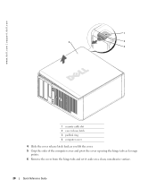
www.dell.com | support.dell.com 1 2 1 3 4 2 3 1 security cable slot 2 cover release latch 3 padlock ring 4 computer cover 4 Slide the cover release latch back as you lift the cover. 5 Grip the sides of the computer cover and pivot the cover up using the hinge tabs as leverage points. 6 Remove the cover from the hinge tabs and set it aside on a clean, nonabrasive surface. 20 Quick Reference Guide
www.dell.com | support.dell.com 1 2 1 3 4 2 3 1 security cable slot 2 cover release latch 3 padlock ring 4 computer cover 4 Slide the cover release latch back as you lift the cover. 5 Grip the sides of the computer cover and pivot the cover up using the hinge tabs as leverage points. 6 Remove the cover from the hinge tabs and set it aside on a clean, nonabrasive surface. 20 Quick Reference Guide
Quick Reference Guide
Page 21
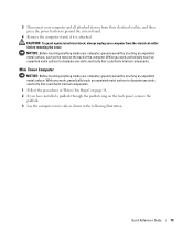
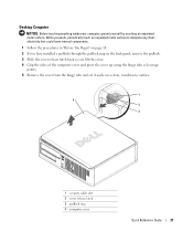
While you work, periodically touch an unpainted metal surface to dissipate any static electricity that could harm internal components. 1 Follow the procedures in "Before You Begin" on page 18. 2 If you have installed a padlock through the padlock ring on the back panel, remove the padlock. 3 Slide the cover release latch back as you lift the cover. 4 Grip the sides of the computer cover and pivot the cover up using the hinge tabs as leverage points. 5 Remove the cover from the hinge tabs and set it aside on a clean, nonabrasive surface. 1 4 2 3 1 security cable slot 2 cover release latch 3 ...
While you work, periodically touch an unpainted metal surface to dissipate any static electricity that could harm internal components. 1 Follow the procedures in "Before You Begin" on page 18. 2 If you have installed a padlock through the padlock ring on the back panel, remove the padlock. 3 Slide the cover release latch back as you lift the cover. 4 Grip the sides of the computer cover and pivot the cover up using the hinge tabs as leverage points. 5 Remove the cover from the hinge tabs and set it aside on a clean, nonabrasive surface. 1 4 2 3 1 security cable slot 2 cover release latch 3 ...
Quick Reference Guide
Page 22
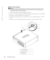
... hinge tabs and set it aside on a clean, nonabrasive surface. 1 4 2 3 22 Quick Reference Guide 1 security cable slot 2 cover release latch 3 padlock ring 4 computer cover www.dell.com | support.dell.com Small Form Factor Computer NOTICE: Before touching anything inside your computer, ground yourself by touching an unpainted metal surface.
... hinge tabs and set it aside on a clean, nonabrasive surface. 1 4 2 3 22 Quick Reference Guide 1 security cable slot 2 cover release latch 3 padlock ring 4 computer cover www.dell.com | support.dell.com Small Form Factor Computer NOTICE: Before touching anything inside your computer, ground yourself by touching an unpainted metal surface.
Quick Reference Guide
Page 24
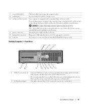
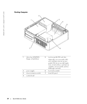
www.dell.com | support.dell.com Desktop Computer 2 1 3 4 5 7 6 1 drives bay (CD/DVD, floppy, or hard drive) 2 power supply 3 chassis intrusion switch 4 system board 5 two low-profile PCI card slots Optionally, you can install a PCI riser card that converts one low-profile and two full-height card slots. 6 heat sink assembly 7 front I/O panel 24 Quick Reference Guide A total of three card slots are available: one lowprofile PCI slot to two full-height slots.
www.dell.com | support.dell.com Desktop Computer 2 1 3 4 5 7 6 1 drives bay (CD/DVD, floppy, or hard drive) 2 power supply 3 chassis intrusion switch 4 system board 5 two low-profile PCI card slots Optionally, you can install a PCI riser card that converts one low-profile and two full-height card slots. 6 heat sink assembly 7 front I/O panel 24 Quick Reference Guide A total of three card slots are available: one lowprofile PCI slot to two full-height slots.
Quick Reference Guide
Page 25
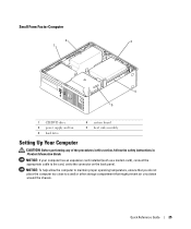
Quick Reference Guide 25 NOTICE: To help allow the computer to maintain proper operating temperature, ensure that you do not place the computer too close to the connector on the back panel. NOTICE: If your computer has an expansion card installed (such as a modem card), connect the appropriate cable to the card, not to a wall or other storage compartment that might prevent air circulation around the chassis. Small Form Factor Computer 2 3 1 4 5 1 CD/DVD drive 2 power supply and fan 3 hard drive 4 system board 5 heat sink assembly Setting Up Your Computer CAUTION: Before ...
Quick Reference Guide 25 NOTICE: To help allow the computer to maintain proper operating temperature, ensure that you do not place the computer too close to the connector on the back panel. NOTICE: If your computer has an expansion card installed (such as a modem card), connect the appropriate cable to the card, not to a wall or other storage compartment that might prevent air circulation around the chassis. Small Form Factor Computer 2 3 1 4 5 1 CD/DVD drive 2 power supply and fan 3 hard drive 4 system board 5 heat sink assembly Setting Up Your Computer CAUTION: Before ...
