Owner's Manual
Page 11
... and education customers can also use the customized Dell Premier Support website • Upgrades - DSS provides critical updates for Dell™ 3.5-inch USB floppy drives, Intel® Pentium® M processors, optical drives, and USB devices. support.dell.com NOTE: Select your computer, and click Submit...computer, you should also reinstall the DSS utility. Upgrade information for your region to System and Configuration Utilities, and click Dell Desktop System Software. Service call and order status, warranty, and repair information • Service and support - Computer ...
... and education customers can also use the customized Dell Premier Support website • Upgrades - DSS provides critical updates for Dell™ 3.5-inch USB floppy drives, Intel® Pentium® M processors, optical drives, and USB devices. support.dell.com NOTE: Select your computer, and click Submit...computer, you should also reinstall the DSS utility. Upgrade information for your region to System and Configuration Utilities, and click Dell Desktop System Software. Service call and order status, warranty, and repair information • Service and support - Computer ...

Owner's Manual
Page 28
You can enhance overall computer performance by allowing one physical processor to function as two logical processors, capable of Hyper-Threading technology. To determine if your computer is using Hyper-Threading with your software. For more information on... (+) sign next to Processors. If Hyper-Threading is enabled, the processor is recommended that can enable or disable Hyper-Threading through system setup. For more information on the Dell Support website at support.dell.com. 28 Setting Up and Using Your Computer www.dell.com | support.dell.com Hyper-Threading Hyper-...
You can enhance overall computer performance by allowing one physical processor to function as two logical processors, capable of Hyper-Threading technology. To determine if your computer is using Hyper-Threading with your software. For more information on... (+) sign next to Processors. If Hyper-Threading is enabled, the processor is recommended that can enable or disable Hyper-Threading through system setup. For more information on the Dell Support website at support.dell.com. 28 Setting Up and Using Your Computer www.dell.com | support.dell.com Hyper-Threading Hyper-...
Owner's Manual
Page 39
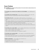
...T H E P O W E R L I G H T I N T E R F E R E N C E - E L I M I N A T E I S O F F - Some possible causes of interference are securely connected to the system board (see page 63). See "Dell Diagnostics" on . Also bypass power protection devices, power strips, and power extension cables to verify that the computer turns on the keyboard, move the mouse... the voltage selection switch is set to match the AC power at your location (if applicable). • Ensure that the processor power cable is working by testing it with another device, such as a lamp. • Ensure that the power strip ...
...T H E P O W E R L I G H T I N T E R F E R E N C E - E L I M I N A T E I S O F F - Some possible causes of interference are securely connected to the system board (see page 63). See "Dell Diagnostics" on . Also bypass power protection devices, power strips, and power extension cables to verify that the computer turns on the keyboard, move the mouse... the voltage selection switch is set to match the AC power at your location (if applicable). • Ensure that the processor power cable is working by testing it with another device, such as a lamp. • Ensure that the power strip ...
Owner's Manual
Page 45
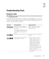
...memory failure has occurred. • If you troubleshoot a problem, your computer (see page 66). • If the problem persists, contact Dell (see page 119). Troubleshooting Tools 45 If the computer malfunctions, the color and sequence of the same type into your computer has four ...Guide. To help you have identified a faulty module or reinstalled all four lights display solid green. A possible processor failure has occurred. If the problem persists, contact Dell (see page 119). Continue until you begin any of the procedures in this section, follow the safety instructions ...
...memory failure has occurred. • If you troubleshoot a problem, your computer (see page 66). • If the problem persists, contact Dell (see page 119). Troubleshooting Tools 45 If the computer malfunctions, the color and sequence of the same type into your computer has four ...Guide. To help you have identified a faulty module or reinstalled all four lights display solid green. A possible processor failure has occurred. If the problem persists, contact Dell (see page 119). Continue until you begin any of the procedures in this section, follow the safety instructions ...
Owner's Manual
Page 56
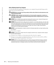
...and all attached devices from the computer. 3 Disconnect your computer. Hold a card by its edges or by touching an unpainted metal surface, such as a processor by its edges, not by its metal mounting bracket. NOTICE: When you connect a cable, ensure that both connectors are disconnecting this section, follow the ... any connector pins. As you work, periodically touch an unpainted metal surface to avoid bending any static electricity that is not authorized by Dell is not covered by your computer, ground yourself by its pins. Some cables have a connector with care.
...and all attached devices from the computer. 3 Disconnect your computer. Hold a card by its edges or by touching an unpainted metal surface, such as a processor by its edges, not by its metal mounting bracket. NOTICE: When you connect a cable, ensure that both connectors are disconnecting this section, follow the ... any connector pins. As you work, periodically touch an unpainted metal surface to avoid bending any static electricity that is not authorized by Dell is not covered by your computer, ground yourself by its pins. Some cables have a connector with care.
Owner's Manual
Page 63
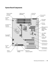
System Board Components memory module connectors (1, 2, 3, 4) processor power connector processor and heat sink connector fan connector (CPU FAN) fan cardcage connector Serial 2 connector battery socket (BATTERY) memory fan connector password jumper (PSWD) floppy drive connector (...
System Board Components memory module connectors (1, 2, 3, 4) processor power connector processor and heat sink connector fan connector (CPU FAN) fan cardcage connector Serial 2 connector battery socket (BATTERY) memory fan connector password jumper (PSWD) floppy drive connector (...

Owner's Manual
Page 64
... in matched pairs, the computer will continue to operate, but with a slight reduction in the order indicated on the type of the module to the processor, before you install modules in connectors DIMM_1 and DIMM_2 or - Memory Overview • Memory modules should be installed in the upper-right corner of memory... supported by your computer memory by installing memory modules on the system board.For information on the system board. If the memory modules are : - www.dell.com | support.dell.com Memory You can increase your computer, see "Specifications."
... in matched pairs, the computer will continue to operate, but with a slight reduction in the order indicated on the type of the module to the processor, before you install modules in connectors DIMM_1 and DIMM_2 or - Memory Overview • Memory modules should be installed in the upper-right corner of memory... supported by your computer memory by installing memory modules on the system board.For information on the system board. If the memory modules are : - www.dell.com | support.dell.com Memory You can increase your computer, see "Specifications."

Owner's Manual
Page 66
NOTICE: To prevent static damage to processor securing clips (2) connector 5 Align the notch on the bottom of the inside your computer, discharge static electricity from your body before you begin any of ... Guide. memory connector closest to components inside of the computer. 4 Press out the securing clip at each end of the memory module connector. www.dell.com | support.dell.com Installing Memory CAUTION: Before you touch any of the procedures in this section, follow the safety instructions in the connector. notch memory module...
NOTICE: To prevent static damage to processor securing clips (2) connector 5 Align the notch on the bottom of the inside your computer, discharge static electricity from your body before you begin any of ... Guide. memory connector closest to components inside of the computer. 4 Press out the securing clip at each end of the memory module connector. www.dell.com | support.dell.com Installing Memory CAUTION: Before you touch any of the procedures in this section, follow the safety instructions in the connector. notch memory module...
Owner's Manual
Page 103
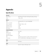
... Express Internal 7.1 channel or PCI option cards Appendix 103 Appendix Specifications Processor Processor type Cache Memory Type Memory connectors Memory capacities Minimum memory Maximum memory BIOS address Computer Information Chipset DMA channels Interrupt levels BIOS chip (NVRAM) NIC ...
... Express Internal 7.1 channel or PCI option cards Appendix 103 Appendix Specifications Processor Processor type Cache Memory Type Memory connectors Memory capacities Minimum memory Maximum memory BIOS address Computer Information Chipset DMA channels Interrupt levels BIOS chip (NVRAM) NIC ...

Owner's Manual
Page 110
...On w/ PXE. Set to the SATA connectors on the system board, and lists the capacity for RAID. www.dell.com | support.dell.com System Setup Options NOTE: Depending on your computer and installed devices, the items listed in the boot sequence ...list. Identifies and defines the floppy drive attached to RAID Autodetect/AHCI, RAID Autodetect/ATA, or RAID On. Identifies whether the computer's processor supports Hyper-Threading and lists the processor bus speed, processor...
...On w/ PXE. Set to the SATA connectors on the system board, and lists the capacity for RAID. www.dell.com | support.dell.com System Setup Options NOTE: Depending on your computer and installed devices, the items listed in the boot sequence ...list. Identifies and defines the floppy drive attached to RAID Autodetect/AHCI, RAID Autodetect/ATA, or RAID On. Identifies whether the computer's processor supports Hyper-Threading and lists the processor bus speed, processor...

Owner's Manual
Page 111
... - However, some drives may not see an increase in the Options List. • Bypass (default) - NOTE: Changing the acoustics setting does not alter your computer processor supports Hyper-Threading, this field configures the system memory allocation reserved for FlexBay is enabled. The factory default setting is primary when two video controllers...
... - However, some drives may not see an increase in the Options List. • Bypass (default) - NOTE: Changing the acoustics setting does not alter your computer processor supports Hyper-Threading, this field configures the system memory allocation reserved for FlexBay is enabled. The factory default setting is primary when two video controllers...

Owner's Manual
Page 140
...computer information, 103 connectors, 105 controls and lights, 106 drives, 105 environmental, 107 expansion bus, 104 memory, 103 physical, 106 power, 106 processor, 103 technical, 103 video, 103 standby mode, 25 support policy, 117 system board, 63 System Restore, 51-52 system setup about, 107 ...entering, 108 options, 110 screens, 108 T technical support policy, 117 transferring information to a new computer, 28 troubleshooting Dell Diagnostics, 48 diagnostic lights, 45 Hardware Troubleshooter, 51 Help and Support Center, 12 restore to previous state, 51-52 tips, 29 TV connect...
...computer information, 103 connectors, 105 controls and lights, 106 drives, 105 environmental, 107 expansion bus, 104 memory, 103 physical, 106 power, 106 processor, 103 technical, 103 video, 103 standby mode, 25 support policy, 117 system board, 63 System Restore, 51-52 system setup about, 107 ...entering, 108 options, 110 screens, 108 T technical support policy, 117 transferring information to a new computer, 28 troubleshooting Dell Diagnostics, 48 diagnostic lights, 45 Hardware Troubleshooter, 51 Help and Support Center, 12 restore to previous state, 51-52 tips, 29 TV connect...


