Owner's Manual
Page 5
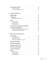
... 42 If the screen is blank 42 If the screen is difficult to read 43 3 Troubleshooting Tools Diagnostic Lights 45 Dell Diagnostics 48 Dell Diagnostics Main Menu 48 Drivers 49 What Is a Driver 49 Identifying Drivers 50 Reinstalling Drivers 50 Resolving Software and Hardware Incompatibilities... 51 Restoring Your Operating System 51 Using Microsoft Windows XP System Restore 52 Using Dell PC Restore by Symantec 53 4 Removing and Installing Parts Before You Begin 55 Recommended Tools 55 Turn Off Your Computer 55 Before Working Inside Your Computer ...
... 42 If the screen is blank 42 If the screen is difficult to read 43 3 Troubleshooting Tools Diagnostic Lights 45 Dell Diagnostics 48 Dell Diagnostics Main Menu 48 Drivers 49 What Is a Driver 49 Identifying Drivers 50 Reinstalling Drivers 50 Resolving Software and Hardware Incompatibilities... 51 Restoring Your Operating System 51 Using Microsoft Windows XP System Restore 52 Using Dell PC Restore by Symantec 53 4 Removing and Installing Parts Before You Begin 55 Recommended Tools 55 Turn Off Your Computer 55 Before Working Inside Your Computer ...
Owner's Manual
Page 29
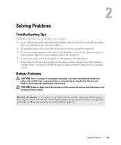
...restore your previous SATA operation settings and retry booting into your computer: • If you added or removed a part before the problem started, review the installation procedures and ensure that the device is incorrectly installed. Battery Problems CAUTION: There ...P L A C E T H E B A T T E R Y - If the battery still does not work , ensure that the part is correctly installed. • If a peripheral device does not work properly, contact Dell (see page 101). Solving Problems 29 Discard used batteries according to repeatedly reset time and date information after turning...
...restore your previous SATA operation settings and retry booting into your computer: • If you added or removed a part before the problem started, review the installation procedures and ensure that the device is incorrectly installed. Battery Problems CAUTION: There ...P L A C E T H E B A T T E R Y - If the battery still does not work , ensure that the part is correctly installed. • If a peripheral device does not work properly, contact Dell (see page 101). Solving Problems 29 Discard used batteries according to repeatedly reset time and date information after turning...
Owner's Manual
Page 48
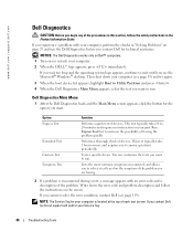
... follow the safety instructions in "Solving Problems" on page 29 and run the Dell Diagnostics before you want . Tests a specific device. Dell Diagnostics Main Menu 1 After the Dell Diagnostics loads and the Main Menu screen appears, click the button for your part. If you want to select a test based on the symptom of the...
... follow the safety instructions in "Solving Problems" on page 29 and run the Dell Diagnostics before you want . Tests a specific device. Dell Diagnostics Main Menu 1 After the Dell Diagnostics loads and the Main Menu screen appears, click the button for your part. If you want to select a test based on the symptom of the...

Owner's Manual
Page 55
... off your computer. 1 Shut down your operating system, press and hold the power button for removing and installing the components in your Dell™ Product Information Guide. • A component can be replaced by performing the removal procedure in this document may require the following ...data, save and close any open files and exit any open files, exit any attached devices are turned off . Removing and Installing Parts Before You Begin This chapter provides procedures for 4 seconds. Recommended Tools The procedures in reverse order. Unless otherwise noted, each procedure ...
... off your computer. 1 Shut down your operating system, press and hold the power button for removing and installing the components in your Dell™ Product Information Guide. • A component can be replaced by performing the removal procedure in this document may require the following ...data, save and close any open files and exit any open files, exit any attached devices are turned off . Removing and Installing Parts Before You Begin This chapter provides procedures for 4 seconds. Recommended Tools The procedures in reverse order. Unless otherwise noted, each procedure ...
Owner's Manual
Page 56
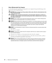
... computer from their electrical outlets, and then press the power button to servicing that could harm internal components. 56 Removing and Installing Parts While you work, periodically touch an unpainted metal surface to avoid bending any connector pins. Do not touch the components or contacts ... a cable, pull on its connector or on its pins. NOTICE: Only a certified service technician should perform repairs on a card. www.dell.com | support.dell.com Before Working Inside Your Computer Use the following steps before you begin any of the procedures in this type of the computer.
... computer from their electrical outlets, and then press the power button to servicing that could harm internal components. 56 Removing and Installing Parts While you work, periodically touch an unpainted metal surface to avoid bending any connector pins. Do not touch the components or contacts ... a cable, pull on its connector or on its pins. NOTICE: Only a certified service technician should perform repairs on a card. www.dell.com | support.dell.com Before Working Inside Your Computer Use the following steps before you begin any of the procedures in this type of the computer.
Owner's Manual
Page 57
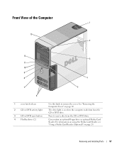
Press to remove the cover. See "Removing the Computer Cover" on page 20. The drive light is on when the computer reads data from the CD or DVD drive. Can contain an optional floppy drive or optional Media Card Reader. For information on using the Media Card Reader, see "Using a Media Card Reader (Optional)" on page 60. Removing and Installing Parts 57 Front View of the Computer 1 13 2 12 3 11 10 9 8 4 7 5 6 1 cover latch release 2 CD or DVD activity light 3 CD or DVD eject button 4 FlexBay drives (2) Use this latch to eject a disc from the CD or DVD drive.
Press to remove the cover. See "Removing the Computer Cover" on page 20. The drive light is on when the computer reads data from the CD or DVD drive. Can contain an optional floppy drive or optional Media Card Reader. For information on using the Media Card Reader, see "Using a Media Card Reader (Optional)" on page 60. Removing and Installing Parts 57 Front View of the Computer 1 13 2 12 3 11 10 9 8 4 7 5 6 1 cover latch release 2 CD or DVD activity light 3 CD or DVD eject button 4 FlexBay drives (2) Use this latch to eject a disc from the CD or DVD drive.
Owner's Manual
Page 58
... you troubleshoot a computer problem based on the diagnostic code. Used to help you access the Dell Support website or call technical support. 58 Removing and Installing Parts Use the headphone connector to attach a personal computer microphone for devices that there is adequately ventilated...front USB connectors for devices that the system is a minimum of two inches of space between all vents and any of speakers. www.dell.com | support.dell.com 5 IEEE 1394 connector (optional) 6 vents 7 USB 2.0 connectors (2) 8 power button 9 hard-drive activity light 10 diagnostic ...
... you troubleshoot a computer problem based on the diagnostic code. Used to help you access the Dell Support website or call technical support. 58 Removing and Installing Parts Use the headphone connector to attach a personal computer microphone for devices that there is adequately ventilated...front USB connectors for devices that the system is a minimum of two inches of space between all vents and any of speakers. www.dell.com | support.dell.com 5 IEEE 1394 connector (optional) 6 vents 7 USB 2.0 connectors (2) 8 power button 9 hard-drive activity light 10 diagnostic ...
Owner's Manual
Page 59
Removing and Installing Parts 59 Use the blue line-in connector - Use the pink microphone connector to attach multiple speakers. Use the yellow subwoofer connector to attach a personal computer ...
Removing and Installing Parts 59 Use the blue line-in connector - Use the pink microphone connector to attach multiple speakers. Use the yellow subwoofer connector to attach a personal computer ...

Owner's Manual
Page 60
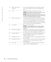
...On computers with the computer cover facing up. 4 Pull back the cover latch release on the top panel. 60 Removing and Installing Parts It is recommended that you use the front USB connectors for devices that sufficient space exists to support the removed cover-at the back... indicates that you must use the connector on which it from the electrical outlet before removing the cover. Access connectors for your network. www.dell.com | support.dell.com 3 network connector 4 USB 2.0 connectors (5) 5 card slots (6) To attach your computer to a network or broadband device, connect one end ...
...On computers with the computer cover facing up. 4 Pull back the cover latch release on the top panel. 60 Removing and Installing Parts It is recommended that you use the front USB connectors for devices that sufficient space exists to support the removed cover-at the back... indicates that you must use the connector on which it from the electrical outlet before removing the cover. Access connectors for your network. www.dell.com | support.dell.com 3 network connector 4 USB 2.0 connectors (5) 5 card slots (6) To attach your computer to a network or broadband device, connect one end ...

Owner's Manual
Page 61
Removing and Installing Parts 61 cover latch release computer cover back of computer hinge tabs (3) 5 Locate the three hinge tabs on the bottom edge of the computer. 6 Grip the sides of the computer cover and pivot the cover up. 7 Lift the cover away and set it aside in a secure location.
Removing and Installing Parts 61 cover latch release computer cover back of computer hinge tabs (3) 5 Locate the three hinge tabs on the bottom edge of the computer. 6 Grip the sides of the computer cover and pivot the cover up. 7 Lift the cover away and set it aside in a secure location.
Owner's Manual
Page 62
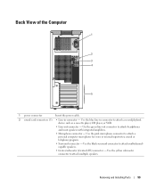
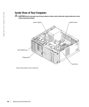
power supply system board CD or DVD drive *floppy drive *may not be present on all computers hard drive 62 Removing and Installing Parts www.dell.com | support.dell.com Inside View of Your Computer CAUTION: Before you begin any of the procedures in this section, follow the safety instructions in the Product Information Guide.
power supply system board CD or DVD drive *floppy drive *may not be present on all computers hard drive 62 Removing and Installing Parts www.dell.com | support.dell.com Inside View of Your Computer CAUTION: Before you begin any of the procedures in this section, follow the safety instructions in the Product Information Guide.
Owner's Manual
Page 63
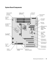
... (RTCRST) FlexBay USB connector PCI Express x1 card connector PCI Express x16 card connector PCI Express x4 card connector PCI card connectors Removing and Installing Parts 63
... (RTCRST) FlexBay USB connector PCI Express x1 card connector PCI Express x16 card connector PCI Express x4 card connector PCI card connectors Removing and Installing Parts 63

Owner's Manual
Page 64
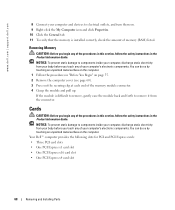
...connectors. • While installing memory modules, ensure that you install modules in the upper-right corner of matched memory size, speed, and technology. www.dell.com | support.dell.com Memory You can increase your computer memory by installing memory modules on the system board.For information on the system board. The recommended... in matched pairs, the computer will continue to the processor, before you do not mix ECC and non-ECC memory. 64 Removing and Installing Parts A pair of memory supported by your computer, see "Specifications." If the memory modules are : -
...connectors. • While installing memory modules, ensure that you install modules in the upper-right corner of matched memory size, speed, and technology. www.dell.com | support.dell.com Memory You can increase your computer memory by installing memory modules on the system board.For information on the system board. The recommended... in matched pairs, the computer will continue to the processor, before you do not mix ECC and non-ECC memory. 64 Removing and Installing Parts A pair of memory supported by your computer, see "Specifications." If the memory modules are : -

Owner's Manual
Page 65
... cannot be used by computer memory. You should install your original memory modules from the computer during a memory upgrade, keep them separate from Dell is less than 4 GB. If possible, do not pair an original memory module with a new memory module. however, the amount of ...may not start properly. Certain components within the computer require address space in connectors DIMM_1 and DIMM_2 or connectors DIMM_3 and DIMM_4. Removing and Installing Parts 65 NOTICE: If you use four 1-GB DIMMs. Current operating systems, such as Microsoft® Windows® XP, can only use a...
... cannot be used by computer memory. You should install your original memory modules from the computer during a memory upgrade, keep them separate from Dell is less than 4 GB. If possible, do not pair an original memory module with a new memory module. however, the amount of ...may not start properly. Certain components within the computer require address space in connectors DIMM_1 and DIMM_2 or connectors DIMM_3 and DIMM_4. Removing and Installing Parts 65 NOTICE: If you use four 1-GB DIMMs. Current operating systems, such as Microsoft® Windows® XP, can only use a...

Owner's Manual
Page 66
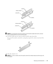
... computer. 4 Press out the securing clip at each end of the memory module connector. notch memory module cutouts (2) crossbar 66 Removing and Installing Parts www.dell.com | support.dell.com Installing Memory CAUTION: Before you begin any of your body before you touch any of the procedures in this section, follow the safety...
... computer. 4 Press out the securing clip at each end of the memory module connector. notch memory module cutouts (2) crossbar 66 Removing and Installing Parts www.dell.com | support.dell.com Installing Memory CAUTION: Before you begin any of your body before you touch any of the procedures in this section, follow the safety...
Owner's Manual
Page 67
... you insert the module correctly, the securing clips snap into the cutouts at each end of the module. 7 Close the computer cover. Removing and Installing Parts 67
... you insert the module correctly, the securing clips snap into the cutouts at each end of the module. 7 Close the computer cover. Removing and Installing Parts 67
Owner's Manual
Page 68
... electricity from your body before you begin any of the procedures in this section, follow the safety instructions in the Product Information Guide. Your Dell™ computer provides the following slots for PCI and PCI Express cards: • Three PCI card slots • One PCI Express x1 card... slot • One PCI Express x16 card slot • One PCI Express x4 card slot 68 Removing and Installing Parts www.dell.com | support.dell.com 8 Connect your computer and devices to remove it from the connector. You can do so by touching an unpainted metal surface ...
... electricity from your body before you begin any of the procedures in this section, follow the safety instructions in the Product Information Guide. Your Dell™ computer provides the following slots for PCI and PCI Express cards: • Three PCI card slots • One PCI Express x1 card... slot • One PCI Express x16 card slot • One PCI Express x4 card slot 68 Removing and Installing Parts www.dell.com | support.dell.com 8 Connect your computer and devices to remove it from the connector. You can do so by touching an unpainted metal surface ...

Owner's Manual
Page 69
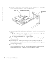
...computer cover (see ""Removing a PCI Card" on page 72". release tabs (2) card retention door alignment bar alignment guide filler bracket Removing and Installing Parts 69 If you are replacing a card, remove the current driver for Audigy II and IEEE 1394 PCI add-in-cards that includes a front-mounted ...IEEE 1394 connector. 1 Follow the procedures in the next section. Installing a PCI Card NOTE: Dell offers an optional customer kit for the card from the operating system. PCI Cards If you are removing but not replacing a card, see page...
...computer cover (see ""Removing a PCI Card" on page 72". release tabs (2) card retention door alignment bar alignment guide filler bracket Removing and Installing Parts 69 If you are replacing a card, remove the current driver for Audigy II and IEEE 1394 PCI add-in-cards that includes a front-mounted ...IEEE 1394 connector. 1 Follow the procedures in the next section. Installing a PCI Card NOTE: Dell offers an optional customer kit for the card from the operating system. PCI Cards If you are removing but not replacing a card, see page...
Owner's Manual
Page 70
... it out of its top corners, and ease it in the open . b Set the retention mechanism aside in the computer, remove the card. www.dell.com | support.dell.com 3 Push the two release tabs on configuring the card, making internal connections, or otherwise customizing it will remain in place. release tab card...
... it out of its top corners, and ease it in the open . b Set the retention mechanism aside in the computer, remove the card. www.dell.com | support.dell.com 3 Push the two release tabs on configuring the card, making internal connections, or otherwise customizing it will remain in place. release tab card...
Owner's Manual
Page 71
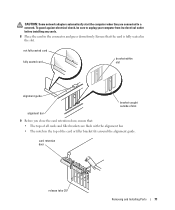
To guard against electrical shock, be sure to a network. card retention door release tabs (2) Removing and Installing Parts 71 CAUTION: Some network adapters automatically start the computer when they are flush with the alignment bar. • The notch in the top of the ...
To guard against electrical shock, be sure to a network. card retention door release tabs (2) Removing and Installing Parts 71 CAUTION: Some network adapters automatically start the computer when they are flush with the alignment bar. • The notch in the top of the ...

