Reference Guide
Page 7
... maintenance to protect the computer. • Chapter 2, "Installing Upgrades on the System Board," provides information on performing various upgrades, such as expansion cards, memory, and drives. • Chapter 6, "Getting Help," provides information on obtaining technical assis- Preface About This Guide This guide is supplemental reference material. • Appendix B, "System Setup Program," describes the system setup program used by both first-time and experienced computer users...
... maintenance to protect the computer. • Chapter 2, "Installing Upgrades on the System Board," provides information on performing various upgrades, such as expansion cards, memory, and drives. • Chapter 6, "Getting Help," provides information on obtaining technical assis- Preface About This Guide This guide is supplemental reference material. • Appendix B, "System Setup Program," describes the system setup program used by both first-time and experienced computer users...

Reference Guide
Page 18
... operating system, the two highperformance Universal Serial Bus (USB) ports provide a single connection point for connecting external devices. • A Personal System/2 (PS/2)-style keyboard port and a PS/2-compatible mouse port. cation 1.0A. • For systems running . NOTE: If you attach a USB device that support Advanced Technology Attachment (ATA)-33/66 Ultra direct memory access (DMA) hard-disk drives and optical drives, such as CD-ROM drives. The system board includes the following software is included with your Dell...
... operating system, the two highperformance Universal Serial Bus (USB) ports provide a single connection point for connecting external devices. • A Personal System/2 (PS/2)-style keyboard port and a PS/2-compatible mouse port. cation 1.0A. • For systems running . NOTE: If you attach a USB device that support Advanced Technology Attachment (ATA)-33/66 Ultra direct memory access (DMA) hard-disk drives and optical drives, such as CD-ROM drives. The system board includes the following software is included with your Dell...

Reference Guide
Page 19
... information). See "Adding Memory" in Chapter 3). • The system setup program for viewing and changing system configuration infor- support.dell.com Introduction 1-3 mation (see "Running the Dell Diagnostics" in Chapter 2 before purchasing such an upgrade. Purchasing memory upgrades from Dell Spare Parts ensures system compatibility; Available Upgrades The upgrades Dell offers undergo rigorous testing to ensure proper operation with your system's memory up to 512 MB by installing additional 168-pin, 100-megahertz...
... information). See "Adding Memory" in Chapter 3). • The system setup program for viewing and changing system configuration infor- support.dell.com Introduction 1-3 mation (see "Running the Dell Diagnostics" in Chapter 2 before purchasing such an upgrade. Purchasing memory upgrades from Dell Spare Parts ensures system compatibility; Available Upgrades The upgrades Dell offers undergo rigorous testing to ensure proper operation with your system's memory up to 512 MB by installing additional 168-pin, 100-megahertz...
Reference Guide
Page 32
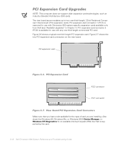
... PCI card. Also check the Windows 98, Windows Me, or Windows 2000 Device Manager, or Windows NT Diagnostics for an available interrupt request (IRQ) line that you have a slot available for use with Dimension 900 system-specific expansion cards available only from Dell (see "Available Upgrades" in Chapter 1). PCI expansion-card connector 2 (PCI2) is supported by the card. 2-12 Dell Dimension 900 System Reference and Troubleshooting Guide PCI expansion-card connector 1 (PCI1) is reserved for the type of card you are installing. PCI expansion card...
... PCI card. Also check the Windows 98, Windows Me, or Windows 2000 Device Manager, or Windows NT Diagnostics for an available interrupt request (IRQ) line that you have a slot available for use with Dimension 900 system-specific expansion cards available only from Dell (see "Available Upgrades" in Chapter 1). PCI expansion-card connector 2 (PCI2) is supported by the card. 2-12 Dell Dimension 900 System Reference and Troubleshooting Guide PCI expansion-card connector 1 (PCI1) is reserved for the type of card you are installing. PCI expansion card...

Reference Guide
Page 33
... "Removing and Replacing the Riser-Board Bracket" found earlier in the Microsoft Windows 98 or Windows Me operating system, perform the following steps: 1. Installing Expansion Cards 1. NOTE: The PCI1 connector (see Figure 2-7) is available for installation as instructed in the documentation that came with Dimension 900 system-specific expansion cards available only from Dell (see "Available Upgrades" in your card is configured to work with any one-third-length commercial PCI card...
... "Removing and Replacing the Riser-Board Bracket" found earlier in the Microsoft Windows 98 or Windows Me operating system, perform the following steps: 1. Installing Expansion Cards 1. NOTE: The PCI1 connector (see Figure 2-7) is available for installation as instructed in the documentation that came with Dimension 900 system-specific expansion cards available only from Dell (see "Available Upgrades" in your card is configured to work with any one-third-length commercial PCI card...
Reference Guide
Page 36
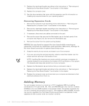
.... 2-16 Dell Dimension 900 System Reference and Troubleshooting Guide Adding Memory You can increase memory to the instructions in "Removing and Replacing the Riser-Board Bracket" found earlier in this chapter. 2. 11. If necessary, disconnect any required drivers for information on installing any cables connected to their electrical outlets and turn them on the system board. Replace the filler-bracket cap and screw that came with the expansion card for...
.... 2-16 Dell Dimension 900 System Reference and Troubleshooting Guide Adding Memory You can increase memory to the instructions in "Removing and Replacing the Riser-Board Bracket" found earlier in this chapter. 2. 11. If necessary, disconnect any required drivers for information on installing any cables connected to their electrical outlets and turn them on the system board. Replace the filler-bracket cap and screw that came with the expansion card for...

Reference Guide
Page 38
Replace the expansion cards, riser-board bracket, and the computer cover, and reconnect your computer and devices to their electrical outlets and turn them on the System Information screen is correct. 2-18 Dell Dimension 900 System Reference and Troubleshooting Guide Remove the computer cover according to the instructions in "Removing and Replacing the Riser-Board Bracket" found earlier in this chapter. 3. NOTE: The system memory value reported by the operating system...
Replace the expansion cards, riser-board bracket, and the computer cover, and reconnect your computer and devices to their electrical outlets and turn them on the System Information screen is correct. 2-18 Dell Dimension 900 System Reference and Troubleshooting Guide Remove the computer cover according to the instructions in "Removing and Replacing the Riser-Board Bracket" found earlier in this chapter. 3. NOTE: The system memory value reported by the operating system...
Reference Guide
Page 39
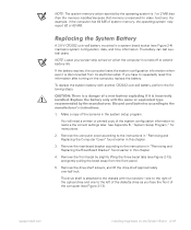
.... support.dell.com Installing Upgrades on when the computer is turned off to the instructions in "Removing and Replacing the Riser-Board Bracket" found earlier in this information after turning on the computer, replace the battery. The battery can last several years. If you face the front of a new battery exploding if it is disconnected from the front panel. 5. See Appendix B, "System Setup Program," for video functions. The drive...
.... support.dell.com Installing Upgrades on when the computer is turned off to the instructions in "Removing and Replacing the Riser-Board Bracket" found earlier in this information after turning on the computer, replace the battery. The battery can last several years. If you face the front of a new battery exploding if it is disconnected from the front panel. 5. See Appendix B, "System Setup Program," for video functions. The drive...
Reference Guide
Page 50
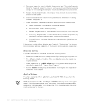
... settings on obtaining technical assistance. Remove all drives. 3-8 Dell Dimension 900 System Reference and Troubleshooting Guide Replace the patch cable or network cable from causing an interrupt or input/output (I/O) port resource conflict. 5. Such vibration and associated noise do not indicate a defect in this chapter. d. Check the network card connector for information on the Disk Drives option of the system setup program as described in Appendix B, "System Setup Program." • Run the Diskette device...
... settings on obtaining technical assistance. Remove all drives. 3-8 Dell Dimension 900 System Reference and Troubleshooting Guide Replace the patch cable or network cable from causing an interrupt or input/output (I/O) port resource conflict. 5. Such vibration and associated noise do not indicate a defect in this chapter. d. Check the network card connector for information on the Disk Drives option of the system setup program as described in Appendix B, "System Setup Program." • Run the Diskette device...

Reference Guide
Page 58
... updated drivers for products purchased from standby mode. Turns off the monitor, stops the hard-disk drive, and turns off the monitor so that the computer uses less power. NOTE: The system may cause errors or performance degradation. 4-2 Dell Dimension 900 System Reference and Troubleshooting Guide Device problems can press any key to turn on the Windows 2000 and Windows Me taskbar. For Windows 2000 and Windows Me, the following additional tabs are included in the Power Options...
... updated drivers for products purchased from standby mode. Turns off the monitor, stops the hard-disk drive, and turns off the monitor so that the computer uses less power. NOTE: The system may cause errors or performance degradation. 4-2 Dell Dimension 900 System Reference and Troubleshooting Guide Device problems can press any key to turn on the Windows 2000 and Windows Me taskbar. For Windows 2000 and Windows Me, the following additional tabs are included in the Power Options...

Reference Guide
Page 69
.... 2. Replace the riser-board bracket. Click the Start button, point to verify that are multiple entries for some specific types of expansion cards. e. support.dell.com The following steps: 1. Resolve any of the system configuration, remove them from the list. Verify the modem configuration as described in "Removing and Replacing the Riser-Board Bracket" in Chapter 2. 5. f. Click More Info to Settings, and click Control Panel. If there are not part...
.... 2. Replace the riser-board bracket. Click the Start button, point to verify that are multiple entries for some specific types of expansion cards. e. support.dell.com The following steps: 1. Resolve any of the system configuration, remove them from the list. Verify the modem configuration as described in "Removing and Replacing the Riser-Board Bracket" in Chapter 2. 5. f. Click More Info to Settings, and click Control Panel. If there are not part...

Reference Guide
Page 70
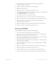
...," for instructions on obtaining technical assistance. 2. Clear nonvolatile random-access memory (NVRAM) as described in "Removing and Replacing the Riser-Board Bracket" in Appendix B. 8. Check the network card connector for information about their service. NOTE: If you can connect to the network but are having problems accessing network resources, contact your Internet service provider (ISP) for physical damage. To troubleshoot a network card, perform the following problems: • Wrong or incorrectly installed network interface controller (NIC) drivers •...
...," for instructions on obtaining technical assistance. 2. Clear nonvolatile random-access memory (NVRAM) as described in "Removing and Replacing the Riser-Board Bracket" in Appendix B. 8. Check the network card connector for information about their service. NOTE: If you can connect to the network but are having problems accessing network resources, contact your Internet service provider (ISP) for physical damage. To troubleshoot a network card, perform the following problems: • Wrong or incorrectly installed network interface controller (NIC) drivers •...

Reference Guide
Page 71
... good location on obtaining technical assistance. If the network card is 1 or 2 MB less than the memory installed because that the right drivers are being used. 9. Turn on the System Information screen. Reseating DIMMs 1. Remove the expansion cards as described in Chapter 2. 4. support.dell.com Checking Inside Your Computer 5-5 c. System Memory If a random-access memory (RAM) error message appears, troubleshoot the memory by the operating system is still not detected, see Appendix C, "Beep Codes and...
... good location on obtaining technical assistance. If the network card is 1 or 2 MB less than the memory installed because that the right drivers are being used. 9. Turn on the System Information screen. Reseating DIMMs 1. Remove the expansion cards as described in Chapter 2. 4. support.dell.com Checking Inside Your Computer 5-5 c. System Memory If a random-access memory (RAM) error message appears, troubleshoot the memory by the operating system is still not detected, see Appendix C, "Beep Codes and...

Reference Guide
Page 87
... board. Entering the System Setup Program Enter the system setup program as enable and disable your system. 2. You can use to load into memory, let the system complete the load operation. Then shut down the information for example, the user password Dell recommends that identify the incorrect configuration settings. Each time you turn on or restart your computer, the system compares the installed hardware to the hardware listed in the configuration...
... board. Entering the System Setup Program Enter the system setup program as enable and disable your system. 2. You can use to load into memory, let the system complete the load operation. Then shut down the information for example, the user password Dell recommends that identify the incorrect configuration settings. Each time you turn on or restart your computer, the system compares the installed hardware to the hardware listed in the configuration...

Reference Guide
Page 104
... . Remove the computer cover according to resume. Reset Resource Assignments Set to No (default) to handle all expansion cards according to the instructions in "Removing Expansion Cards" found in Chapter 2. Restore On AC/ Power Loss Determines the system mode of operation after an AC power failure. To disable a forgotten password, perform the following additional options: Resume Day Sets the day for the RTC alarm function to the instructions in "Removing and Replacing...
... . Remove the computer cover according to resume. Reset Resource Assignments Set to No (default) to handle all expansion cards according to the instructions in "Removing Expansion Cards" found in Chapter 2. Restore On AC/ Power Loss Determines the system mode of operation after an AC power failure. To disable a forgotten password, perform the following additional options: Resume Day Sets the day for the RTC alarm function to the instructions in "Removing and Replacing...
Reference Guide
Page 105
.... 2. Move the password jumper (JP6) to the instructions in "Removing and Replacing the Computer Cover" found in Chapter 2. 14. Replace all devices, perform the following steps: 1. Clearing NVRAM To clear NVRAM for all expansion cards, the riser-board bracket, and the computer cover. 15. Remove the computer cover according to the "enabled" setting described in "Password Jumper" in Chapter 2. 3. Remove all expansion cards according to the electrical outlet and turn it on...
.... 2. Move the password jumper (JP6) to the instructions in "Removing and Replacing the Computer Cover" found in Chapter 2. 14. Replace all devices, perform the following steps: 1. Clearing NVRAM To clear NVRAM for all expansion cards, the riser-board bracket, and the computer cover. 15. Remove the computer cover according to the "enabled" setting described in "Password Jumper" in Chapter 2. 3. Remove all expansion cards according to the electrical outlet and turn it on...

Reference Guide
Page 109
..., turn off the computer and disconnect your hard-disk drive does not have a bootable operating system installed on it. IDE Drive n Error IDE Drive n Auto Detection Failed The IDE drive may be malfunctioning. I/O Parity Error The I /O expansion ROM fails to reboot The diskette in Chapter 4. Run the IDE Devices tests as described in "Running the Dell Diagnostics" in Chapter 3. See "Resolving Software and Hardware Incompatibilities" in drive A or your system and devices from drive...
..., turn off the computer and disconnect your hard-disk drive does not have a bootable operating system installed on it. IDE Drive n Error IDE Drive n Auto Detection Failed The IDE drive may be malfunctioning. I/O Parity Error The I /O expansion ROM fails to reboot The diskette in Chapter 4. Run the IDE Devices tests as described in "Running the Dell Diagnostics" in Chapter 3. See "Resolving Software and Hardware Incompatibilities" in drive A or your system and devices from drive...

Reference Guide
Page 117
...assistance technical, 6-1 telephone numbers, 6-6 warranty repair or credit, 6-4 audio driver, 4-3 B battery location, 2-6 replacing, 2-19 beep codes, C-1 Boot Options screen, system setup program, B-11 Boot-block jumper settings, 2-10 C cache memory, A-1 calling Dell, 6-6 cautions, x chassis. See computer chip set update utility driver, 4-3 clearing NVRAM, B-19 computer technical specifications, A-1 connections troubleshooting, 3-2 connectors audio cable, 2-6 DC main power input, 2-6 DIMM socket, 2-6 diskette-drive interface, 2-6 hard-disk-drive activity indicator, 2-6 headphone, 2-6 keyboard...
...assistance technical, 6-1 telephone numbers, 6-6 warranty repair or credit, 6-4 audio driver, 4-3 B battery location, 2-6 replacing, 2-19 beep codes, C-1 Boot Options screen, system setup program, B-11 Boot-block jumper settings, 2-10 C cache memory, A-1 calling Dell, 6-6 cautions, x chassis. See computer chip set update utility driver, 4-3 clearing NVRAM, B-19 computer technical specifications, A-1 connections troubleshooting, 3-2 connectors audio cable, 2-6 DC main power input, 2-6 DIMM socket, 2-6 diskette-drive interface, 2-6 hard-disk-drive activity indicator, 2-6 headphone, 2-6 keyboard...

Reference Guide
Page 118
... set update utility, 4-3 installed on system board, 1-2 troubleshooting, 3-9 hardware options. See DIMMs E electrostatic discharge. See upgrade options help , 6-1 grounding procedure, 2-1 H hard-disk drives EIDE support on your system, 4-3 other, 4-3 reinstalling, 4-2 reinstalling from Dell Dimension ResourceCD, 4-3 security, 4-3 video, 4-3 drives bays, A-3 cables, 2-4 troubleshooting, 3-8 types supported, 1-2 dual in-line memory modules. D Date and Time screen, system setup program, B-13 DC power cables, 2-4 Dell Diagnostics, 3-9 Dell Dimension ResourceCD, 3-9, 4-2 diagnosing problems...
... set update utility, 4-3 installed on system board, 1-2 troubleshooting, 3-9 hardware options. See DIMMs E electrostatic discharge. See upgrade options help , 6-1 grounding procedure, 2-1 H hard-disk drives EIDE support on your system, 4-3 other, 4-3 reinstalling, 4-2 reinstalling from Dell Dimension ResourceCD, 4-3 security, 4-3 video, 4-3 drives bays, A-3 cables, 2-4 troubleshooting, 3-8 types supported, 1-2 dual in-line memory modules. D Date and Time screen, system setup program, B-13 DC power cables, 2-4 Dell Diagnostics, 3-9 Dell Dimension ResourceCD, 3-9, 4-2 diagnosing problems...

Reference Guide
Page 119
... cards PnP/PCI Options submenu, system setup program, B-17 POST beep codes, C-1 power sources troubleshooting, 3-2 support.dell.com Index 3 integrated drive electronics. See IDE interface cables about, 2-4 Internet help tools, 6-2 J jumpers about, 2-8 boot-block jumper settings, 2-10 NVRAM jumper settings, 2-9 password jumper settings, 2-8 processor mode jumper settings, 2-9 system board locations, 2-6 K keys and key combinations Dell Diagnostics, 3-13 system setup program, B-2 N nonvolatile random-access memory. See NVRAM notational conventions, x Notes, x Notices, x NVRAM clearing...
... cards PnP/PCI Options submenu, system setup program, B-17 POST beep codes, C-1 power sources troubleshooting, 3-2 support.dell.com Index 3 integrated drive electronics. See IDE interface cables about, 2-4 Internet help tools, 6-2 J jumpers about, 2-8 boot-block jumper settings, 2-10 NVRAM jumper settings, 2-9 password jumper settings, 2-8 processor mode jumper settings, 2-9 system board locations, 2-6 K keys and key combinations Dell Diagnostics, 3-13 system setup program, B-2 N nonvolatile random-access memory. See NVRAM notational conventions, x Notes, x Notices, x NVRAM clearing...


