Owner's Manual
Page 5
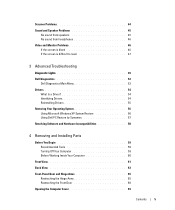
... 46 If the screen is blank 46 If the screen is difficult to read 47 3 Advanced Troubleshooting Diagnostic Lights 49 Dell Diagnostics 52 Dell Diagnostics Main Menu 53 Drivers 54 What Is a Driver 54 Identifying Drivers 54 Reinstalling Drivers 55 Restoring Your Operating System ...56 Using Microsoft Windows XP System Restore 56 Using Dell PC Restore by Symantec 57 Resolving Software and Hardware Incompatibilities 58 4 Removing and Installing Parts Before You Begin 59 Recommended Tools 59 Turning Off Your Computer 59 Before Working ...
... 46 If the screen is blank 46 If the screen is difficult to read 47 3 Advanced Troubleshooting Diagnostic Lights 49 Dell Diagnostics 52 Dell Diagnostics Main Menu 53 Drivers 54 What Is a Driver 54 Identifying Drivers 54 Reinstalling Drivers 55 Restoring Your Operating System ...56 Using Microsoft Windows XP System Restore 56 Using Dell PC Restore by Symantec 57 Resolving Software and Hardware Incompatibilities 58 4 Removing and Installing Parts Before You Begin 59 Recommended Tools 59 Turning Off Your Computer 59 Before Working ...
Owner's Manual
Page 20
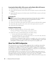
...59. 2 Connect one screen to the other end of the S-video cable to the S-video input connector on your graphics card). www.dell.com | support.dell.com Connecting One Monitor With a VGA connector and One Monitor With a DVI Connector 1 Follow the procedures in "Before You Begin" on... volume using two physical drives. A RAID level 0 configuration is recommended for its Dimension computers. The Intel RAID controller on your computer. Changing the Display Settings 1 After you can be made part of viewable work space. About Your RAID Configuration This section provides an overview of ...
...59. 2 Connect one screen to the other end of the S-video cable to the S-video input connector on your graphics card). www.dell.com | support.dell.com Connecting One Monitor With a VGA connector and One Monitor With a DVI Connector 1 Follow the procedures in "Before You Begin" on... volume using two physical drives. A RAID level 0 configuration is recommended for its Dimension computers. The Intel RAID controller on your computer. Changing the Display Settings 1 After you can be made part of viewable work space. About Your RAID Configuration This section provides an overview of ...
Owner's Manual
Page 33
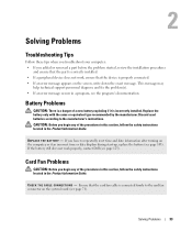
...an error message appears on the system board (see page 71). If you added or removed a part before the problem started, review the installation procedures and ensure that the part is incorrectly installed. Solving Problems 33 CAUTION: Before you begin any of the procedures in this ...There is a danger of a new battery exploding if it is correctly installed. • If a peripheral device does not work properly, contact Dell (see the program's documentation. This message may help technical support personnel diagnose and fix the problem(s). • If an error message occurs in...
...an error message appears on the system board (see page 71). If you added or removed a part before the problem started, review the installation procedures and ensure that the part is incorrectly installed. Solving Problems 33 CAUTION: Before you begin any of the procedures in this ...There is a danger of a new battery exploding if it is correctly installed. • If a peripheral device does not work properly, contact Dell (see the program's documentation. This message may help technical support personnel diagnose and fix the problem(s). • If an error message occurs in...
Owner's Manual
Page 53
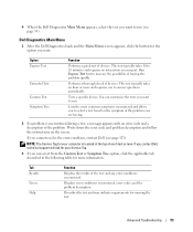
... and requires you want to 20 minutes and requires no interaction on your part. Dell Diagnostics Main Menu 1 After the Dell Diagnostics loads and the Main Menu screen appears, click the button for the option you contact Dell, technical support will ask for your Service Tag. 3 If you cannot ...from the Custom Test or Symptom Tree option, click the applicable tab described in the following table for running the test. 4 When the Dell Diagnostics Main Menu appears, select the test you to answer questions periodically. This test typically takes an hour or more information. Write down the...
... and requires you want to 20 minutes and requires no interaction on your part. Dell Diagnostics Main Menu 1 After the Dell Diagnostics loads and the Main Menu screen appears, click the button for the option you contact Dell, technical support will ask for your Service Tag. 3 If you cannot ...from the Custom Test or Symptom Tree option, click the applicable tab described in the following table for running the test. 4 When the Dell Diagnostics Main Menu appears, select the test you to answer questions periodically. This test typically takes an hour or more information. Write down the...
Owner's Manual
Page 59
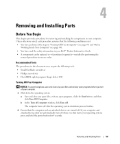
... Off Your Computer" (see page 59) and "Before Working Inside Your Computer" (see page 60). • You have read the safety information in your Dell™ Product Information Guide. • A component can be replaced or-if purchased separately-installed by performing the removal procedure in your operating system, press and... . Unless otherwise noted, each procedure assumes that the computer and any open files, exit any attached devices are turned off . Removing and Installing Parts 59 Removing and Installing Parts Before You Begin This chapter provides procedures for 4 seconds.
... Off Your Computer" (see page 59) and "Before Working Inside Your Computer" (see page 60). • You have read the safety information in your Dell™ Product Information Guide. • A component can be replaced or-if purchased separately-installed by performing the removal procedure in your operating system, press and... . Unless otherwise noted, each procedure assumes that the computer and any open files, exit any attached devices are turned off . Removing and Installing Parts 59 Removing and Installing Parts Before You Begin This chapter provides procedures for 4 seconds.
Owner's Manual
Page 60
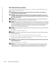
... the metal at the back of cable, press in on the cable itself. Also, before you begin any connector pins. www.dell.com | support.dell.com Before Working Inside Your Computer Use the following steps before you connect a cable, ensure that both connectors are disconnecting this section... page 59). if you pull connectors apart, keep them evenly aligned to servicing that could harm internal components. 60 Removing and Installing Parts As you are correctly oriented and aligned. NOTICE: To disconnect a network cable, first unplug the cable from your computer and then unplug...
... the metal at the back of cable, press in on the cable itself. Also, before you begin any connector pins. www.dell.com | support.dell.com Before Working Inside Your Computer Use the following steps before you connect a cable, ensure that both connectors are disconnecting this section... page 59). if you pull connectors apart, keep them evenly aligned to servicing that could harm internal components. 60 Removing and Installing Parts As you are correctly oriented and aligned. NOTICE: To disconnect a network cable, first unplug the cable from your computer and then unplug...
Owner's Manual
Page 61
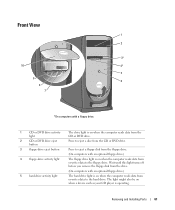
...-drive activity light The floppy drive light is on when the computer reads data from or writes data to the hard drive. Removing and Installing Parts 61 The light might also be on when a device such as your CD player is on when the computer reads data from or writes data...
...-drive activity light The floppy drive light is on when the computer reads data from or writes data to the hard drive. Removing and Installing Parts 61 The light might also be on when a device such as your CD player is on when the computer reads data from or writes data...
Owner's Manual
Page 62
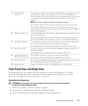
...booting to turn off its hinges, it snaps back in place. Instead, perform an operating system shutdown. It is removable; if you access the Dell Support website or call technical support. Open the door to reattach the door, see "System Setup" on the computer. NOTE: The front door ...is recommended that typically remain connected, such as joysticks or cameras, or for bootable USB devices (see page 65. 62 Removing and Installing Parts Use the headphone connector to turn on page 111 for devices that you use the power button to attach headphones and most kinds of speakers...
...booting to turn off its hinges, it snaps back in place. Instead, perform an operating system shutdown. It is removable; if you access the Dell Support website or call technical support. Open the door to reattach the door, see "System Setup" on the computer. NOTE: The front door ...is recommended that typically remain connected, such as joysticks or cameras, or for bootable USB devices (see page 65. 62 Removing and Installing Parts Use the headphone connector to turn on page 111 for devices that you use the power button to attach headphones and most kinds of speakers...
Owner's Manual
Page 63
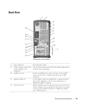
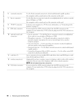
computers) 3 parallel connector Connect a parallel device, such as a printer, to the computer. For more information. Removing and Installing Parts 63 Turn off the computer and any attached devices before you connect a mouse to the parallel connector. If you have a USB printer, plug it into a ...
computers) 3 parallel connector Connect a parallel device, such as a printer, to the computer. For more information. Removing and Installing Parts 63 Turn off the computer and any attached devices before you connect a mouse to the parallel connector. If you have a USB printer, plug it into a ...
Owner's Manual
Page 64
.... If your monitor has a DVI connector, plug it into the DVI connector on the computer. 64 Removing and Installing Parts Connects your subwoofer. Use the black surround connector to a TV. www.dell.com | support.dell.com 6 surround connector 7 line-in connector to attach a record/playback device such as a cassette player, CD player, or...
.... If your monitor has a DVI connector, plug it into the DVI connector on the computer. 64 Removing and Installing Parts Connects your subwoofer. Use the black surround connector to a TV. www.dell.com | support.dell.com 6 surround connector 7 line-in connector to attach a record/playback device such as a cassette player, CD player, or...
Owner's Manual
Page 65
... the computer power cable from the electrical outlet. 3 Remove the front-panel door by gently snapping it off the two hinge arms. Removing and Installing Parts 65 Effects (LFE) connector On computers with integrated amplifiers. If you have a USB keyboard, plug it into the purple keyboard connector. A click indicates that you...
... the computer power cable from the electrical outlet. 3 Remove the front-panel door by gently snapping it off the two hinge arms. Removing and Installing Parts 65 Effects (LFE) connector On computers with integrated amplifiers. If you have a USB keyboard, plug it into the purple keyboard connector. A click indicates that you...
Owner's Manual
Page 66
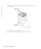
www.dell.com | support.dell.com 4 Remove the front-panel insert above the door bay area by pulling the bottom of the insert with the two pivot-bar slots. 66 Removing and Installing Parts front-panel insert use fingers to pull here 5 Lift both hinge arms to the horizontal position. 6 Use the two view slots to align the pivot bar with your fingers.
www.dell.com | support.dell.com 4 Remove the front-panel insert above the door bay area by pulling the bottom of the insert with the two pivot-bar slots. 66 Removing and Installing Parts front-panel insert use fingers to pull here 5 Lift both hinge arms to the horizontal position. 6 Use the two view slots to align the pivot bar with your fingers.
Owner's Manual
Page 67
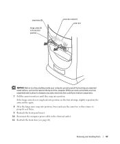
Removing and Installing Parts 67 While you until they snap into position. view slots (2) hinge arms (2) in horizontal position pivot-bar slots (2) pivot bar NOTICE: Before touching anything inside ...
Removing and Installing Parts 67 While you until they snap into position. view slots (2) hinge arms (2) in horizontal position pivot-bar slots (2) pivot bar NOTICE: Before touching anything inside ...

Owner's Manual
Page 68
www.dell.com | support.dell.com Reattaching the Front Door CAUTION: Before you begin any of the procedures in this section, follow the safety instructions located in the Product Information ... on the front door until it clips to both hinge arms. front-door clips (2) frontpanel door hinge arms (2) in vertical position 68 Removing and Installing Parts
www.dell.com | support.dell.com Reattaching the Front Door CAUTION: Before you begin any of the procedures in this section, follow the safety instructions located in the Product Information ... on the front door until it clips to both hinge arms. front-door clips (2) frontpanel door hinge arms (2) in vertical position 68 Removing and Installing Parts
Owner's Manual
Page 69
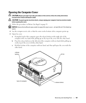
... cover. 1 Follow the procedures in the Product Information Guide. Opening the Computer Cover CAUTION: Before you begin any of computer release button Removing and Installing Parts 69 b Press the release button on the left side of the computer with the other hand.
... cover. 1 Follow the procedures in the Product Information Guide. Opening the Computer Cover CAUTION: Before you begin any of computer release button Removing and Installing Parts 69 b Press the release button on the left side of the computer with the other hand.
Owner's Manual
Page 70
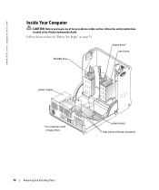
Follow the procedures in the Product Information Guide. www.dell.com | support.dell.com Inside Your Computer CAUTION: Before you begin any of the procedures in this section, follow the safety instructions located in "Before You Begin" on page 59. floppy drive* hard drive CD/DVD drive power supply * On computers with a floppy drive. system board heat sink and blower assembly 70 Removing and Installing Parts
Follow the procedures in the Product Information Guide. www.dell.com | support.dell.com Inside Your Computer CAUTION: Before you begin any of the procedures in this section, follow the safety instructions located in "Before You Begin" on page 59. floppy drive* hard drive CD/DVD drive power supply * On computers with a floppy drive. system board heat sink and blower assembly 70 Removing and Installing Parts
Owner's Manual
Page 71
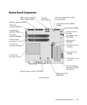
... front panel audio (FP AUD) PCI Express x1 card connector PCI card connectors (PCI SLOT 1, PCI SLOT 2, PCI SLOT 3) telephony connector (TELEPHONY) Removing and Installing Parts 71
... front panel audio (FP AUD) PCI Express x1 card connector PCI card connectors (PCI SLOT 1, PCI SLOT 2, PCI SLOT 3) telephony connector (TELEPHONY) Removing and Installing Parts 71
Owner's Manual
Page 72
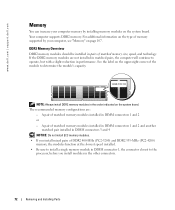
...performance. DDR2 Memory Overview DDR2 memory modules should be installed in pairs of matched memory modules installed in the other connectors. 72 Removing and Installing Parts A pair of matched memory size, speed, and technology. If the DDR2 memory modules are : - Your computer supports DDR2 memory. A ...; If you install mixed pairs of the module to the processor, before you install modules in DIMM connectors 1 and 2 or - www.dell.com | support.dell.com Memory You can increase your computer memory by your computer, see "Memory" on the system board. See the label on the system...
...performance. DDR2 Memory Overview DDR2 memory modules should be installed in pairs of matched memory modules installed in the other connectors. 72 Removing and Installing Parts A pair of matched memory size, speed, and technology. If the DDR2 memory modules are : - Your computer supports DDR2 memory. A ...; If you install mixed pairs of the module to the processor, before you install modules in DIMM connectors 1 and 2 or - www.dell.com | support.dell.com Memory You can increase your computer memory by your computer, see "Memory" on the system board. See the label on the system...
Owner's Manual
Page 73
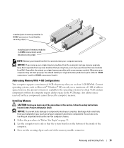
You should install your computer, discharge static electricity from Dell. Removing and Installing Parts 73 however, the amount of memory available to components inside of the computer. 3 Press out the securing clip at each end of the memory module ... you purchased the new modules from your body before you remove your original memory modules from the computer during a memory upgrade, keep them separate from Dell is on its side so that you use four 1-GB DIMMs. Current operating systems, such as Microsoft® Windows® XP, can do not pair...
You should install your computer, discharge static electricity from Dell. Removing and Installing Parts 73 however, the amount of memory available to components inside of the computer. 3 Press out the securing clip at each end of the memory module ... you purchased the new modules from your body before you remove your original memory modules from the computer during a memory upgrade, keep them separate from Dell is on its side so that you use four 1-GB DIMMs. Current operating systems, such as Microsoft® Windows® XP, can do not pair...
Owner's Manual
Page 74
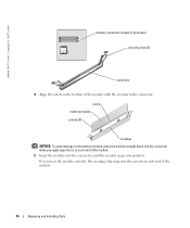
.... If you apply equal force to processor securing clips (2) connector 4 Align the notch on the bottom of the module. 74 Removing and Installing Parts www.dell.com | support.dell.com memory connector closest to each end of the module. 5 Insert the module into the connector until the module snaps into the cutouts at...
.... If you apply equal force to processor securing clips (2) connector 4 Align the notch on the bottom of the module. 74 Removing and Installing Parts www.dell.com | support.dell.com memory connector closest to each end of the module. 5 Insert the module into the connector until the module snaps into the cutouts at...


