Owner's Manual
Page 6
4 Adding Parts Front and Back View of the Computer 70 Front View 70 Back View 72 Reattaching the Front Door and Hinge Arms 75 Reattaching the Hinge ...
4 Adding Parts Front and Back View of the Computer 70 Front View 70 Back View 72 Reattaching the Front Door and Hinge Arms 75 Reattaching the Hinge ...

Owner's Manual
Page 13
... experienced users or technicians. • How to set up a printer • How to troubleshoot and solve problems • How to remove and install parts • How to contact Dell Owner's Manual Documentation and drivers are you looking for? • A diagnostic program for my computer • Drivers for my computer • My computer... documentation • My device documentation Find It Here ResourceCD • How to reinstall drivers (see page 62), run the Dell Diagnostics (see page 58), or access your computer when shipped from...
... experienced users or technicians. • How to set up a printer • How to troubleshoot and solve problems • How to remove and install parts • How to contact Dell Owner's Manual Documentation and drivers are you looking for? • A diagnostic program for my computer • Drivers for my computer • My computer... documentation • My device documentation Find It Here ResourceCD • How to reinstall drivers (see page 62), run the Dell Diagnostics (see page 58), or access your computer when shipped from...
Owner's Manual
Page 60
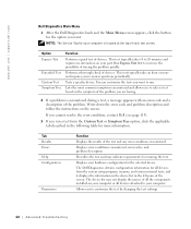
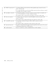
...no interaction on the symptom of each test screen. Tests a specific device. If you cannot resolve the error condition, contact Dell (see page 113). 3 If you want to customize the test by changing the test settings. 60 Advanced Tr oubleshooting The... of the test and any error conditions encountered. Displays your part. Tab Results Errors Help Configuration Parameters Function Displays the results of tracing the problem quickly. www.dell.com | support.dell.com Dell Diagnostics Main Menu 1 After the Dell Diagnostics loads and the Main Menu screen appears, click the ...
...no interaction on the symptom of each test screen. Tests a specific device. If you cannot resolve the error condition, contact Dell (see page 113). 3 If you want to customize the test by changing the test settings. 60 Advanced Tr oubleshooting The... of the test and any error conditions encountered. Displays your part. Tab Results Errors Help Configuration Parameters Function Displays the results of tracing the problem quickly. www.dell.com | support.dell.com Dell Diagnostics Main Menu 1 After the Dell Diagnostics loads and the Main Menu screen appears, click the ...

Owner's Manual
Page 69
SECTION 4 Adding Parts Front and Back View of the Computer Reattaching the Front Door and Hinge Arms Opening the Computer Cover Looking Inside Your Computer Installing and Removing Cards Adding Memory Adding or Replacing the AGP Card Adding a Second Hard Drive Adding a Floppy Drive Closing the Computer Cover
SECTION 4 Adding Parts Front and Back View of the Computer Reattaching the Front Door and Hinge Arms Opening the Computer Cover Looking Inside Your Computer Installing and Removing Cards Adding Memory Adding or Replacing the AGP Card Adding a Second Hard Drive Adding a Floppy Drive Closing the Computer Cover
Owner's Manual
Page 70
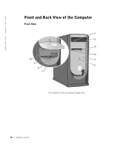
www.dell.com | support.dell.com Front and Back View of the Computer Front View 1 2 3* 4* 10 5 9 6 8 7 *On computers with an optional floppy drive. 70 Adding Parts
www.dell.com | support.dell.com Front and Back View of the Computer Front View 1 2 3* 4* 10 5 9 6 8 7 *On computers with an optional floppy drive. 70 Adding Parts

Owner's Manual
Page 71
...drive light button The floppy-drive light is used to identify your computer when you connect occasionally, such as joysticks or cameras. Adding Parts 71 Press this light turns off the computer. The light might also be on when devices such as your computer emits, such as... system beeps and CDs. Use the front USB connectors for devices that you access the Dell Support website or call technical support. Attach headphones. Instead, perform a Microsoft® Windows® shutdown. 7 service tag 8 headphone connector 9 USB 2.0...
...drive light button The floppy-drive light is used to identify your computer when you connect occasionally, such as joysticks or cameras. Adding Parts 71 Press this light turns off the computer. The light might also be on when devices such as your computer emits, such as... system beeps and CDs. Use the front USB connectors for devices that you access the Dell Support website or call technical support. Attach headphones. Instead, perform a Microsoft® Windows® shutdown. 7 service tag 8 headphone connector 9 USB 2.0...

Owner's Manual
Page 73
... a sound card, the line-in connector 8 video connector 9 optional sound card connector 10 network adapter connector Insert the power cable. network jack modem jack Adding Parts 73 Connect a parallel device, such as a cassette player, CD player, or VCR. (On computers with a network connector card, use Category 5 wiring and connectors for more...
... a sound card, the line-in connector 8 video connector 9 optional sound card connector 10 network adapter connector Insert the power cable. network jack modem jack Adding Parts 73 Connect a parallel device, such as a cassette player, CD player, or VCR. (On computers with a network connector card, use Category 5 wiring and connectors for more...
Owner's Manual
Page 74
... the card.) If you have a USB keyboard, plug it into a USB connector. Use the pink microphone connector to the serial port. 74 Adding Parts www.dell.com | support.dell.com 11 USB 2.0 connectors (6) 12 microphone connector 13 line-out connector 14 center/LFE connector 15 keyboard connector 16 serial connector Use the back...
... the card.) If you have a USB keyboard, plug it into a USB connector. Use the pink microphone connector to the serial port. 74 Adding Parts www.dell.com | support.dell.com 11 USB 2.0 connectors (6) 12 microphone connector 13 line-out connector 14 center/LFE connector 15 keyboard connector 16 serial connector Use the back...

Owner's Manual
Page 75
... above the door bay area by pulling the bottom of the insert with your computer, the front-panel door is designed to pull here Adding Parts 75 front-panel insert use fingers to "break away" if it is lifted up too far. If the front-panel door is open and it...
... above the door bay area by pulling the bottom of the insert with your computer, the front-panel door is designed to pull here Adding Parts 75 front-panel insert use fingers to "break away" if it is lifted up too far. If the front-panel door is open and it...

Owner's Manual
Page 76
... reposition the arms and try again. 8 After the hinge arms snap into position. www.dell.com | support.dell.com 5 Lift both hinge arms to the horizontal position. 6 Use the two view slots to properly seat them. 76 Adding Parts While you work, periodically touch an unpainted metal surface to dissipate any static electricity...
... reposition the arms and try again. 8 After the hinge arms snap into position. www.dell.com | support.dell.com 5 Lift both hinge arms to the horizontal position. 6 Use the two view slots to properly seat them. 76 Adding Parts While you work, periodically touch an unpainted metal surface to dissipate any static electricity...

Owner's Manual
Page 77
... front-panel insert. 10 Reconnect the computer power cable to both hinge arms. front-door clips (2) front-panel door hinge arms (2) in vertical position Adding Parts 77
... front-panel insert. 10 Reconnect the computer power cable to both hinge arms. front-door clips (2) front-panel door hinge arms (2) in vertical position Adding Parts 77

Owner's Manual
Page 78
...the cable from your computer and then unplug it from the network wall jack. 3 Disconnect any of the computer points up. 78 Adding Parts CAUTION: To guard against electrical shock, always unplug your computer from their electrical outlets, and then press the power button to support the ... computer and attached devices did not automatically turn them off . NOTICE: Ensure that sufficient space exists to ground the system board. www.dell.com | support.dell.com Opening the Computer Cover CAUTION: Before you shut down the computer through the Start menu (see page 27). 2 Ensure that the...
...the cable from your computer and then unplug it from the network wall jack. 3 Disconnect any of the computer points up. 78 Adding Parts CAUTION: To guard against electrical shock, always unplug your computer from their electrical outlets, and then press the power button to support the ... computer and attached devices did not automatically turn them off . NOTICE: Ensure that sufficient space exists to ground the system board. www.dell.com | support.dell.com Opening the Computer Cover CAUTION: Before you shut down the computer through the Start menu (see page 27). 2 Ensure that the...

Owner's Manual
Page 79
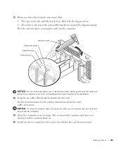
c Hold the bottom of the computer with one hand, and then pull open the cover with the other hand. release button back of the cover with the other hand. 6 Open the cover: a Facing the back of the computer, press the release button on the right side of the computer with one hand while pulling up on the top of computer arrow release button Adding Parts 79 b Press the release button on the left side of the computer with one hand while pulling up on the top of the cover with the other hand.
c Hold the bottom of the computer with one hand, and then pull open the cover with the other hand. release button back of the cover with the other hand. 6 Open the cover: a Facing the back of the computer, press the release button on the right side of the computer with one hand while pulling up on the top of computer arrow release button Adding Parts 79 b Press the release button on the left side of the computer with one hand while pulling up on the top of the cover with the other hand.

Owner's Manual
Page 80
NOTICE: Be careful when opening the computer cover to provide a better view of the inside of drives installed in the figure. 80 Adding Parts drive cables power cables computer cover* (page 78 and page 100) power supply hard drive (page 93) filler brackets for empty card slots (4) (page 82) ... this section, follow the safety instructions on the types of your computer, the cover may not open as widely as shown in your computer. www.dell.com | support.dell.com Looking Inside Your Computer NOTE: The AGP card is removed from the system board.
NOTICE: Be careful when opening the computer cover to provide a better view of the inside of drives installed in the figure. 80 Adding Parts drive cables power cables computer cover* (page 78 and page 100) power supply hard drive (page 93) filler brackets for empty card slots (4) (page 82) ... this section, follow the safety instructions on the types of your computer, the cover may not open as widely as shown in your computer. www.dell.com | support.dell.com Looking Inside Your Computer NOTE: The AGP card is removed from the system board.

Owner's Manual
Page 81
... cable connector (FP_AUDIO) power connector (PWR) telephony voice modem connector (TELE)* CD audio connector (CD)* back of computer *On computers with optional integrated sound. Adding Parts 81
... cable connector (FP_AUDIO) power connector (PWR) telephony voice modem connector (TELE)* CD audio connector (CD)* back of computer *On computers with optional integrated sound. Adding Parts 81

Owner's Manual
Page 82
...system board. CAUTION: To guard against electrical shock, always unplug your computer from the electrical outlet before opening the cover. www.dell.com | support.dell.com Installing and Removing Cards CAUTION: Before you begin any telephone or telecommunication lines from the computer. 5 Disconnect your computer and... them off when you shut down your computer and attached devices are removing but not replacing a card, see page 78). 82 Adding Parts NOTICE: To disconnect a network cable, first unplug the cable from your computer and then unplug it from the network wall jack. 4...
...system board. CAUTION: To guard against electrical shock, always unplug your computer from the electrical outlet before opening the cover. www.dell.com | support.dell.com Installing and Removing Cards CAUTION: Before you begin any telephone or telecommunication lines from the computer. 5 Disconnect your computer and... them off when you shut down your computer and attached devices are removing but not replacing a card, see page 78). 82 Adding Parts NOTICE: To disconnect a network cable, first unplug the cable from your computer and then unplug it from the network wall jack. 4...

Owner's Manual
Page 83
... replacing a card that came with step 10. 9 If you are connected to unplug your computer from its top corners, and ease it for installation. Adding Parts 83 If necessary, disconnect any cards.
... replacing a card that came with step 10. 9 If you are connected to unplug your computer from its top corners, and ease it for installation. Adding Parts 83 If necessary, disconnect any cards.

Owner's Manual
Page 84
If the card is fully seated in the connector and press down firmly. Insert the card firmly into the card guide bracket as you lower the card toward its connector on the system board. not fully seated card fully seated card bracket caught outside of the card into the card connector on the system board. Ensure that the card is full-length, insert the end of slot bracket within slot 84 Adding Parts www.dell.com | support.dell.com 11 Place the card in the slot.
If the card is fully seated in the connector and press down firmly. Insert the card firmly into the card guide bracket as you lower the card toward its connector on the system board. not fully seated card fully seated card bracket caught outside of the card into the card connector on the system board. Ensure that the card is full-length, insert the end of slot bracket within slot 84 Adding Parts www.dell.com | support.dell.com 11 Place the card in the slot.
Owner's Manual
Page 85
Adding Parts 85 NOTICE: To connect a network cable, first plug the cable into the network wall jack and then plug it into place, securing the card(s) in ...
Adding Parts 85 NOTICE: To connect a network cable, first plug the cable into the network wall jack and then plug it into place, securing the card(s) in ...

Owner's Manual
Page 86
... network wall jack and then plug it into place, securing the card(s) in the computer. www.dell.com | support.dell.com Removing a Card CAUTION: Before you need a filler bracket, contact Dell (see page 113). 10 Lower the retention arm and press it into the computer. 11 Close ...you begin any telephone or telecommunication lines from the computer. 4 Disconnect your computer and all attached devices from the operating system. 86 Adding Parts If your computer and attached devices are removing the card permanently, install a filler bracket in this section, follow the safety instructions on . ...
... network wall jack and then plug it into place, securing the card(s) in the computer. www.dell.com | support.dell.com Removing a Card CAUTION: Before you need a filler bracket, contact Dell (see page 113). 10 Lower the retention arm and press it into the computer. 11 Close ...you begin any telephone or telecommunication lines from the computer. 4 Disconnect your computer and all attached devices from the operating system. 86 Adding Parts If your computer and attached devices are removing the card permanently, install a filler bracket in this section, follow the safety instructions on . ...

