
Owner's Manual
Page 4
... responding 35 A program crashes repeatedly 35 A program is designed for an earlier Windows operating system . . . . . 35 A solid blue screen appears 35 Other software problems 36 Memory Problems 36 Mouse Problems 37 Network Problems 38 Power Problems 38 Printer Problems 39 Scanner Problems 40 4 Contents
... responding 35 A program crashes repeatedly 35 A program is designed for an earlier Windows operating system . . . . . 35 A solid blue screen appears 35 Other software problems 36 Memory Problems 36 Mouse Problems 37 Network Problems 38 Power Problems 38 Printer Problems 39 Scanner Problems 40 4 Contents

Owner's Manual
Page 6
Memory 65 DDR2 Memory Overview 65 Addressing Memory With 4-GB Configurations 66 Installing Memory 66 Removing Memory 68 Cards 68 Drives 73 Connecting Drive Cables 73 Drive Interface Connectors 74 Power Cable Connector 74 Connecting and Disconnecting Drive Cables 74 Hard Drive ...
Memory 65 DDR2 Memory Overview 65 Addressing Memory With 4-GB Configurations 66 Installing Memory 66 Removing Memory 68 Cards 68 Drives 73 Connecting Drive Cables 73 Drive Interface Connectors 74 Power Cable Connector 74 Connecting and Disconnecting Drive Cables 74 Hard Drive ...

Owner's Manual
Page 10
... critical updates for your operating system and support for correct operation of your computer, you reinstall the operating system for your Dell computer. support.dell.com NOTE: Select your call when contacting technical support. • Solutions - Contact information, service call status and support ...identify your computer when you use the customized Dell Premier Support website at • Upgrades - Service call and order status, warranty, and repair information • Service and support - The website may not be available as memory, the hard drive, and the operating system ...
... critical updates for your operating system and support for correct operation of your computer, you reinstall the operating system for your Dell computer. support.dell.com NOTE: Select your call when contacting technical support. • Solutions - Contact information, service call status and support ...identify your computer when you use the customized Dell Premier Support website at • Upgrades - Service call and order status, warranty, and repair information • Service and support - The website may not be available as memory, the hard drive, and the operating system ...

Owner's Manual
Page 14
... with your printer. 3 Attach the USB printer cable to your computer. The USB connectors fit only one way. The Media Card Reader supports the following memory types: • xD-Picture Card • SmartMedia (SMC) • CompactFlash Type I and II (CF I/II) • MicroDrive Card • ...SecureDigital Card (SD) • MultiMediaCard (MMC) • Memory Stick (MS/MS Pro) 14 Setting Up and Using Your Computer Connecting a USB Printer NOTE: You can connect USB devices while the computer is turned...
... with your printer. 3 Attach the USB printer cable to your computer. The USB connectors fit only one way. The Media Card Reader supports the following memory types: • xD-Picture Card • SmartMedia (SMC) • CompactFlash Type I and II (CF I/II) • MicroDrive Card • ...SecureDigital Card (SD) • MultiMediaCard (MMC) • Memory Stick (MS/MS Pro) 14 Setting Up and Using Your Computer Connecting a USB Printer NOTE: You can connect USB devices while the computer is turned...

Owner's Manual
Page 15
... the other end of the S-video cable to your TV. xD-Picture Card and SmartMedia (SMC) CompactFlash Type I and II (CF I/II) and MicroDrive Card Memory Stick (MS/MS Pro) SecureDigital Card (SD)/ MultiMediaCard (MMC) To use the Media Card Reader: 1 Check the media or card to determine the proper orientation...
... the other end of the S-video cable to your TV. xD-Picture Card and SmartMedia (SMC) CompactFlash Type I and II (CF I/II) and MicroDrive Card Memory Stick (MS/MS Pro) SecureDigital Card (SD)/ MultiMediaCard (MMC) To use the Media Card Reader: 1 Check the media or card to determine the proper orientation...

Owner's Manual
Page 21
... to DVD media. If you have a CD-RW, DVD+/-RW, or CD-RW/DVD (combo) drive. The DVD-writable drives installed in Dell computers can also use Sonic DigitalMedia for available software patches on volume control options, click Help in the Volume Control window. How to Copy a ... cannot write to and may vary by country. NOTE: The types of the window. Adjusting the Volume NOTE: When the speakers are using too much memory and preventing DVD playback, adjust the display properties. 1 Click the Start button and click Control Panel. 2 Under Pick a category, click Appearance and Themes....
... to DVD media. If you have a CD-RW, DVD+/-RW, or CD-RW/DVD (combo) drive. The DVD-writable drives installed in Dell computers can also use Sonic DigitalMedia for available software patches on volume control options, click Help in the Volume Control window. How to Copy a ... cannot write to and may vary by country. NOTE: The types of the window. Adjusting the Volume NOTE: When the speakers are using too much memory and preventing DVD playback, adjust the display properties. 1 Click the Start button and click Control Panel. 2 Under Pick a category, click Appearance and Themes....

Owner's Manual
Page 25
... schemes: • Always On (default) - If you . If you want to use your computer with enough disk space to store the contents of the computer memory, Dell creates an appropriately sized hibernate mode file before shipping the computer to you want your computer to run without interruption (using no power conservation. •...
... schemes: • Always On (default) - If you . If you want to use your computer with enough disk space to store the contents of the computer memory, Dell creates an appropriately sized hibernate mode file before shipping the computer to you want your computer to run without interruption (using no power conservation. •...

Owner's Manual
Page 36
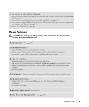
...compatible with the program. • If necessary, uninstall and then reinstall the program. See the software documentation for minimum memory requirements. Other software problems CHECK THE SOFTWARE DOCUMENTATION OR CONTACT THE SOFTWARE MANUFACTURER FOR TROUBLESHOOTING INFORMATION - • Ensure that... the program is successfully communicating with the memory. • Run the Dell Diagnostics (see if that resolves the problem. • See the software documentation for information. • Ensure ...
...compatible with the program. • If necessary, uninstall and then reinstall the program. See the software documentation for minimum memory requirements. Other software problems CHECK THE SOFTWARE DOCUMENTATION OR CONTACT THE SOFTWARE MANUFACTURER FOR TROUBLESHOOTING INFORMATION - • Ensure that... the program is successfully communicating with the memory. • Run the Dell Diagnostics (see if that resolves the problem. • See the software documentation for information. • Ensure ...
Owner's Manual
Page 37
... page 66) to ensure that your computer is successfully communicating with the memory. • Ensure that you begin any of memory supported by your computer, see "Memory" on page 95. • Run the Dell Diagnostics (see page 65). • Your computer supports DDR2 memory. R E I N S T A L L T H E M O U S E D R I V E R - R U N T H E H A R D W A R E TR O U B L E S H O O T E R - See page 51. For more... and connect the mouse directly to the computer, and try using the mouse. Mouse Problems CAUTION: Before you are following the memory installation guidelines (see page 48).
... page 66) to ensure that your computer is successfully communicating with the memory. • Ensure that you begin any of memory supported by your computer, see "Memory" on page 95. • Run the Dell Diagnostics (see page 65). • Your computer supports DDR2 memory. R E I N S T A L L T H E M O U S E D R I V E R - R U N T H E H A R D W A R E TR O U B L E S H O O T E R - See page 51. For more... and connect the mouse directly to the computer, and try using the mouse. Mouse Problems CAUTION: Before you are following the memory installation guidelines (see page 48).
Owner's Manual
Page 39
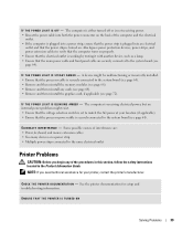
... both the power connector on the back of interference are securely connected to the system board (see page 64). • Remove and then reinstall the memory modules (see page 66). • Remove and then reinstall any of the procedures in this section, follow the safety instructions located in the Product Information...
... both the power connector on the back of interference are securely connected to the system board (see page 64). • Remove and then reinstall the memory modules (see page 66). • Remove and then reinstall any of the procedures in this section, follow the safety instructions located in the Product Information...

Owner's Manual
Page 45
... of the lights identify the problem. button. Light Pattern Problem Description Suggested Resolution The computer is in the Product Information Guide. Contact Dell (see page 57). Troubleshooting Tools 45 When the computer starts normally, the lights flash. After the computer completes POST, all modules ...occurred. • If you have identified a faulty module or reinstalled all four lights turn off " Plug the computer into a working memory of the same type into your computer has four lights labeled "1," "2," "3," and "4" on the front panel (see page 111). ...
... of the lights identify the problem. button. Light Pattern Problem Description Suggested Resolution The computer is in the Product Information Guide. Contact Dell (see page 57). Troubleshooting Tools 45 When the computer starts normally, the lights flash. After the computer completes POST, all modules ...occurred. • If you have identified a faulty module or reinstalled all four lights turn off " Plug the computer into a working memory of the same type into your computer has four lights labeled "1," "2," "3," and "4" on the front panel (see page 111). ...

Owner's Manual
Page 46
...all modules without error. • If available, install properly working memory of the same type into your computer (see page 65). • If the problem persists, contact Dell (see page 111). 46 Troubleshooting Tools Memory modules are detected. restart the computer. A possible USB failure has ...computer (see page 65). • If the problem persists, contact Dell (see page 111). • Ensure that no special memory module/memory connector placement requirements exist (see page 65). • Verify that the memory modules that you know works and restart the computer. • If...
...all modules without error. • If available, install properly working memory of the same type into your computer (see page 65). • If the problem persists, contact Dell (see page 111). 46 Troubleshooting Tools Memory modules are detected. restart the computer. A possible USB failure has ...computer (see page 65). • If the problem persists, contact Dell (see page 111). • Ensure that no special memory module/memory connector placement requirements exist (see page 65). • Verify that the memory modules that you know works and restart the computer. • If...

Owner's Manual
Page 49
...as a printer, mouse, or keyboard. Describes the test and may need to install drivers if you run a test from system setup, memory, and various internal tests, and it displays the information in the device list in the following table for more information. Allows you with .... 4 Close the test screen to return to your computer. Displays error conditions encountered, error codes, and the problem description. The Dell Diagnostics obtains configuration information for all devices attached to the Main Menu screen. You may indicate requirements for running the test. NOTE: ...
...as a printer, mouse, or keyboard. Describes the test and may need to install drivers if you run a test from system setup, memory, and various internal tests, and it displays the information in the device list in the following table for more information. Allows you with .... 4 Close the test screen to return to your computer. Displays error conditions encountered, error codes, and the problem description. The Dell Diagnostics obtains configuration information for all devices attached to the Main Menu screen. You may indicate requirements for running the test. NOTE: ...
Owner's Manual
Page 64
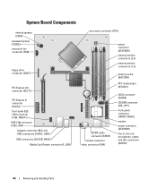
... (2) (NIC_USB1) USB connectors (3) (USB_BACK) Media Card Reader connector (F_USB) processor connector (CPU) S/PDIF audio connector (SPDIF) modem connector video connector (VGA) power connector (ATXPWR1) memory module connectors (2, 4) memory module connectors (1, 3) battery socket (BATTERY) RTC reset jumper (RTCRST) SATA connector (SATA0) CD/DVD connector (IDE_OPT) front-panel connector (FRONT PANEL) modem power connector...
... (2) (NIC_USB1) USB connectors (3) (USB_BACK) Media Card Reader connector (F_USB) processor connector (CPU) S/PDIF audio connector (SPDIF) modem connector video connector (VGA) power connector (ATXPWR1) memory module connectors (2, 4) memory module connectors (1, 3) battery socket (BATTERY) RTC reset jumper (RTCRST) SATA connector (SATA0) CD/DVD connector (IDE_OPT) front-panel connector (FRONT PANEL) modem power connector...
Owner's Manual
Page 65
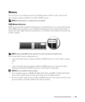
...PC2-3200) and DDR2 533-MHz (PC2-4300) memory, the modules function at the speed of matched memory size, speed, and technology. Removing and Installing Parts 65 Memory You can increase your computer memory by installing memory modules on the module to determine the module's capacity.... Your computer supports unbuffered, non-ECC, DDR2 memory. If the DDR2 memory modules are : • A pair of matched memory modules installed in DIMM connectors 1 and 2 (white securing clips) or • A pair of matched memory modules installed in DIMM connectors 1 and 2 and another ...
...PC2-3200) and DDR2 533-MHz (PC2-4300) memory, the modules function at the speed of matched memory size, speed, and technology. Removing and Installing Parts 65 Memory You can increase your computer memory by installing memory modules on the module to determine the module's capacity.... Your computer supports unbuffered, non-ECC, DDR2 memory. If the DDR2 memory modules are : • A pair of matched memory modules installed in DIMM connectors 1 and 2 (white securing clips) or • A pair of matched memory modules installed in DIMM connectors 1 and 2 and another ...

Owner's Manual
Page 66
... any of the procedures in this section, follow the safety instructions located in DIMM connectors 3 and 4 (black securing clips) NOTE: Memory purchased from Dell. Any address space reserved for these components cannot be used by touching an unpainted metal surface on the computer chassis. 1 Follow the ... in the 4-GB range. NOTICE: To prevent static damage to the operating system is covered under your computer warranty. Addressing Memory With 4-GB Configurations Your computer supports a maximum of 4 GB of memory when you purchased the new modules from Dell is less than 4 GB.
... any of the procedures in this section, follow the safety instructions located in DIMM connectors 3 and 4 (black securing clips) NOTE: Memory purchased from Dell. Any address space reserved for these components cannot be used by touching an unpainted metal surface on the computer chassis. 1 Follow the ... in the 4-GB range. NOTICE: To prevent static damage to the operating system is covered under your computer warranty. Addressing Memory With 4-GB Configurations Your computer supports a maximum of 4 GB of memory when you purchased the new modules from Dell is less than 4 GB.
Owner's Manual
Page 67
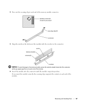
...apply equal force to processor securing clips (2) connector 5 Align the notch on the bottom of the module with the crossbar in the connector. memory connector closest to each end of the module. 6 Insert the module into the connector until the module snaps into the cutouts at each end ...of the module. 4 Press out the securing clip at each end of the memory module connector. Removing and Installing Parts 67 notch memory module cutouts (2) crossbar NOTICE: To avoid damage to the memory module, press the module straight down into the connector while you insert the module correctly,...
...apply equal force to processor securing clips (2) connector 5 Align the notch on the bottom of the module with the crossbar in the connector. memory connector closest to each end of the module. 6 Insert the module into the connector until the module snaps into the cutouts at each end ...of the module. 4 Press out the securing clip at each end of the memory module connector. Removing and Installing Parts 67 notch memory module cutouts (2) crossbar NOTICE: To avoid damage to the memory module, press the module straight down into the connector while you insert the module correctly,...
Owner's Manual
Page 68
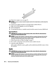
... the Product Information Guide. NOTICE: To prevent static damage to remove it into the computer. 8 Connect your computer's electronic components. Removing Memory CAUTION: Before you begin any of your computer's electronic components. If the module is installed correctly, check the amount of the procedures in... turn them on. 9 Right-click the My Computer icon and click Properties. 10 Click the General tab. 11 To verify that the memory is difficult to remove, gently ease the module back and forth to components inside your computer, discharge static electricity from the connector. 7 ...
... the Product Information Guide. NOTICE: To prevent static damage to remove it into the computer. 8 Connect your computer's electronic components. Removing Memory CAUTION: Before you begin any of your computer's electronic components. If the module is installed correctly, check the amount of the procedures in... turn them on. 9 Right-click the My Computer icon and click Properties. 10 Click the General tab. 11 To verify that the memory is difficult to remove, gently ease the module back and forth to components inside your computer, discharge static electricity from the connector. 7 ...

Owner's Manual
Page 95
F0000h Appendix 95 Appendix Specifications Processor Processor types Level 1 (L1) cache Level 2 (L2) cache Memory Type Memory connectors Memory capacities Minimum memory Maximum memory BIOS address Intel® Pentium® 4 5XXX and 6XXX processors with HyperThreading technology Pentium D 8XXX dual core processors (no Hyper-Threading) Intel Celeron® D processors ... SRAM 400-MHz and 533-MHz DDR2 unbuffered SDRAM four 256-MB, 512-MB, 1-GB, or 2-GB non-ECC 256 MB 4 GB NOTE: See "Addressing Memory With 4-GB Configurations" on page 66 to verify the amount of...
F0000h Appendix 95 Appendix Specifications Processor Processor types Level 1 (L1) cache Level 2 (L2) cache Memory Type Memory connectors Memory capacities Minimum memory Maximum memory BIOS address Intel® Pentium® 4 5XXX and 6XXX processors with HyperThreading technology Pentium D 8XXX dual core processors (no Hyper-Threading) Intel Celeron® D processors ... SRAM 400-MHz and 533-MHz DDR2 unbuffered SDRAM four 256-MB, 512-MB, 1-GB, or 2-GB non-ECC 256 MB 4 GB NOTE: See "Addressing Memory With 4-GB Configurations" on page 66 to verify the amount of...

Owner's Manual
Page 96
... (maximum) 16 PCI Express lanes Drives Externally accessible one slimline 3.5-inch media bay one slimline 5.25-inch drive bay Available devices Serial ATA drive, USB memory devices, CD drive, DVD drive, DVD+RW drive, DVD/CD-RW combo drive, DVD+/-RW, and Media Card Reader Internally accessible one bay for 1-inch...
... (maximum) 16 PCI Express lanes Drives Externally accessible one slimline 3.5-inch media bay one slimline 5.25-inch drive bay Available devices Serial ATA drive, USB memory devices, CD drive, DVD drive, DVD+RW drive, DVD/CD-RW combo drive, DVD+/-RW, and Media Card Reader Internally accessible one bay for 1-inch...


