Owner's Manual
Page 11
...and click the arrow icon. 3 Click the topic that describes your computer, you reinstall the operating system for Dell™ 3.5-inch USB floppy drives, Intel® Pentium® M processors, optical drives, and USB devices. Find it Here • Desktop System Software (DSS)- To download Desktop... System Software: 1 Go to support.dell.com and click Downloads. 2 Enter your Service Tag or product model. 3 In the ...
...and click the arrow icon. 3 Click the topic that describes your computer, you reinstall the operating system for Dell™ 3.5-inch USB floppy drives, Intel® Pentium® M processors, optical drives, and USB devices. Find it Here • Desktop System Software (DSS)- To download Desktop... System Software: 1 Go to support.dell.com and click Downloads. 2 Enter your Service Tag or product model. 3 In the ...
Owner's Manual
Page 27
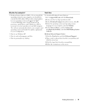
... Hyper-Threading is an Intel® technology that can enhance overall computer performance by allowing one physical processor to function as two logical processors, capable of uses, Dell offers RAID level 1 on your computer. Of the several RAID configurations available in the computer industry for... of performing certain tasks simultaneously. The Intel RAID controller on the Dell Support website at support.dell.com. The drives should be the same size to Processors. If Hyper-Threading is enabled, the processor is optimized to take advantage of Hyper-Threading technology. For more...
... Hyper-Threading is an Intel® technology that can enhance overall computer performance by allowing one physical processor to function as two logical processors, capable of uses, Dell offers RAID level 1 on your computer. Of the several RAID configurations available in the computer industry for... of performing certain tasks simultaneously. The Intel RAID controller on the Dell Support website at support.dell.com. The drives should be the same size to Processors. If Hyper-Threading is enabled, the processor is optimized to take advantage of Hyper-Threading technology. For more...
Owner's Manual
Page 41
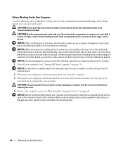
... devices on . E L I M I N A T E I N T E R F E R E N C E - Also bypass power protection devices, power strips, and power extension cables to verify that the computer turns on properly. • Ensure that the processor power cable is securely connected to the system board (see "System Board Components" on page 67). Some possible causes of interference are securely connected to...
... devices on . E L I M I N A T E I N T E R F E R E N C E - Also bypass power protection devices, power strips, and power extension cables to verify that the computer turns on properly. • Ensure that the processor power cable is securely connected to the system board (see "System Board Components" on page 67). Some possible causes of interference are securely connected to...
Owner's Manual
Page 47
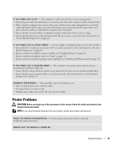
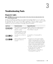
... Product Information Guide. If the computer malfunctions, the color and sequence of the Computer" on page 63). A possible processor failure has Contact Dell (see failure has occurred. After the computer starts, all modules without error. • If available, install properly working... help you troubleshoot a problem, your computer (see "Installing Memory" on page 69). • If the problem persists, contact Dell (see "Contacting Dell" on occurred. When the computer starts normally, the lights flash. The diagnostic lights are detected, but a memory failure has occurred...
... Product Information Guide. If the computer malfunctions, the color and sequence of the Computer" on page 63). A possible processor failure has Contact Dell (see failure has occurred. After the computer starts, all modules without error. • If available, install properly working... help you troubleshoot a problem, your computer (see "Installing Memory" on page 69). • If the problem persists, contact Dell (see "Contacting Dell" on occurred. When the computer starts normally, the lights flash. The diagnostic lights are detected, but a memory failure has occurred...
Owner's Manual
Page 60
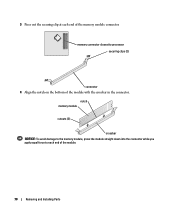
...its pins. NOTICE: When you pull connectors apart, keep them evenly aligned to avoid bending any static electricity that is not authorized by Dell is not covered by its metal mounting bracket. NOTICE: Only a certified service technician should perform repairs on the cable itself. CAUTION: ... NOTICE: Before touching anything inside the computer. 1 Turn off your computer, ground yourself by touching an unpainted metal surface, such as a processor by its edges, not by your computer from their electrical outlets, and then press the power button to ground the system board. if you...
...its pins. NOTICE: When you pull connectors apart, keep them evenly aligned to avoid bending any static electricity that is not authorized by Dell is not covered by its metal mounting bracket. NOTICE: Only a certified service technician should perform repairs on the cable itself. CAUTION: ... NOTICE: Before touching anything inside the computer. 1 Turn off your computer, ground yourself by touching an unpainted metal surface, such as a processor by its edges, not by your computer from their electrical outlets, and then press the power button to ground the system board. if you...
Owner's Manual
Page 67
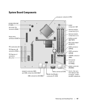
System Board Components processor connector (CPU) password jumper (PSWD) processor fan connector (FAN) floppy drive connector (DSKT2) PCI connectors (2) PCI Express x16 connector (PEG) PCI Express x1 connector (PCI_E1) network connector (NIC) and USB connectors (2) (...
System Board Components processor connector (CPU) password jumper (PSWD) processor fan connector (FAN) floppy drive connector (DSKT2) PCI connectors (2) PCI Express x16 connector (PEG) PCI Express x1 connector (PCI_E1) network connector (NIC) and USB connectors (2) (...
Owner's Manual
Page 68
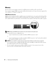
...) memory, the modules function at the slowest speed installed. • Be sure to install a single memory module in DIMM connector 1, the connector closest to the processor, before you install modules in matched pairs, the computer will continue to determine the module's capacity.
...) memory, the modules function at the slowest speed installed. • Be sure to install a single memory module in DIMM connector 1, the connector closest to the processor, before you install modules in matched pairs, the computer will continue to determine the module's capacity.
Owner's Manual
Page 70
3 Press out the securing clip at each end of the module. 70 Removing and Installing Parts memory connector closest to each end of the module with the crossbar in the connector. notch memory module cutouts (2) crossbar NOTICE: To avoid damage to the memory module, press the module straight down into the connector while you apply equal force to processor securing clips (2) connector 4 Align the notch on the bottom of the memory module connector.
3 Press out the securing clip at each end of the module. 70 Removing and Installing Parts memory connector closest to each end of the module with the crossbar in the connector. notch memory module cutouts (2) crossbar NOTICE: To avoid damage to the memory module, press the module straight down into the connector while you apply equal force to processor securing clips (2) connector 4 Align the notch on the bottom of the memory module connector.
Owner's Manual
Page 103
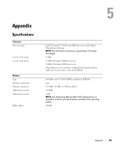
... Memory capacities Minimum memory Maximum memory BIOS address Intel® Pentium® 4 5XXX and 6XXX processors with HyperThreading technology NOTE: Not all Pentium 4 processors support Hyper-Threading technology. 16 KB 1 MB for Pentium 5XXX processors 2 MB for Pentium 6XXX processors (depending on your computer configuration) pipelined-burst, eight-way set associative, write-back SRAM...
... Memory capacities Minimum memory Maximum memory BIOS address Intel® Pentium® 4 5XXX and 6XXX processors with HyperThreading technology NOTE: Not all Pentium 4 processors support Hyper-Threading technology. 16 KB 1 MB for Pentium 5XXX processors 2 MB for Pentium 6XXX processors (depending on your computer configuration) pipelined-burst, eight-way set associative, write-back SRAM...
Owner's Manual
Page 109
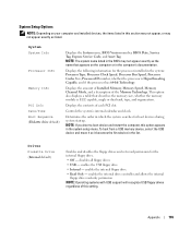
... the contents of the Memory Technology. Displays the following information for the processor installed in the system: Processor Type, Processor Clock Speed, Processor Bus Speed, Processor Cache Size, Processor ID number, whether the processor is ECC capable, single or dual rank, type, and organization. enables...the internal drive controller and allows the internal floppy drive read permission for boot devices during system startup. System System Info Processor Info Memory Info PCI Info Date/Time Boot Sequence (Diskette drive default) Displays the System name, BIOS Version number, ...
... the contents of the Memory Technology. Displays the following information for the processor installed in the system: Processor Type, Processor Clock Speed, Processor Bus Speed, Processor Cache Size, Processor ID number, whether the processor is ECC capable, single or dual rank, type, and organization. enables...the internal drive controller and allows the internal floppy drive read permission for boot devices during system startup. System System Info Processor Info Memory Info PCI Info Date/Time Boot Sequence (Diskette drive default) Displays the System name, BIOS Version number, ...
Owner's Manual
Page 111
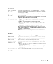
... hard drive operates at its maximum speed. prevents a user without a valid Admin password to performance mode will appear only when a supported processor is not supported by the drive manufacturer. • Performance - Appendix 111 Your computer does not test or change the current acoustics mode.... therefore, this option will cause the drive heads to move faster, causing the hard drive to modify the processor fan and speed based on processor temperature readings. Security Admin Password (Not Set default) System Password (Not Set default) Password Changes (Unlocked default...
... hard drive operates at its maximum speed. prevents a user without a valid Admin password to performance mode will appear only when a supported processor is not supported by the drive manufacturer. • Performance - Appendix 111 Your computer does not test or change the current acoustics mode.... therefore, this option will cause the drive heads to move faster, causing the hard drive to modify the processor fan and speed based on processor temperature readings. Security Admin Password (Not Set default) System Password (Not Set default) Password Changes (Unlocked default...
Owner's Manual
Page 142
... 106 drives, 105 environmental, 107 expansion bus, 104 memory, 103 specifications (continued) physical, 106 power, 106 processor, 103 technical, 103 video, 104 standby mode, 25 support contacting Dell, 120 policy, 118 support website, 10 system board, 67 System Restore, 53-54 system setup about, 107 ...entering, 108 options, 109 screens, 108 T technical support policy, 118 transferring information to a new computer, 27 troubleshooting Dell Diagnostics, 50 diagnostic lights, 47 Hardware Troubleshooter, 53 Help and Support Center, 11 restore to previous state, 53-54 tips, 31 TV ...
... 106 drives, 105 environmental, 107 expansion bus, 104 memory, 103 specifications (continued) physical, 106 power, 106 processor, 103 technical, 103 video, 104 standby mode, 25 support contacting Dell, 120 policy, 118 support website, 10 system board, 67 System Restore, 53-54 system setup about, 107 ...entering, 108 options, 109 screens, 108 T technical support policy, 118 transferring information to a new computer, 27 troubleshooting Dell Diagnostics, 50 diagnostic lights, 47 Hardware Troubleshooter, 53 Help and Support Center, 11 restore to previous state, 53-54 tips, 31 TV ...
Service Manual
Page 3
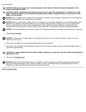
Hold a card by its edges or by your warranty. Damage due to servicing that is not authorized by Dell is not covered by its strain-relief loop, not on the cable itself. CAUTION: To guard against electrical shock, always unplug your computer and then ... unpainted metal surface, such as the metal at the back of cable, press in this type of the computer. personal safety. Hold a component such as a processor by its pins. Some cables have a connector with care.
Hold a card by its edges or by your warranty. Damage due to servicing that is not authorized by Dell is not covered by its strain-relief loop, not on the cable itself. CAUTION: To guard against electrical shock, always unplug your computer and then ... unpainted metal surface, such as the metal at the back of cable, press in this type of the computer. personal safety. Hold a component such as a processor by its pins. Some cables have a connector with care.
Service Manual
Page 11
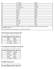
The +3.3 VDC terminals are high current type (9 A current rating/Molex-HCS type). *The +3.3VDC/SE is a brown sense wire for +3.3VDC and is optional. DC Processor Power Connector P2 Pin Number Signal Name 18-AWG Wire 1 COM Black 2 COM Black 3 +12 VADC Yellow 4 +12 VADC Yellow DC Peripheral Connectors P3 and ...
The +3.3 VDC terminals are high current type (9 A current rating/Molex-HCS type). *The +3.3VDC/SE is a brown sense wire for +3.3VDC and is optional. DC Processor Power Connector P2 Pin Number Signal Name 18-AWG Wire 1 COM Black 2 COM Black 3 +12 VADC Yellow 4 +12 VADC Yellow DC Peripheral Connectors P3 and ...
Service Manual
Page 13
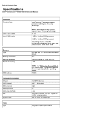
Back to Contents Page Specifications Dell™ Dimension™ 5150/E510 Service Manual Processor Processor type Level 1 (L1) cache Level 2 (L2) cache Memory Type Memory connectors Memory capacities Maximum memory BIOS address Computer Information Chipset RAID Support DMA channels Interrupt ...
Back to Contents Page Specifications Dell™ Dimension™ 5150/E510 Service Manual Processor Processor type Level 1 (L1) cache Level 2 (L2) cache Memory Type Memory connectors Memory capacities Maximum memory BIOS address Computer Information Chipset RAID Support DMA channels Interrupt ...
Service Manual
Page 18
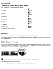
... a slight reduction in the order indicated on the system board. Back to Contents Page Removing and Installing Parts Dell™ Dimension™ 5150/E510 Service Manual Memory Cards Drive Panel Front Panel Drives Hard Drive Floppy Drive Media Card Reader (Optional) CD.../DVD Drive Heat Sink Assembly Processor Fan Assembly Front I/O Panel System Board Power Supply Memory You can increase your Owner's...
... a slight reduction in the order indicated on the system board. Back to Contents Page Removing and Installing Parts Dell™ Dimension™ 5150/E510 Service Manual Memory Cards Drive Panel Front Panel Drives Hard Drive Floppy Drive Media Card Reader (Optional) CD.../DVD Drive Heat Sink Assembly Processor Fan Assembly Front I/O Panel System Board Power Supply Memory You can increase your Owner's...

Service Manual
Page 19
... 4 GB of memory when you install mixed pairs of memory available to components inside your body before you purchased the new modules from Dell is supported. Removing Memory CAUTION: Before you begin any new modules that you touch any of address space; NOTICE: If you remove ... install your computer warranty. NOTE: If you install DDR2 667-MHz memory, the speed is reduced to the processor, before you may not start properly. NOTE: Memory purchased from Dell. Only unbuffered, non-ECC memory is covered under your original memory modules in pairs either in DIMM connectors 1...
... 4 GB of memory when you install mixed pairs of memory available to components inside your body before you purchased the new modules from Dell is supported. Removing Memory CAUTION: Before you begin any new modules that you touch any of address space; NOTICE: If you remove ... install your computer warranty. NOTE: If you install DDR2 667-MHz memory, the speed is reduced to the processor, before you may not start properly. NOTE: Memory purchased from Dell. Only unbuffered, non-ECC memory is covered under your original memory modules in pairs either in DIMM connectors 1...
Service Manual
Page 20
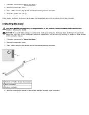
... Guide. NOTICE: To prevent static damage to remove it from your body before you begin any of the memory module connector. 1 memory connector closest to processor 2 securing clips (2) 3 memory connector 4. You can do so by touching an unpainted metal surface on the bottom of the memory module connector. 4. 1. Press out the...
... Guide. NOTICE: To prevent static damage to remove it from your body before you begin any of the memory module connector. 1 memory connector closest to processor 2 securing clips (2) 3 memory connector 4. You can do so by touching an unpainted metal surface on the bottom of the memory module connector. 4. 1. Press out the...
Service Manual
Page 49
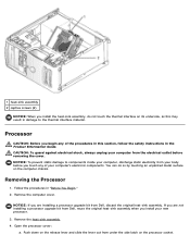
...Push down on the release lever and slide the lever out from Dell, reuse the original heat-sink assembly when you install your computer's electronic components. NOTICE: If you are not installing a processor upgrade kit from under the side latch on the computer chassis. ...NOTICE: To prevent static damage to the thermal interface material. If you are installing a processor upgrade kit from your computer, discharge static electricity from Dell, discard the original heat-sink assembly. CAUTION: To guard against electrical shock, always unplug your computer ...
...Push down on the release lever and slide the lever out from Dell, reuse the original heat-sink assembly when you install your computer's electronic components. NOTICE: If you are not installing a processor upgrade kit from under the side latch on the computer chassis. ...NOTICE: To prevent static damage to the thermal interface material. If you are installing a processor upgrade kit from your computer, discharge static electricity from Dell, discard the original heat-sink assembly. CAUTION: To guard against electrical shock, always unplug your computer ...
Service Manual
Page 50
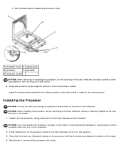
... permanent damage to that the socket is not fully extended, move it from the processor socket. b. Installing the Processor NOTICE: Ground yourself by the edges to remove it to the processor and the computer when you turn on the socket. 4. NOTICE: You must position...and rear alignment notches on the computer. 2. Pull the lever back to release the processor cover. 1 processor cover 4 release lever 2 processor 5 side latch 3 processor socket NOTICE: When removing or replacing the processor, do not touch any objects to touch the underside of the computer. If the release...
... permanent damage to that the socket is not fully extended, move it from the processor socket. b. Installing the Processor NOTICE: Ground yourself by the edges to remove it to the processor and the computer when you turn on the socket. 4. NOTICE: You must position...and rear alignment notches on the computer. 2. Pull the lever back to release the processor cover. 1 processor cover 4 release lever 2 processor 5 side latch 3 processor socket NOTICE: When removing or replacing the processor, do not touch any objects to touch the underside of the computer. If the release...


