Owner's Manual
Page 1
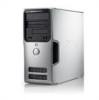
Dell™ Dimension™ 5150/E510 Owner's Manual Service Tag cover latch release CD or DVD eject button CD or DVD activity light FlexBay for optional floppy drive or Media Card Reader microphone connector headphone connector diagnostic lights hard-drive activity light power button/ power activity light USB 2.0 connectors (2) power connector sound connectors (integrated) (5) VGA video connector (integrated) network adapter USB 2.0 connectors (5) Model DCSM card slots for PCI Express x16 (1), PCI (2), PCI Express x1 (1) www.dell.com | support.dell.com
Dell™ Dimension™ 5150/E510 Owner's Manual Service Tag cover latch release CD or DVD eject button CD or DVD activity light FlexBay for optional floppy drive or Media Card Reader microphone connector headphone connector diagnostic lights hard-drive activity light power button/ power activity light USB 2.0 connectors (2) power connector sound connectors (integrated) (5) VGA video connector (integrated) network adapter USB 2.0 connectors (5) Model DCSM card slots for PCI Express x16 (1), PCI (2), PCI Express x1 (1) www.dell.com | support.dell.com
Owner's Manual
Page 5
...Monitor Problems 44 If the screen is blank 44 If the screen is difficult to read 45 3 Troubleshooting Tools Diagnostic Lights 47 Dell Diagnostics 50 Dell Diagnostics Main Menu 50 Drivers 51 What Is a Driver 51 Identifying Drivers 52 Reinstalling Drivers 52 Resolving Software and Hardware... Incompatibilities 53 Restoring Your Operating System 53 Using Microsoft Windows XP System Restore 54 Using Dell PC Restore by Symantec 55 Using the Operating System CD 57 4 Removing and Installing Parts Before You Begin 59 Recommended ...
...Monitor Problems 44 If the screen is blank 44 If the screen is difficult to read 45 3 Troubleshooting Tools Diagnostic Lights 47 Dell Diagnostics 50 Dell Diagnostics Main Menu 50 Drivers 51 What Is a Driver 51 Identifying Drivers 52 Reinstalling Drivers 52 Resolving Software and Hardware... Incompatibilities 53 Restoring Your Operating System 53 Using Microsoft Windows XP System Restore 54 Using Dell PC Restore by Symantec 55 Using the Operating System CD 57 4 Removing and Installing Parts Before You Begin 59 Recommended ...
Owner's Manual
Page 36
... "Resolving Software and Hardware Incompatibilities" on page 47. CHECK THE KEYBOARD CABLE - • Ensure that appears only when the FlexBay device is installed. See "Diagnostic Lights" on page 53. Lockups and Software Problems CAUTION: Before you begin any of the procedures in this section, follow the safety instructions in the BIOS...
... "Resolving Software and Hardware Incompatibilities" on page 47. CHECK THE KEYBOARD CABLE - • Ensure that appears only when the FlexBay device is installed. See "Diagnostic Lights" on page 53. Lockups and Software Problems CAUTION: Before you begin any of the procedures in this section, follow the safety instructions in the BIOS...

Owner's Manual
Page 40
... cable. Power Problems CAUTION: Before you begin any of the procedures in this section, follow the safety instructions in the Product Information Guide. See "Diagnostic Lights" on page 106. C H E C K T H E N E T W O R K L I N G - Contact your network administrator or the person who set up your network to resume normal operation. 40 Solving Problems I F T H E P O W E R L I G H T I S G R E E... B L E S H O O T E R - See "Resolving Software and Hardware Incompatibilities" on the back of network lights, see "Controls and Lights" on page 47. I F T H E P O W E R L I G H T I S B L I...
... cable. Power Problems CAUTION: Before you begin any of the procedures in this section, follow the safety instructions in the Product Information Guide. See "Diagnostic Lights" on page 106. C H E C K T H E N E T W O R K L I N G - Contact your network administrator or the person who set up your network to resume normal operation. 40 Solving Problems I F T H E P O W E R L I G H T I S G R E E... B L E S H O O T E R - See "Resolving Software and Hardware Incompatibilities" on the back of network lights, see "Controls and Lights" on page 47. I F T H E P O W E R L I G H T I S B L I...
Owner's Manual
Page 43
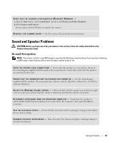
... listed, Windows recognizes the scanner. See the scanner documentation for interference. E N S U R E T H A T T H E S U B W O O F E R A N D T H E S P E A K E R S A R E T U R N E D O N - If you did not turn the player volume down or off nearby fans, fluorescent lights, or halogen lamps to the computer's front-panel headphone connector. See the setup diagram supplied with another device, such as shown on the setup diagram...
... listed, Windows recognizes the scanner. See the scanner documentation for interference. E N S U R E T H A T T H E S U B W O O F E R A N D T H E S P E A K E R S A R E T U R N E D O N - If you did not turn the player volume down or off nearby fans, fluorescent lights, or halogen lamps to the computer's front-panel headphone connector. See the setup diagram supplied with another device, such as shown on the setup diagram...
Owner's Manual
Page 44
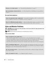
... the headphone cable is normal for bent or broken pins. (It is securely inserted into the headphone connector (see "headphone connector" on . If the power light is off, firmly press the button to have missing pins.) C H E C K T H E M O N I T O R P O W E R L I V E R - Ensure that the monitor is working by testing it with another device, such as shown...
... the headphone cable is normal for bent or broken pins. (It is securely inserted into the headphone connector (see "headphone connector" on . If the power light is off, firmly press the button to have missing pins.) C H E C K T H E M O N I T O R P O W E R L I V E R - Ensure that the monitor is working by testing it with another device, such as shown...
Owner's Manual
Page 45
... the monitor documentation for Screen resolution and Color quality. M O V E T H E S U B W O O F E R A W A Y F R O M T H E M O N I N G S - If your speaker system includes a subwoofer, ensure that the subwoofer is difficult to read C H E C K T H E M O N I T O R S E T T I T O R - Fans, fluorescent lights, halogen lamps, and other electrical devices can cause the screen image to check for interference. ROTATE THE MONITOR TO ELIMINATE SUNLIGHT GLARE AND POSSIBLE INTERFERENCE...
... the monitor documentation for Screen resolution and Color quality. M O V E T H E S U B W O O F E R A W A Y F R O M T H E M O N I N G S - If your speaker system includes a subwoofer, ensure that the subwoofer is difficult to read C H E C K T H E M O N I T O R S E T T I T O R - Fans, fluorescent lights, halogen lamps, and other electrical devices can cause the screen image to check for interference. ROTATE THE MONITOR TO ELIMINATE SUNLIGHT GLARE AND POSSIBLE INTERFERENCE...
Owner's Manual
Page 47
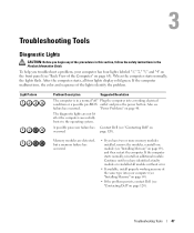
... the Computer" on page 63). A possible processor failure has Contact Dell (see "Contacting Dell" on page 40. Continue until you have identified a faulty module or reinstalled all four lights display solid green. The diagnostic lights are detected, but a memory failure has occurred. • If ... problem, your computer (see "Installing Memory" on page 69). • If the problem persists, contact Dell (see failure has occurred. When the computer starts normally, the lights flash. To help you begin any of the procedures in this section, follow the safety instructions in a ...
... the Computer" on page 63). A possible processor failure has Contact Dell (see "Contacting Dell" on page 40. Continue until you have identified a faulty module or reinstalled all four lights display solid green. The diagnostic lights are detected, but a memory failure has occurred. • If ... problem, your computer (see "Installing Memory" on page 69). • If the problem persists, contact Dell (see failure has occurred. When the computer starts normally, the lights flash. To help you begin any of the procedures in this section, follow the safety instructions in a ...
Owner's Manual
Page 48
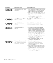
Light Pattern Problem Description A possible graphics card failure has occurred. ... card that you have two or more memory modules installed, remove the modules, reinstall one module (see "Contacting Dell" on page 120). If the computer starts normally, reinstall an additional module. Continue until you are installing are ...are compatible with your computer (see "Installing Memory" on page 69). • If the problem persists, contact Dell (see "Contacting Dell" on page 120). • Ensure that no special memory module/memory connector placement requirements exist (see "DDR2...
Light Pattern Problem Description A possible graphics card failure has occurred. ... card that you have two or more memory modules installed, remove the modules, reinstall one module (see "Contacting Dell" on page 120). If the computer starts normally, reinstall an additional module. Continue until you are installing are ...are compatible with your computer (see "Installing Memory" on page 69). • If the problem persists, contact Dell (see "Contacting Dell" on page 120). • Ensure that no special memory module/memory connector placement requirements exist (see "DDR2...
Owner's Manual
Page 49
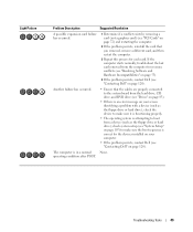
... system is correct for resource conflicts (see "Resolving Software and Hardware Incompatibilities" on page 53). 4 If the problem persists, contact Dell (see "PCI Cards" on page 72) and restarting the computer. 2 If the problem persists, reinstall the card that the cables...starts normally, troubleshoot the last card removed from the hard drive, CD drive, and DVD drive (see "Contacting Dell" on page 120). operating condition after POST. Light Pattern Problem Description Suggested Resolution A possible expansion card failure has occurred. 1 Determine if a conflict exists by removing...
... system is correct for resource conflicts (see "Resolving Software and Hardware Incompatibilities" on page 53). 4 If the problem persists, contact Dell (see "PCI Cards" on page 72) and restarting the computer. 2 If the problem persists, reinstall the card that the cables...starts normally, troubleshoot the last card removed from the hard drive, CD drive, and DVD drive (see "Contacting Dell" on page 120). operating condition after POST. Light Pattern Problem Description Suggested Resolution A possible expansion card failure has occurred. 1 Determine if a conflict exists by removing...
Owner's Manual
Page 61
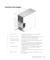
... Press to identify your computer when you access the Dell Support website or call technical support. Use the microphone connector to attach headphones and most kinds of Service Tag 3 CD or DVD eject button 4 CD or DVD activity light 5 FlexBay drive 6 microphone connector 7 headphone connector ... Parts 61 Front View of the Computer 1 2 3 4 5 6 7 8 9 10 11 12 1 cover latch release 2 location of speakers. The drive light is on page 65. On computers with a sound card, the microphone connector is on page 20. See "Removing the Computer Cover" on the card. Can...
... Press to identify your computer when you access the Dell Support website or call technical support. Use the microphone connector to attach headphones and most kinds of Service Tag 3 CD or DVD eject button 4 CD or DVD activity light 5 FlexBay drive 6 microphone connector 7 headphone connector ... Parts 61 Front View of the Computer 1 2 3 4 5 6 7 8 9 10 11 12 1 cover latch release 2 location of speakers. The drive light is on page 65. On computers with a sound card, the microphone connector is on page 20. See "Removing the Computer Cover" on the card. Can...
Owner's Manual
Page 62
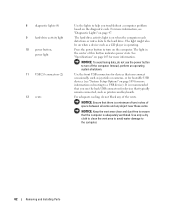
... "Specifications" on when a device such as a CD player is operating. Instead, perform an operating system shutdown. The hard drive activity light is adequately ventilated. NOTICE: Ensure that the computer is on page 47. Use only a dry cloth to clean the vent area to ...inches of space between all vents and any of this button indicates power state. 8 diagnostic lights (4) 9 hard-drive activity light 10 power button, power light 11 USB 2.0 connectors (2) 12 vents Use the lights to help you connect occasionally, such as joysticks or cameras, or for bootable USB devices ...
... "Specifications" on when a device such as a CD player is operating. Instead, perform an operating system shutdown. The hard drive activity light is adequately ventilated. NOTICE: Ensure that the computer is on page 47. Use only a dry cloth to clean the vent area to ...inches of space between all vents and any of this button indicates power state. 8 diagnostic lights (4) 9 hard-drive activity light 10 power button, power light 11 USB 2.0 connectors (2) 12 vents Use the lights to help you connect occasionally, such as joysticks or cameras, or for bootable USB devices ...
Owner's Manual
Page 64
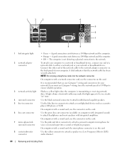
... to 10 Mbps to ensure reliable operation. The computer is recommended that the network cable has been securely attached. Flashes a yellow light when the computer is on the card. On computers with integrated amplifiers. A good connection exists between a 10-Mbps network and...panel of the network cable to the network adapter connector on " state. 1 2 3 4 5 6 7 10 9 8 1 link integrity light 2 network adapter connector 3 network activity light 4 surround connector 5 line-in connector to attach a record/playback device such as a cassette player, CD player, or VCR. NOTE: Do ...
... to 10 Mbps to ensure reliable operation. The computer is recommended that the network cable has been securely attached. Flashes a yellow light when the computer is on the card. On computers with integrated amplifiers. A good connection exists between a 10-Mbps network and...panel of the network cable to the network adapter connector on " state. 1 2 3 4 5 6 7 10 9 8 1 link integrity light 2 network adapter connector 3 network activity light 4 surround connector 5 line-in connector to attach a record/playback device such as a cassette player, CD player, or VCR. NOTE: Do ...

Owner's Manual
Page 106
... indicates a problem with the system board (see the safety instructions 90 to 135 V and 180 to the network. orange light - off (no light) - Blinking green in the Product Information Guide for power-on the system board Power DC power supply: Wattage 305 W Heat...supply rating. If the system cannot boot and there is a solid amber light, this indicates a problem with the power supply inside the computer. Controls and Lights Power button push button Power light green light - solid green for important voltage setting information) Backup battery 3-V CR2032 lithium...
... indicates a problem with the system board (see the safety instructions 90 to 135 V and 180 to the network. orange light - off (no light) - Blinking green in the Product Information Guide for power-on the system board Power DC power supply: Wattage 305 W Heat...supply rating. If the system cannot boot and there is a solid amber light, this indicates a problem with the power supply inside the computer. Controls and Lights Power button push button Power light green light - solid green for important voltage setting information) Backup battery 3-V CR2032 lithium...

Owner's Manual
Page 117
... • Wipe the keyboard, computer, and plastic part of three parts water and one part dishwashing detergent. • To clean your monitor screen, lightly dampen a soft, clean cloth with a swab. Floppy Drive NOTICE: Do not attempt to clean the lens in a straight line from the swab is ...Appendix 117 Do not soak the cloth or let water drip inside the ball cage are dirty, clean the rollers with a cotton swab moistened lightly with the playback quality of your computer or keyboard. You might accidentally misalign the heads, which prevents the drive from dust, fingerprints, and ...
... • Wipe the keyboard, computer, and plastic part of three parts water and one part dishwashing detergent. • To clean your monitor screen, lightly dampen a soft, clean cloth with a swab. Floppy Drive NOTICE: Do not attempt to clean the lens in a straight line from the swab is ...Appendix 117 Do not soak the cloth or let water drip inside the ball cage are dirty, clean the rollers with a cotton swab moistened lightly with the playback quality of your computer or keyboard. You might accidentally misalign the heads, which prevents the drive from dust, fingerprints, and ...
Owner's Manual
Page 139
... PCI, 72 PCI Express, 76 removing PCI, 75 removing PCI Express, 79 slots, 72 types supported, 72 CD/DVD drive activity light, 61 eject button, 61 installing, 98 problems, 32 removing, 96 CD-RW drive problems, 33 CDs, 18 playing, 16 Check ... 18 copying DVDs general information, 18 helpful tips, 20 how to, 18 cover removing, 65 replacing, 101 D Dell contacting, 120 Dell Diagnostics, 50 support policy, 118 support site, 10 diagnostic lights, 47 diagnostics Dell, 50 lights, 47, 62 documentation End User License Agreement, 9 ergonomics, 9 Finding Information, 9 online, 10 Product Information Guide...
... PCI, 72 PCI Express, 76 removing PCI, 75 removing PCI Express, 79 slots, 72 types supported, 72 CD/DVD drive activity light, 61 eject button, 61 installing, 98 problems, 32 removing, 96 CD-RW drive problems, 33 CDs, 18 playing, 16 Check ... 18 copying DVDs general information, 18 helpful tips, 20 how to, 18 cover removing, 65 replacing, 101 D Dell contacting, 120 Dell Diagnostics, 50 support policy, 118 support site, 10 diagnostic lights, 47 diagnostics Dell, 50 lights, 47, 62 documentation End User License Agreement, 9 ergonomics, 9 Finding Information, 9 online, 10 Product Information Guide...
Owner's Manual
Page 140
...DVD drive problems, 32 DVDs, 18 playing, 16 E e-mail problems, 33 End User License Agreement, 9 ergonomics information, 9 error messages diagnostic lights, 47 troubleshooting, 34 F Files and Settings Transfer Wizard, 27 Finding Information, 9 Flex Bay drive Media Card Reader, 61 floppy drive installing,... 91 removing, 89 K keyboard problems, 36 H hard drive activity light, 62 installing, 86 installing second, 88 problems, 33 removing, 85 hardware Dell Diagnostics, 50 Hardware Troubleshooter, 53 headphone connector, 61 Help and Support Center, 11 help file Windows...
...DVD drive problems, 32 DVDs, 18 playing, 16 E e-mail problems, 33 End User License Agreement, 9 ergonomics information, 9 error messages diagnostic lights, 47 troubleshooting, 34 F Files and Settings Transfer Wizard, 27 Finding Information, 9 Flex Bay drive Media Card Reader, 61 floppy drive installing,... 91 removing, 89 K keyboard problems, 36 H hard drive activity light, 62 installing, 86 installing second, 88 problems, 33 removing, 85 hardware Dell Diagnostics, 50 Hardware Troubleshooter, 53 headphone connector, 61 Help and Support Center, 11 help file Windows...
Owner's Manual
Page 141
... hibernate mode, 25-26 managing, 24 options, 25 options, advanced, 26 options, hibernate, 26 options, schemes, 26 problems, 40 standby mode, 25 power light conditions, 40 Power Options Properties, 25 printer cable, 13 connecting, 13 problems, 41 setting up, 13 USB, 13 problems battery, 31 blue screen, 37 ...CD drive, 32 CD-RW drive, 33 computer crashes, 36-37 computer stops responding, 36-37 problems (continued) Dell Diagnostics, 50 diagnostic lights, 47 drives, 32 DVD drive, 32 e-mail, 33 error messages, 34 general, 36 hard drive, 33 Internet, 33 keyboard, 36 Media ...
... hibernate mode, 25-26 managing, 24 options, 25 options, advanced, 26 options, hibernate, 26 options, schemes, 26 problems, 40 standby mode, 25 power light conditions, 40 Power Options Properties, 25 printer cable, 13 connecting, 13 problems, 41 setting up, 13 USB, 13 problems battery, 31 blue screen, 37 ...CD drive, 32 CD-RW drive, 33 computer crashes, 36-37 computer stops responding, 36-37 problems (continued) Dell Diagnostics, 50 diagnostic lights, 47 drives, 32 DVD drive, 32 e-mail, 33 error messages, 34 general, 36 hard drive, 33 Internet, 33 keyboard, 36 Media ...
Owner's Manual
Page 142
...-38 sound problems, 43 volume, 43 speaker problems, 43 volume, 43 specifications audio, 104 computer information, 104 connectors, 105 controls and lights, 106 drives, 105 environmental, 107 expansion bus, 104 memory, 103 specifications (continued) physical, 106 power, 106 processor, 103 technical, ... 107 entering, 108 options, 109 screens, 108 T technical support policy, 118 transferring information to a new computer, 27 troubleshooting Dell Diagnostics, 50 diagnostic lights, 47 Hardware Troubleshooter, 53 Help and Support Center, 11 restore to previous state, 53-54 tips, 31 TV connect to ...
...-38 sound problems, 43 volume, 43 speaker problems, 43 volume, 43 specifications audio, 104 computer information, 104 connectors, 105 controls and lights, 106 drives, 105 environmental, 107 expansion bus, 104 memory, 103 specifications (continued) physical, 106 power, 106 processor, 103 technical, ... 107 entering, 108 options, 109 screens, 108 T technical support policy, 118 transferring information to a new computer, 27 troubleshooting Dell Diagnostics, 50 diagnostic lights, 47 Hardware Troubleshooter, 53 Help and Support Center, 11 restore to previous state, 53-54 tips, 31 TV connect to ...
Service Manual
Page 4
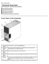
...light is on when the computer reads data from the CD or DVD drive. For more information about the Media Card Reader, see your computer when you access the Dell Service Support website or call technical support. Back to Contents Page Technical Overview Dell™ Dimension™ 5150...the Service Tag to identify your computer Owner's Manual . 6 microphone Use the microphone connector to attach a personal computer microphone for activity light 5 FlexBay Can contain an optional floppy drive or optional Media Card Reader. release 2 location of the Computer 1 cover latch Use ...
...light is on when the computer reads data from the CD or DVD drive. For more information about the Media Card Reader, see your computer when you access the Dell Service Support website or call technical support. Back to Contents Page Technical Overview Dell™ Dimension™ 5150...the Service Tag to identify your computer Owner's Manual . 6 microphone Use the microphone connector to attach a personal computer microphone for activity light 5 FlexBay Can contain an optional floppy drive or optional Media Card Reader. release 2 location of the Computer 1 cover latch Use ...


