Owner's Manual
Page 4
... responding 27 A program crashes repeatedly 27 A program is designed for an earlier Windows operating system. . . . . 27 A solid blue screen appears 27 Other software problems 28 Memory Problems 28 Mouse Problems 29 Network Problems 30 Power Problems 30 Printer Problems 31 Scanner Problems 32 Sound and Speaker Problems 33 No sound from... 34 Video and Monitor Problems 34 If the screen is blank 34 If the screen is difficult to read 35 3 Advanced Troubleshooting Diagnostic Lights 37 Dell Diagnostics 40 Dell Diagnostics Main Menu 41 4 Contents
... responding 27 A program crashes repeatedly 27 A program is designed for an earlier Windows operating system. . . . . 27 A solid blue screen appears 27 Other software problems 28 Memory Problems 28 Mouse Problems 29 Network Problems 30 Power Problems 30 Printer Problems 31 Scanner Problems 32 Sound and Speaker Problems 33 No sound from... 34 Video and Monitor Problems 34 If the screen is blank 34 If the screen is difficult to read 35 3 Advanced Troubleshooting Diagnostic Lights 37 Dell Diagnostics 40 Dell Diagnostics Main Menu 41 4 Contents
Owner's Manual
Page 5
... a Driver 42 Identifying Drivers 42 Reinstalling Drivers 43 Restoring Your Operating System 43 Using Microsoft Windows XP System Restore 43 Using Dell PC Restore by Symantec 45 Resolving Software and Hardware Incompatibilities 46 4 Removing and Installing Parts Before You Begin 47 Recommended Tools... Removing the Computer Cover 54 Inside View of Your Computer 55 System Board Components 56 Memory 57 DDR Memory Overview 57 Addressing Memory With 4-GB Configurations 58 Installing Memory 58 Removing Memory 60 Cards 60 PCI Cards 61 PCI Express Cards 64 Front Panel 69 Removing the ...
... a Driver 42 Identifying Drivers 42 Reinstalling Drivers 43 Restoring Your Operating System 43 Using Microsoft Windows XP System Restore 43 Using Dell PC Restore by Symantec 45 Resolving Software and Hardware Incompatibilities 46 4 Removing and Installing Parts Before You Begin 47 Recommended Tools... Removing the Computer Cover 54 Inside View of Your Computer 55 System Board Components 56 Memory 57 DDR Memory Overview 57 Addressing Memory With 4-GB Configurations 58 Installing Memory 58 Removing Memory 60 Cards 60 PCI Cards 61 PCI Express Cards 64 Front Panel 69 Removing the ...
Owner's Manual
Page 10
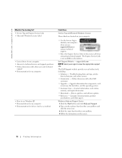
... view the appropriate support site. Online discussion with other Dell customers • Upgrades - Dell Support Website - Troubleshooting hints and tips, articles from technicians, and online courses • Community - Upgrade information for devices (such as memory, the hard drive, and the operating system •...Find it Here Service Tag and Microsoft Windows License These labels are located on the screen. 10 Finding Information www.dell.com | support.dell.com What Are You Looking For? • Service Tag and Express Service Code • Microsoft Windows License Label...
... view the appropriate support site. Online discussion with other Dell customers • Upgrades - Dell Support Website - Troubleshooting hints and tips, articles from technicians, and online courses • Community - Upgrade information for devices (such as memory, the hard drive, and the operating system •...Find it Here Service Tag and Microsoft Windows License These labels are located on the screen. 10 Finding Information www.dell.com | support.dell.com What Are You Looking For? • Service Tag and Express Service Code • Microsoft Windows License Label...
Owner's Manual
Page 28
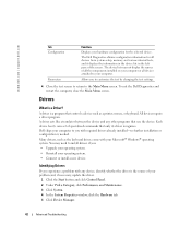
... Ensure that the program is compatible with the memory (see page 57). • Run the Dell Diagnostics (see page 40). If necessary, install additional memory (see page 40). 28 Solving Problems IF YOU EXPERIENCE OTHER MEMORY PROBLEMS - • Reseat the memory modules (see page 57) to ensure that ...your computer. • Ensure that your computer meets the minimum hardware requirements needed to see page 57). • Your Dell Dimension™ computer supports DDR2 memory. BACK UP YOUR FILES IMMEDIATELY USE A VIRUS-SCANNING PROGRAM TO CHECK THE HARD DRIVE, FLOPPY DISKS, OR CDS SAVE ...
... Ensure that the program is compatible with the memory (see page 57). • Run the Dell Diagnostics (see page 40). If necessary, install additional memory (see page 40). 28 Solving Problems IF YOU EXPERIENCE OTHER MEMORY PROBLEMS - • Reseat the memory modules (see page 57) to ensure that ...your computer. • Ensure that your computer meets the minimum hardware requirements needed to see page 57). • Your Dell Dimension™ computer supports DDR2 memory. BACK UP YOUR FILES IMMEDIATELY USE A VIRUS-SCANNING PROGRAM TO CHECK THE HARD DRIVE, FLOPPY DISKS, OR CDS SAVE ...
Owner's Manual
Page 31
... either turned off or is receiving electrical power, but an internal power problem might be malfunctioning or incorrectly installed. • Remove and then reinstall the memory modules (see page 57). • Remove and then reinstall any of the computer and the electrical outlet. • If the computer is plugged into a power...
... either turned off or is receiving electrical power, but an internal power problem might be malfunctioning or incorrectly installed. • Remove and then reinstall the memory modules (see page 57). • Remove and then reinstall any of the computer and the electrical outlet. • If the computer is plugged into a power...
Owner's Manual
Page 38
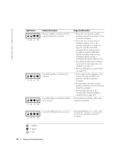
...restart the computer. www.dell.com | support.dell.com Light Pattern ABCD ABCD ABCD Problem Description Memory modules are detected, but a memory failure has occurred. Suggested Resolution • If you have two or more memory modules installed, remove the modules, reinstall one memory module installed, reinstall it...faulty module or reinstalled all modules without error. • If available, install properly working memory of the same type into your computer (see page 57). • If the problem persists, contact Dell (see page 105). • If the computer has a graphics card, remove the ...
...restart the computer. www.dell.com | support.dell.com Light Pattern ABCD ABCD ABCD Problem Description Memory modules are detected, but a memory failure has occurred. Suggested Resolution • If you have two or more memory modules installed, remove the modules, reinstall one memory module installed, reinstall it...faulty module or reinstalled all modules without error. • If available, install properly working memory of the same type into your computer (see page 57). • If the problem persists, contact Dell (see page 105). • If the computer has a graphics card, remove the ...
Owner's Manual
Page 39
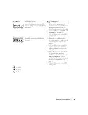
... Hardware Incompatibilities" on page 46). 4 If the problem persists, contact Dell (see page 105). Light Pattern ABCD ABCD = yellow = green = off Problem Description Suggested Resolution Memory modules are detected, but a memory configuration or compatibility error exists. • Ensure that no special memory module/memory connector placement requirements exist (see page 57). • Verify that the...
... Hardware Incompatibilities" on page 46). 4 If the problem persists, contact Dell (see page 105). Light Pattern ABCD ABCD = yellow = green = off Problem Description Suggested Resolution Memory modules are detected, but a memory configuration or compatibility error exists. • Ensure that no special memory module/memory connector placement requirements exist (see page 57). • Verify that the...
Owner's Manual
Page 42
... such as the keyboard driver, come with your hardware configuration for all devices attached to your computer or all devices from system setup, memory, and various internal tests, and it displays the information in the device list in the left pane of specialized commands that use the device.... To exit the Dell Diagnostics and restart the computer, close the Main Menu screen. Dell ships your operating system. • Connect or install a new device. Each device has its driver recognizes. ...
... such as the keyboard driver, come with your hardware configuration for all devices attached to your computer or all devices from system setup, memory, and various internal tests, and it displays the information in the device list in the left pane of specialized commands that use the device.... To exit the Dell Diagnostics and restart the computer, close the Main Menu screen. Dell ships your operating system. • Connect or install a new device. Each device has its driver recognizes. ...
Owner's Manual
Page 56
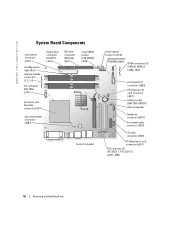
www.dell.com | support.dell.com System Board Components main power connector (J3J1) standby power light CR3J1 memory module connectors (1, 2, 3, 4) fan connector CPU FAN) (J1F1) floppy drive connector (FLOPPY) (J4J1) IDE drive connector (PRI-IDE) J6J1) clear CMOS jumper (CLR CMOS) (J8J3) processor ...
www.dell.com | support.dell.com System Board Components main power connector (J3J1) standby power light CR3J1 memory module connectors (1, 2, 3, 4) fan connector CPU FAN) (J1F1) floppy drive connector (FLOPPY) (J4J1) IDE drive connector (PRI-IDE) J6J1) clear CMOS jumper (CLR CMOS) (J8J3) processor ...
Owner's Manual
Page 57
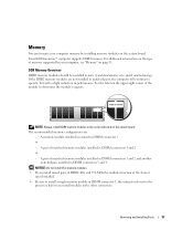
... DIMM connectors 1 and 2 and another matched pair installed in DIMM connectors 3 and 4 NOTICE: Do not install ECC memory modules. • If you install modules in the other connectors. Your Dell Dimension™ computer supports DDR2 memory. A memory module installed in DIMM connectors 1 and 2 or - Removing and Installing Parts 57 See the label on the upper...
... DIMM connectors 1 and 2 and another matched pair installed in DIMM connectors 3 and 4 NOTICE: Do not install ECC memory modules. • If you install modules in the other connectors. Your Dell Dimension™ computer supports DDR2 memory. A memory module installed in DIMM connectors 1 and 2 or - Removing and Installing Parts 57 See the label on the upper...

Owner's Manual
Page 58
... you touch any of the procedures in this section, follow the safety instructions located in DIMM connectors 3 and 4 (black securing clips) NOTE: Memory purchased from Dell. however, the amount of address space; Certain components within the computer require address space in DIMM connectors 1 and 2 or DIMM connectors 3 and 4. NOTICE: To prevent ...
... you touch any of the procedures in this section, follow the safety instructions located in DIMM connectors 3 and 4 (black securing clips) NOTE: Memory purchased from Dell. however, the amount of address space; Certain components within the computer require address space in DIMM connectors 1 and 2 or DIMM connectors 3 and 4. NOTICE: To prevent ...
Owner's Manual
Page 59
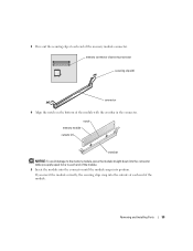
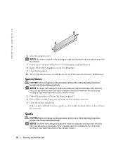
... closest to processor securing clips (2) connector 4 Align the notch on the bottom of the memory module connector. notch memory module cutouts (2) crossbar NOTICE: To avoid damage to each end of the module with the crossbar in the connector. 3 Press out the securing clip at ... each end of the module. 5 Insert the module into the connector until the module snaps into the connector while you apply equal force to the memory module, press the module straight down into position.
... closest to processor securing clips (2) connector 4 Align the notch on the bottom of the memory module connector. notch memory module cutouts (2) crossbar NOTICE: To avoid damage to each end of the module with the crossbar in the connector. 3 Press out the securing clip at ... each end of the module. 5 Insert the module into the connector until the module snaps into the connector while you apply equal force to the memory module, press the module straight down into position.
Owner's Manual
Page 60
.... NOTICE: To prevent static damage to components inside your computer, discharge static electricity from your body before you begin any of memory (RAM) listed. www.dell.com | support.dell.com 6 Close the computer cover. You can do so by touching an unpainted metal surface on . 8 Right-click the... My Computer icon and click Properties. 9 Click the General tab. 10 To verify that the memory is difficult to remove, gently ease the...
.... NOTICE: To prevent static damage to components inside your computer, discharge static electricity from your body before you begin any of memory (RAM) listed. www.dell.com | support.dell.com 6 Close the computer cover. You can do so by touching an unpainted metal surface on . 8 Right-click the... My Computer icon and click Properties. 9 Click the General tab. 10 To verify that the memory is difficult to remove, gently ease the...

Owner's Manual
Page 91
...NOTE: Up to 128 MB of system memory may be allocated to support graphics, depending on system memory size and other factors. 4 GB NOTE: See "Addressing Memory With 4-GB Configurations" on page 58 to verify the amount of memory available to the operating system. Appendix ...Specifications Processor Processor type Level 1 (L1) cache Level 2 (L2) cache Memory Type Memory connectors Memory capacities Minimum memory Maximum memory BIOS address Computer Information Chipset DMA channels Interrupt levels BIOS chip (NVRAM) Intel® Pentium® 4 with HT ...
...NOTE: Up to 128 MB of system memory may be allocated to support graphics, depending on system memory size and other factors. 4 GB NOTE: See "Addressing Memory With 4-GB Configurations" on page 58 to verify the amount of memory available to the operating system. Appendix ...Specifications Processor Processor type Level 1 (L1) cache Level 2 (L2) cache Memory Type Memory connectors Memory capacities Minimum memory Maximum memory BIOS address Computer Information Chipset DMA channels Interrupt levels BIOS chip (NVRAM) Intel® Pentium® 4 with HT ...

Owner's Manual
Page 93
one 3.5-inch drive bay two 5.25-inch drive bays Serial ATA drives, floppy drive, USB memory devices, CD drive, CD-RW drive, DVD drive, DVD-RW drive, and DVD and CD-RW combo drive two bays for 1-inch high hard drives 9-...
one 3.5-inch drive bay two 5.25-inch drive bays Serial ATA drives, floppy drive, USB memory devices, CD drive, CD-RW drive, DVD drive, DVD-RW drive, and DVD and CD-RW combo drive two bays for 1-inch high hard drives 9-...

Owner's Manual
Page 95
....2 to 10,668 m (-50 to 35,000 ft) System Setup Overview Use system setup as the user password • To read the current amount of memory or set the type of hard drive installed Before you use system setup, it is recommended that you write down the system setup screen information...
....2 to 10,668 m (-50 to 35,000 ft) System Setup Overview Use system setup as the user password • To read the current amount of memory or set the type of hard drive installed Before you use system setup, it is recommended that you write down the system setup screen information...

Owner's Manual
Page 97
... number and date, system tags, and other system-specific information. Sets the SATA controller operating mode. Appendix 97 Indicates amount of installed memory, memory speed, channel mode (dual or single), and type of devices specified in this option appears in the boot sequence list. Identifies the drives... a menu to press . Displays current date and time settings. If a boot routine is active (available only for booting from a USB memory device, select the USB device and move it so it becomes the first device in the operating system. Use the Compatible option for hard drives...
... number and date, system tags, and other system-specific information. Sets the SATA controller operating mode. Appendix 97 Indicates amount of installed memory, memory speed, channel mode (dual or single), and type of devices specified in this option appears in the boot sequence list. Identifies the drives... a menu to press . Displays current date and time settings. If a boot routine is active (available only for booting from a USB memory device, select the USB device and move it so it becomes the first device in the operating system. Use the Compatible option for hard drives...

Owner's Manual
Page 98
.... • Suggested - NOTE: Switching to performance mode may cause the drive to be affected. Displays the current status of system memory to disable password security by the drive manufacturer. • Performance - When the field is locked, the option to be restricted with...system setup program in the Options List. • Bypass - www.dell.com | support.dell.com Mouse Port LPT Port Mode LTP Port Address LPT Port DMA Serial Port #1 Video Primary Video Video Memory Size Performance Hyperthreading Performance Security Admin Password System Password Password Status Enables...
.... • Suggested - NOTE: Switching to performance mode may cause the drive to be affected. Displays the current status of system memory to disable password security by the drive manufacturer. • Performance - When the field is locked, the option to be restricted with...system setup program in the Options List. • Bypass - www.dell.com | support.dell.com Mouse Port LPT Port Mode LTP Port Address LPT Port DMA Serial Port #1 Video Primary Video Video Memory Size Performance Hyperthreading Performance Security Admin Password System Password Password Status Enables...

Owner's Manual
Page 99
... setting is reduced or turned off . Change the start-up remotely from suspend mode, hibernate mode, or when powered off for most components, however, system memory remains active. BIOS Update After downloading a new version of the BIOS update file. The options are every day or weekdays (every Monday through Friday). NOTE...
... setting is reduced or turned off . Change the start-up remotely from suspend mode, hibernate mode, or when powered off for most components, however, system memory remains active. BIOS Update After downloading a new version of the BIOS update file. The options are every day or weekdays (every Monday through Friday). NOTE...
Owner's Manual
Page 100
..., to restart your keyboard. The computer attempts to boot from the CD drive. The computer attempts to boot from the primary hard drive. Insert the memory device into a USB port and restart the computer. NOTE: To boot to a USB device, the device must first set the floppy drive to OFF ... | support.dell.com Numlock Key OS Install POST Hotkeys Keyboard Errors This option involves the rightmost bank of keys on your computer to a USB device such as a floppy drive, memory key, or CD-RW drive. When set to Off, this option activates the numeric and mathematical features shown at the top of...
..., to restart your keyboard. The computer attempts to boot from the CD drive. The computer attempts to boot from the primary hard drive. Insert the memory device into a USB port and restart the computer. NOTE: To boot to a USB device, the device must first set the floppy drive to OFF ... | support.dell.com Numlock Key OS Install POST Hotkeys Keyboard Errors This option involves the rightmost bank of keys on your computer to a USB device such as a floppy drive, memory key, or CD-RW drive. When set to Off, this option activates the numeric and mathematical features shown at the top of...


