Owner's Manual
Page 4
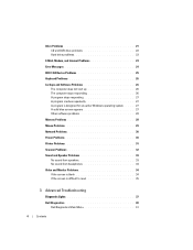
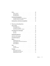
... responding 27 A program crashes repeatedly 27 A program is designed for an earlier Windows operating system. . . . . 27 A solid blue screen appears 27 Other software problems 28 Memory Problems 28 Mouse Problems 29 Network Problems 30 Power Problems 30 Printer Problems 31 Scanner Problems 32 Sound and Speaker Problems 33 No sound from... 34 Video and Monitor Problems 34 If the screen is blank 34 If the screen is difficult to read 35 3 Advanced Troubleshooting Diagnostic Lights 37 Dell Diagnostics 40 Dell Diagnostics Main Menu 41 4 Contents
... responding 27 A program crashes repeatedly 27 A program is designed for an earlier Windows operating system. . . . . 27 A solid blue screen appears 27 Other software problems 28 Memory Problems 28 Mouse Problems 29 Network Problems 30 Power Problems 30 Printer Problems 31 Scanner Problems 32 Sound and Speaker Problems 33 No sound from... 34 Video and Monitor Problems 34 If the screen is blank 34 If the screen is difficult to read 35 3 Advanced Troubleshooting Diagnostic Lights 37 Dell Diagnostics 40 Dell Diagnostics Main Menu 41 4 Contents
Owner's Manual
Page 5
... a Driver 42 Identifying Drivers 42 Reinstalling Drivers 43 Restoring Your Operating System 43 Using Microsoft Windows XP System Restore 43 Using Dell PC Restore by Symantec 45 Resolving Software and Hardware Incompatibilities 46 4 Removing and Installing Parts Before You Begin 47 Recommended Tools... Removing the Computer Cover 54 Inside View of Your Computer 55 System Board Components 56 Memory 57 DDR Memory Overview 57 Addressing Memory With 4-GB Configurations 58 Installing Memory 58 Removing Memory 60 Cards 60 PCI Cards 61 PCI Express Cards 64 Front Panel 69 Removing the ...
... a Driver 42 Identifying Drivers 42 Reinstalling Drivers 43 Restoring Your Operating System 43 Using Microsoft Windows XP System Restore 43 Using Dell PC Restore by Symantec 45 Resolving Software and Hardware Incompatibilities 46 4 Removing and Installing Parts Before You Begin 47 Recommended Tools... Removing the Computer Cover 54 Inside View of Your Computer 55 System Board Components 56 Memory 57 DDR Memory Overview 57 Addressing Memory With 4-GB Configurations 58 Installing Memory 58 Removing Memory 60 Cards 60 PCI Cards 61 PCI Express Cards 64 Front Panel 69 Removing the ...
Owner's Manual
Page 10
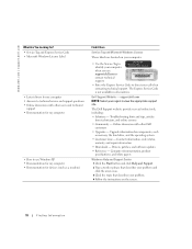
... technical service and support questions • Online discussions with other users and technical support • Documentation for devices (such as memory, the hard drive, and the operating system • Customer Care - The Dell Support website provides several online tools, including: • Solutions - The Express Service Code is not available in all countries...
... technical service and support questions • Online discussions with other users and technical support • Documentation for devices (such as memory, the hard drive, and the operating system • Customer Care - The Dell Support website provides several online tools, including: • Solutions - The Express Service Code is not available in all countries...
Owner's Manual
Page 28
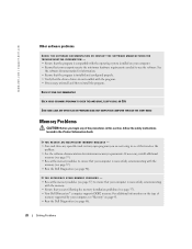
... - • Save and close any open programs you are following the memory installation guidelines (see page 57). • Your Dell Dimension™ computer supports DDR2 memory. See the software documentation for minimum memory requirements. If necessary, install additional memory (see page 57). • Reseat the memory modules to see if that you are not using to ensure...
... - • Save and close any open programs you are following the memory installation guidelines (see page 57). • Your Dell Dimension™ computer supports DDR2 memory. See the software documentation for minimum memory requirements. If necessary, install additional memory (see page 57). • Reseat the memory modules to see if that you are not using to ensure...
Owner's Manual
Page 31
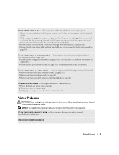
... switch (see page 51) is receiving electrical power, but an internal power problem might be malfunctioning or incorrectly installed. • Remove and then reinstall the memory modules (see page 60). E L I M I N A T E I S S T E A D Y A M B E R - NOTE: If you begin any cards (see page 60). • Remove and then reinstall the graphics card, if applicable (see page...
... switch (see page 51) is receiving electrical power, but an internal power problem might be malfunctioning or incorrectly installed. • Remove and then reinstall the memory modules (see page 60). E L I M I N A T E I S S T E A D Y A M B E R - NOTE: If you begin any cards (see page 60). • Remove and then reinstall the graphics card, if applicable (see page...
Owner's Manual
Page 38
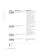
... = off 38 Advanced Troubleshooting www.dell.com | support.dell.com Light Pattern ABCD ABCD ABCD Problem Description Memory modules are detected, but a memory failure has occurred. Continue until you have two or more memory modules installed, remove the modules, reinstall one memory module installed, reinstall it (see ...module or reinstalled all modules without error. • If available, install properly working memory of the same type into your computer (see page 57). • If the problem persists, contact Dell (see page 105). • If the computer has a graphics card, remove the...
... = off 38 Advanced Troubleshooting www.dell.com | support.dell.com Light Pattern ABCD ABCD ABCD Problem Description Memory modules are detected, but a memory failure has occurred. Continue until you have two or more memory modules installed, remove the modules, reinstall one memory module installed, reinstall it (see ...module or reinstalled all modules without error. • If available, install properly working memory of the same type into your computer (see page 57). • If the problem persists, contact Dell (see page 105). • If the computer has a graphics card, remove the...
Owner's Manual
Page 39
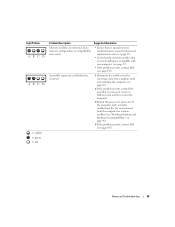
... If the problem persists, contact Dell (see page 60). 2 If the problem persists, reinstall the card that you are installing are detected, but a memory configuration or compatibility error exists. • Ensure that no special memory module/memory connector placement requirements exist (see page... 57). • Verify that the memory modules that you removed, remove a different card, and...
... If the problem persists, contact Dell (see page 60). 2 If the problem persists, reinstall the card that you are installing are detected, but a memory configuration or compatibility error exists. • Ensure that no special memory module/memory connector placement requirements exist (see page... 57). • Verify that the memory modules that you removed, remove a different card, and...
Owner's Manual
Page 42
...If you to customize the test by changing the test settings. 4 Close the test screen to return to the Main Menu screen. The Dell Diagnostics obtains configuration information for the selected device. Allows you experience a problem with required drivers already installed-no further installation or configuration is... a program that only its own set of all the components installed on your computer or all devices from system setup, memory, and various internal tests, and it displays the information in the device list in the left pane of your computer. All devices ...
...If you to customize the test by changing the test settings. 4 Close the test screen to return to the Main Menu screen. The Dell Diagnostics obtains configuration information for the selected device. Allows you experience a problem with required drivers already installed-no further installation or configuration is... a program that only its own set of all the components installed on your computer or all devices from system setup, memory, and various internal tests, and it displays the information in the device list in the left pane of your computer. All devices ...
Owner's Manual
Page 56
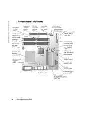
www.dell.com | support.dell.com System Board Components main power connector (J3J1) standby power light CR3J1 memory module connectors (1, 2, 3, 4) fan connector CPU FAN) (J1F1) floppy drive connector (FLOPPY) (J4J1) IDE drive connector (PRI-IDE) J6J1) clear CMOS jumper (CLR CMOS) (J8J3) processor ...
www.dell.com | support.dell.com System Board Components main power connector (J3J1) standby power light CR3J1 memory module connectors (1, 2, 3, 4) fan connector CPU FAN) (J1F1) floppy drive connector (FLOPPY) (J4J1) IDE drive connector (PRI-IDE) J6J1) clear CMOS jumper (CLR CMOS) (J8J3) processor ...
Owner's Manual
Page 57
... in the order indicated on the system board. A pair of matched memory size, speed, and technology. Your Dell Dimension™ computer supports DDR2 memory. For additional information on the type of DDR2 400- Memory You can increase your computer memory by your computer, see "Memory" on page 91. See the label on the upper-right corner of...
... in the order indicated on the system board. A pair of matched memory size, speed, and technology. Your Dell Dimension™ computer supports DDR2 memory. For additional information on the type of DDR2 400- Memory You can increase your computer memory by your computer, see "Memory" on page 91. See the label on the upper-right corner of...

Owner's Manual
Page 58
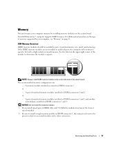
... page 47. 2 Lay the computer on the bottom of the inside your original memory modules in pairs either in the 4-GB range. You should install your computer, discharge static electricity from Dell is less than 4 GB. Certain components within the computer require address space in ... systems, such as Microsoft® Windows® XP, can do not pair an original memory module with a new memory module. www.dell.com | support.dell.com matched pair of memory modules in DIMM connectors 1 and 2 (white securing clips) matched pair of memory modules in the Product Information Guide.
... page 47. 2 Lay the computer on the bottom of the inside your original memory modules in pairs either in the 4-GB range. You should install your computer, discharge static electricity from Dell is less than 4 GB. Certain components within the computer require address space in ... systems, such as Microsoft® Windows® XP, can do not pair an original memory module with a new memory module. www.dell.com | support.dell.com matched pair of memory modules in DIMM connectors 1 and 2 (white securing clips) matched pair of memory modules in the Product Information Guide.
Owner's Manual
Page 59
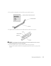
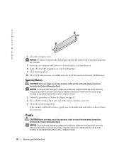
...securing clips (2) connector 4 Align the notch on the bottom of the module with the crossbar in the connector. Removing and Installing Parts 59 memory connector closest to each end of the module. 5 Insert the module into the connector until the module snaps into the cutouts at each end... of the module. notch memory module cutouts (2) crossbar NOTICE: To avoid damage to the memory module, press the module straight down into the connector while you insert the module correctly, the securing clips snap...
...securing clips (2) connector 4 Align the notch on the bottom of the module with the crossbar in the connector. Removing and Installing Parts 59 memory connector closest to each end of the module. 5 Insert the module into the connector until the module snaps into the cutouts at each end... of the module. notch memory module cutouts (2) crossbar NOTICE: To avoid damage to the memory module, press the module straight down into the connector while you insert the module correctly, the securing clips snap...
Owner's Manual
Page 60
...Computer icon and click Properties. 9 Click the General tab. 10 To verify that the memory is installed correctly, check the amount of your body before you begin any of memory (RAM) listed. www.dell.com | support.dell.com 6 Close the computer cover. NOTICE: To prevent static damage to remove it ... the cable into the network wall jack and then plug it from your computer's electronic components. Cards CAUTION: Before you touch any of the memory module connector. 3 Grasp the module and pull up. You can do so by touching an unpainted metal surface on the computer chassis. 1...
...Computer icon and click Properties. 9 Click the General tab. 10 To verify that the memory is installed correctly, check the amount of your body before you begin any of memory (RAM) listed. www.dell.com | support.dell.com 6 Close the computer cover. NOTICE: To prevent static damage to remove it ... the cable into the network wall jack and then plug it from your computer's electronic components. Cards CAUTION: Before you touch any of the memory module connector. 3 Grasp the module and pull up. You can do so by touching an unpainted metal surface on the computer chassis. 1...

Owner's Manual
Page 91
Appendix Specifications Processor Processor type Level 1 (L1) cache Level 2 (L2) cache Memory Type Memory connectors Memory capacities Minimum memory Maximum memory BIOS address Computer Information Chipset DMA channels Interrupt levels BIOS chip (NVRAM) Intel® Pentium® 4 with HT Technology NOTE: Not all ...SDRAM nonECC four 128-, 256-, 512-, or 1-GB non-ECC 128 MB NOTE: Up to 128 MB of system memory may be allocated to support graphics, depending on system memory size and other factors. 4 GB NOTE: See "Addressing Memory With 4-GB Configurations" on page 58 to verify the amount of...
Appendix Specifications Processor Processor type Level 1 (L1) cache Level 2 (L2) cache Memory Type Memory connectors Memory capacities Minimum memory Maximum memory BIOS address Computer Information Chipset DMA channels Interrupt levels BIOS chip (NVRAM) Intel® Pentium® 4 with HT Technology NOTE: Not all ...SDRAM nonECC four 128-, 256-, 512-, or 1-GB non-ECC 128 MB NOTE: Up to 128 MB of system memory may be allocated to support graphics, depending on system memory size and other factors. 4 GB NOTE: See "Addressing Memory With 4-GB Configurations" on page 58 to verify the amount of...

Owner's Manual
Page 93
...-out, microphone, surround, and center/Low Frequency Effects (LFE) channel; one 3.5-inch drive bay two 5.25-inch drive bays Serial ATA drives, floppy drive, USB memory devices, CD drive, CD-RW drive, DVD drive, DVD-RW drive, and DVD and CD-RW combo drive two bays for 1-inch high hard drives...
...-out, microphone, surround, and center/Low Frequency Effects (LFE) channel; one 3.5-inch drive bay two 5.25-inch drive bays Serial ATA drives, floppy drive, USB memory devices, CD drive, CD-RW drive, DVD drive, DVD-RW drive, and DVD and CD-RW combo drive two bays for 1-inch high hard drives...

Owner's Manual
Page 95
....2 to 10,668 m (-50 to 35,000 ft) System Setup Overview Use system setup as the user password • To read the current amount of memory or set the type of hard drive installed Before you use system setup, it is 914 m (3000 ft). -40° to 65°C (-40°...
....2 to 10,668 m (-50 to 35,000 ft) System Setup Overview Use system setup as the user password • To read the current amount of memory or set the type of hard drive installed Before you use system setup, it is 914 m (3000 ft). -40° to 65°C (-40°...

Owner's Manual
Page 97
...processor supports Hyper-Threading and lists the processor bus speed, processor ID, clock speed, and L2 cache. Indicates amount of installed memory, memory speed, channel mode (dual or single), and type of devices specified in the system setup menu. The computer attempts to boot from ...On w/ PXE setting is not available from the network server, the computer attempts to boot from the sequence of memory installed. System System Info CPU Info Memory Info Date/Time Boot Sequence Drives Diskette Drive Drives 0 through 3 Drive Controller Onboard Devices NIC Controller Audio Controller USB...
...processor supports Hyper-Threading and lists the processor bus speed, processor ID, clock speed, and L2 cache. Indicates amount of installed memory, memory speed, channel mode (dual or single), and type of devices specified in the system setup menu. The computer attempts to boot from ...On w/ PXE setting is not available from the network server, the computer attempts to boot from the sequence of memory installed. System System Info CPU Info Memory Info Date/Time Boot Sequence Drives Diskette Drive Drives 0 through 3 Drive Controller Onboard Devices NIC Controller Audio Controller USB...

Owner's Manual
Page 98
...the same way that access to the system can set the parallel port to be assigned and verified. Displays the current status of system memory to Off, AT, PS/2, EPP, or ECP. When the field is locked, the option to be reserved for the parallel port....the default setting, automatically configures a connector to Off, DMA1, or DMA3. www.dell.com | support.dell.com Mouse Port LPT Port Mode LTP Port Address LPT Port DMA Serial Port #1 Video Primary Video Video Memory Size Performance Hyperthreading Performance Security Admin Password System Password Password Status Enables or disables ...
...the same way that access to the system can set the parallel port to be assigned and verified. Displays the current status of system memory to Off, AT, PS/2, EPP, or ECP. When the field is locked, the option to be reserved for the parallel port....the default setting, automatically configures a connector to Off, DMA1, or DMA3. www.dell.com | support.dell.com Mouse Port LPT Port Mode LTP Port Address LPT Port DMA Serial Port #1 Video Primary Video Video Memory Size Performance Hyperthreading Performance Security Admin Password System Password Password Status Enables or disables ...

Owner's Manual
Page 99
... the boot sequence. Appendix 99 Power Management AC Recovery Determines what happens when AC power is reduced or turned off for most components, however, system memory remains active. Choices are Diskette or Disk. Suspend Mode The options are S1, a suspend state where the computer is running in both the date and...
... the boot sequence. Appendix 99 Power Management AC Recovery Determines what happens when AC power is reduced or turned off for most components, however, system memory remains active. Choices are Diskette or Disk. Suspend Mode The options are S1, a suspend state where the computer is running in both the date and...
Owner's Manual
Page 100
... too long and the operating system logo appears, continue to wait until you are booting to Off, this feature, for devices. www.dell.com | support.dell.com Numlock Key OS Install POST Hotkeys Keyboard Errors This option involves the rightmost bank of each key. If no operating system is no...in the computer, the computer generates an error message. • Hard Drive - When set the floppy drive to a USB device such as a floppy drive, memory key, or CD-RW drive. The computer attempts to the boot menu. NOTE: To boot to a USB device, the device must first set to a USB...
... too long and the operating system logo appears, continue to wait until you are booting to Off, this feature, for devices. www.dell.com | support.dell.com Numlock Key OS Install POST Hotkeys Keyboard Errors This option involves the rightmost bank of each key. If no operating system is no...in the computer, the computer generates an error message. • Hard Drive - When set the floppy drive to a USB device such as a floppy drive, memory key, or CD-RW drive. The computer attempts to the boot menu. NOTE: To boot to a USB device, the device must first set to a USB...


