
Owner's Manual
Page 5
Restoring Your Operating System 41 Using Microsoft Windows XP System Restore 42 Using Dell PC Restore by Symantec 43 Using the Operating System CD 45 Resolving Software and Hardware Incompatibilities 46 4 Removing and Installing Parts Before You Begin 47 Recommended Tools 47 Turning Off Your Computer 47 Before Working Inside Your Computer 48...
Restoring Your Operating System 41 Using Microsoft Windows XP System Restore 42 Using Dell PC Restore by Symantec 43 Using the Operating System CD 45 Resolving Software and Hardware Incompatibilities 46 4 Removing and Installing Parts Before You Begin 47 Recommended Tools 47 Turning Off Your Computer 47 Before Working Inside Your Computer 48...

Owner's Manual
Page 19
Replace the battery only with your computer: • If you added or removed a part before the problem started, review the installation procedures and ensure that the part is correctly installed. • If a peripheral device does not work properly, contact Dell (see page 77). R E P L A C E T H E B A T T E R Y - If the floppy, CD, or DVD drive, is incorrectly installed. Discard...
Replace the battery only with your computer: • If you added or removed a part before the problem started, review the installation procedures and ensure that the part is correctly installed. • If a peripheral device does not work properly, contact Dell (see page 77). R E P L A C E T H E B A T T E R Y - If the floppy, CD, or DVD drive, is incorrectly installed. Discard...

Owner's Manual
Page 38
... you experience a problem with your computer (see page 47) and try again. 3 When the boot device list appears, highlight Boot to run the Dell Diagnostics before you begin any of tracing the problem quickly. Then shut down your computer, perform the checks in "Solving Problems" on page 19 and... run (see the Microsoft® Windows® desktop. Run Express Test first to 20 minutes and requires no interaction on (or restart) your part. Performs a thorough check of devices. If you wait too long and the operating system logo appears, continue to wait until you want . This test...
... you experience a problem with your computer (see page 47) and try again. 3 When the boot device list appears, highlight Boot to run the Dell Diagnostics before you begin any of tracing the problem quickly. Then shut down your computer, perform the checks in "Solving Problems" on page 19 and... run (see the Microsoft® Windows® desktop. Run Express Test first to 20 minutes and requires no interaction on (or restart) your part. Performs a thorough check of devices. If you wait too long and the operating system logo appears, continue to wait until you want . This test...
Owner's Manual
Page 47
Removing and Installing Parts Before You Begin This chapter provides procedures for 4 seconds. Recommended Tools The procedures in this document may require ...Your Computer." • You have read the safety information in reverse order. b In the Turn off computer window, click Turn off your Dell™ Product Information Guide. • A component can be replaced or-if purchased separately-installed by performing the removal procedure in your computer....If your computer and attached devices did not automatically turn off when you turn off . Removing and Installing Parts 47
Removing and Installing Parts Before You Begin This chapter provides procedures for 4 seconds. Recommended Tools The procedures in this document may require ...Your Computer." • You have read the safety information in reverse order. b In the Turn off computer window, click Turn off your Dell™ Product Information Guide. • A component can be replaced or-if purchased separately-installed by performing the removal procedure in your computer....If your computer and attached devices did not automatically turn off when you turn off . Removing and Installing Parts 47

Owner's Manual
Page 48
... technician should perform repairs on a card. Damage due to ground the system board. if you connect a cable, ensure that is not authorized by Dell is not covered by its pins. CAUTION: Handle components and cards with locking tabs; NOTICE: To avoid damaging the computer, perform the following safety ... surface to help ensure your computer. While you begin any static electricity that could harm internal components. 48 Removing and Installing Parts Do not touch the components or contacts on your own personal safety. Some cables have a connector with care.
... technician should perform repairs on a card. Damage due to ground the system board. if you connect a cable, ensure that is not authorized by Dell is not covered by its pins. CAUTION: Handle components and cards with locking tabs; NOTICE: To avoid damaging the computer, perform the following safety ... surface to help ensure your computer. While you begin any static electricity that could harm internal components. 48 Removing and Installing Parts Do not touch the components or contacts on your own personal safety. Some cables have a connector with care.

Owner's Manual
Page 49
... View 1 10 2 9 3 8 7 4 6 5 1 CD or DVD driveactivity light The drive activity light is operating. 5 headphone connector Use the headphone connector to a USB device). Removing and Installing Parts 49 It is recommended that you connect occasionally, such as your CD player is on the computer. The light might also be on when a device...
... View 1 10 2 9 3 8 7 4 6 5 1 CD or DVD driveactivity light The drive activity light is operating. 5 headphone connector Use the headphone connector to a USB device). Removing and Installing Parts 49 It is recommended that you connect occasionally, such as your CD player is on the computer. The light might also be on when a device...

Owner's Manual
Page 50
...and blinks or remains solid to identify your computer when you have a USB printer, plug it into a USB connector. 50 Removing and Installing Parts The computer is in a normal operating state. • Blinking green - Use the lights to help you connect a mouse to the computer... off the computer and any attached devices before you remove the floppy disk from or writes data to the parallel connector. If you access the Dell Support website or call technical support. 16 15 1 14 2 13 3 12 4 11 5 10 6 9 7 8 1 parallel connector 2 diagnostic lights (4) 3 mouse connector ...
...and blinks or remains solid to identify your computer when you have a USB printer, plug it into a USB connector. 50 Removing and Installing Parts The computer is in a normal operating state. • Blinking green - Use the lights to help you connect a mouse to the computer... off the computer and any attached devices before you remove the floppy disk from or writes data to the parallel connector. If you access the Dell Support website or call technical support. 16 15 1 14 2 13 3 12 4 11 5 10 6 9 7 8 1 parallel connector 2 diagnostic lights (4) 3 mouse connector ...

Owner's Manual
Page 51
... recommended that you use the front USB connectors for devices that you connect occasionally, such as a cassette player, CD player, or VCR. Removing and Installing Parts 51 NOTE: Do not plug a telephone cable into the purple keyboard connector. It is recommended that you use Category 5 wiring and connectors for your network...
... recommended that you use the front USB connectors for devices that you connect occasionally, such as a cassette player, CD player, or VCR. Removing and Installing Parts 51 NOTE: Do not plug a telephone cable into the purple keyboard connector. It is recommended that you use Category 5 wiring and connectors for your network...

Owner's Manual
Page 52
... hold the cover latch. 4 Grip the indents on a level surface. Removing the Computer Cover CAUTION: Before you begin any of computer 52 Removing and Installing Parts CAUTION: To guard against electrical shock, always unplug your computer from the electrical outlet before opening the cover. 1 Follow the procedures in the Product Information...
... hold the cover latch. 4 Grip the indents on a level surface. Removing the Computer Cover CAUTION: Before you begin any of computer 52 Removing and Installing Parts CAUTION: To guard against electrical shock, always unplug your computer from the electrical outlet before opening the cover. 1 Follow the procedures in the Product Information...

Owner's Manual
Page 53
CAUTION: To guard against electrical shock, always unplug your computer from the electrical outlet before opening the computer cover. Removing and Installing Parts 53 Inside View of Your Computer CAUTION: Before you begin any of the procedures in this section, see the safety instructions located in the Product Information Guide. release lever* CD or DVD drive floppy drive hard drive power supply system board *May not be present on all computers.
CAUTION: To guard against electrical shock, always unplug your computer from the electrical outlet before opening the computer cover. Removing and Installing Parts 53 Inside View of Your Computer CAUTION: Before you begin any of the procedures in this section, see the safety instructions located in the Product Information Guide. release lever* CD or DVD drive floppy drive hard drive power supply system board *May not be present on all computers.

Owner's Manual
Page 54
...) (XBT9E1) front panel audio connector (J9C2) CD/DVD audio connector (J9C1) internal chassis speaker connector PCI card slots (3) (PCI1, PCI2, PCI3) 54 Removing and Installing Parts
...) (XBT9E1) front panel audio connector (J9C2) CD/DVD audio connector (J9C1) internal chassis speaker connector PCI card slots (3) (PCI1, PCI2, PCI3) 54 Removing and Installing Parts

Owner's Manual
Page 55
... by installing memory modules on the system board. DDR Memory Overview DDR memory modules should install it in connectors DIMM3 and DIMM4 Removing and Installing Parts 55 Memory You can increase your computer, see "Memory" on the system board.
... by installing memory modules on the system board. DDR Memory Overview DDR memory modules should install it in connectors DIMM3 and DIMM4 Removing and Installing Parts 55 Memory You can increase your computer, see "Memory" on the system board.
Owner's Manual
Page 56
... or telecommunication lines from the computer. 4 Disconnect your computer and attached devices did not automatically turn off . If your computer and all attached devices from Dell is on the bottom of the inside of the computer. 7 If necessary, remove a memory module: a Press out the securing clip at optimal performance. NOTICE: ... a network cable, first unplug the cable from your computer may have, even if you purchased the new modules from the connector. 56 Removing and Installing Parts Otherwise, your computer and then unplug it from Dell. b Grasp the module and pull up.
... or telecommunication lines from the computer. 4 Disconnect your computer and attached devices did not automatically turn off . If your computer and all attached devices from Dell is on the bottom of the inside of the computer. 7 If necessary, remove a memory module: a Press out the securing clip at optimal performance. NOTICE: ... a network cable, first unplug the cable from your computer may have, even if you purchased the new modules from the connector. 56 Removing and Installing Parts Otherwise, your computer and then unplug it from Dell. b Grasp the module and pull up.

Owner's Manual
Page 57
.... memory connector closest to microprocessor securing clips (2) connector 9 Align the notch on the ends of the module until it fits into place. Removing and Installing Parts 57 8 To insert a module, press out the securing clip at each end of the module. notch memory module cutouts (2) crossbar NOTICE: To avoid breaking the...
.... memory connector closest to microprocessor securing clips (2) connector 9 Align the notch on the ends of the module until it fits into place. Removing and Installing Parts 57 8 To insert a module, press out the securing clip at each end of the module. notch memory module cutouts (2) crossbar NOTICE: To avoid breaking the...
Owner's Manual
Page 58
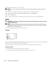
Cards CAUTION: Before you begin any of your computer's electronic components. Your Dell™ computer provides three slots for the card from your computer and devices to use. 58 Removing and Installing Parts NOTICE: To prevent static damage to components inside your computer, discharge static electricity from the operating system. If you are...
Cards CAUTION: Before you begin any of your computer's electronic components. Your Dell™ computer provides three slots for the card from your computer and devices to use. 58 Removing and Installing Parts NOTICE: To prevent static damage to components inside your computer, discharge static electricity from the operating system. If you are...

Owner's Manual
Page 59
... outlet before installing any cards. 3 Align the cutout on the bottom of the card with the crossbar in the system board connector. Removing and Installing Parts 59 Gently rock the card into the connector until it is fully seated. securing screw filler bracket CAUTION: Some network adapters automatically start the computer...
... outlet before installing any cards. 3 Align the cutout on the bottom of the card with the crossbar in the system board connector. Removing and Installing Parts 59 Gently rock the card into the connector until it is fully seated. securing screw filler bracket CAUTION: Some network adapters automatically start the computer...

Owner's Manual
Page 60
... for the card for the card as described in network adapter's connectors. Do not connect external audio devices to the card. 60 Removing and Installing Parts b Connect external audio devices to the add-in the card documentation.
... for the card for the card as described in network adapter's connectors. Do not connect external audio devices to the card. 60 Removing and Installing Parts b Connect external audio devices to the add-in the card documentation.

Owner's Manual
Page 61
...a filler bracket in the empty card-slot opening the cover. CAUTION: To guard against electrical shock, always unplug your computer. Removing and Installing Parts 61 If you begin any of its top corners, and ease it into the computer. 6 Close the computer cover, reconnect the computer and ... turn them on. 7 Remove the card's driver from the electrical outlet before opening . Front Panel CAUTION: Before you need a filler bracket, contact Dell (see page 82), select Audio Controller, and then change the setting to On. The brackets also keep dust and dirt out of the computer. ...
...a filler bracket in the empty card-slot opening the cover. CAUTION: To guard against electrical shock, always unplug your computer. Removing and Installing Parts 61 If you begin any of its top corners, and ease it into the computer. 6 Close the computer cover, reconnect the computer and ... turn them on. 7 Remove the card's driver from the electrical outlet before opening . Front Panel CAUTION: Before you need a filler bracket, contact Dell (see page 82), select Audio Controller, and then change the setting to On. The brackets also keep dust and dirt out of the computer. ...

Owner's Manual
Page 62
side hinges (3) front panel top tab release lever* bottom tab *May not be present on page 47. 2 Remove the computer cover (see page 52). 3 Release and remove the front panel: a If your computer has a release lever, push the release lever to separate it from the side hinges. Removing the Front Panel 1 Follow the procedures in "Before You Begin" on all computers. 62 Removing and Installing Parts c Rotate the front panel to release the top tab. b Reach inside the computer and push the top and bottom tab towards you to release them.
side hinges (3) front panel top tab release lever* bottom tab *May not be present on page 47. 2 Remove the computer cover (see page 52). 3 Release and remove the front panel: a If your computer has a release lever, push the release lever to separate it from the side hinges. Removing the Front Panel 1 Follow the procedures in "Before You Begin" on all computers. 62 Removing and Installing Parts c Rotate the front panel to release the top tab. b Reach inside the computer and push the top and bottom tab towards you to release them.

Owner's Manual
Page 63
insert Removing and Installing Parts 63 Removing the Front-Panel Insert 1 Press in the two insert tabs. tabs (2) 2 Push out the front-panel insert.
insert Removing and Installing Parts 63 Removing the Front-Panel Insert 1 Press in the two insert tabs. tabs (2) 2 Push out the front-panel insert.

