
Mobile Manual
Page 6
CONTENTS Power Button 34 Function Keys 36 CHAPTER 3: USING YOUR LAPTOP 39 Alienware Command Center 40 Connecting External Displays 40 Using Removable Media and Cards 44 Using the Optical Drive 45 Using the Integrated Camera 46 Using the Wireless Control 46 Battery Pack 47 Power Management 48 nVidia Optimus Technology (Optional 50 Free Fall Sensor 52 Configuring the BIOS 53 CHAPTER 4: INSTALLING AND REPLACING COMPONENTS 67 Before You Begin 68 Replacing the Battery Pack 72 Upgrading or Replacing Memory 74 Upgrading or Replacing the Hard Drive(s 78 4
CONTENTS Power Button 34 Function Keys 36 CHAPTER 3: USING YOUR LAPTOP 39 Alienware Command Center 40 Connecting External Displays 40 Using Removable Media and Cards 44 Using the Optical Drive 45 Using the Integrated Camera 46 Using the Wireless Control 46 Battery Pack 47 Power Management 48 nVidia Optimus Technology (Optional 50 Free Fall Sensor 52 Configuring the BIOS 53 CHAPTER 4: INSTALLING AND REPLACING COMPONENTS 67 Before You Begin 68 Replacing the Battery Pack 72 Upgrading or Replacing Memory 74 Upgrading or Replacing the Hard Drive(s 78 4
Mobile Manual
Page 12
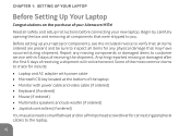
... that were shipped to inspect all safety and setup instructions before connecting your Alienware M17x! Anything reported missing or damaged after the first 5 days of the laptop •• Monitor with power cable and video cable (if ordered) •• Keyboard (if ordered) •• Mouse (if ordered) •• Multimedia speakers and sub-woofer (if ordered) •• Joystick controllers (if ordered) You may have occurred during shipment.
... that were shipped to inspect all safety and setup instructions before connecting your Alienware M17x! Anything reported missing or damaged after the first 5 days of the laptop •• Monitor with power cable and video cable (if ordered) •• Keyboard (if ordered) •• Mouse (if ordered) •• Multimedia speakers and sub-woofer (if ordered) •• Joystick controllers (if ordered) You may have occurred during shipment.

Mobile Manual
Page 28
... while charging a USB device, the device stops charging. Connects to charge USB devices when the computer is powered on the computer to eSATA compatible storage devices (such as external hard drives or optical drives) or USB devices (such as a DVD player, camcorder, or gaming device. The USB Powershare feature allows you turn on /off your video device such as a mouse, keyboard, printer, external drive, or MP3 player). In such cases, turn off or in sleep mode through the BIOS settings. To continue charging...
... while charging a USB device, the device stops charging. Connects to charge USB devices when the computer is powered on the computer to eSATA compatible storage devices (such as external hard drives or optical drives) or USB devices (such as a DVD player, camcorder, or gaming device. The USB Powershare feature allows you turn on /off your video device such as a mouse, keyboard, printer, external drive, or MP3 player). In such cases, turn off or in sleep mode through the BIOS settings. To continue charging...

Mobile Manual
Page 42
... by pressing on your computer. 40 You can connect an external display such as a standalone monitor, an LCD TV, or a projector. CHAPTER 3: USING YOUR LAPTOP Alienware Command Center The Alienware Command Center gives you access to build a library of the connectors on page 33. As Alienware releases new programs, they download directly into the Command Center allowing you to Alienware's exclusive software and is a continuously upgradable control panel.
... by pressing on your computer. 40 You can connect an external display such as a standalone monitor, an LCD TV, or a projector. CHAPTER 3: USING YOUR LAPTOP Alienware Command Center The Alienware Command Center gives you access to build a library of the connectors on page 33. As Alienware releases new programs, they download directly into the Command Center allowing you to Alienware's exclusive software and is a continuously upgradable control panel.

Mobile Manual
Page 59
NOTE: If USB Powershare is enabled, a device connected to enable or disable the USB emulation feature. NOTE: You cannot boot any type of a USB-aware operating system, handles USB devices. Allows you to enable or disable the Intel SpeedStep technology. CHAPTER 3: USING YOUR LAPTOP Advanced Menu Intel SpeedStep Virtualization USB Emulation USB Wake Support Allows you to enable USB devices to wake the computer from standby or to disable the USB wake support feature. USB emulation is off. Allows...
NOTE: If USB Powershare is enabled, a device connected to enable or disable the USB emulation feature. NOTE: You cannot boot any type of a USB-aware operating system, handles USB devices. Allows you to enable or disable the Intel SpeedStep technology. CHAPTER 3: USING YOUR LAPTOP Advanced Menu Intel SpeedStep Virtualization USB Emulation USB Wake Support Allows you to enable USB devices to wake the computer from standby or to disable the USB wake support feature. USB emulation is off. Allows...

Mobile Manual
Page 66
... enable or disable Computrace security feature. Boot Menu Use the up or down arrow keys to the computer at boot. CHAPTER 3: USING YOUR LAPTOP Security Menu Set Service Tag Set Supervisor Password Set User Password Computrace Displays the service tag of the computer when the service tag is absent. You can choose from: •• Hard Drive •• USB Storage •• CD/DVD/BD •• Removal Devices •• Network 64 The user password controls access to change the boot device...
... enable or disable Computrace security feature. Boot Menu Use the up or down arrow keys to the computer at boot. CHAPTER 3: USING YOUR LAPTOP Security Menu Set Service Tag Set Supervisor Password Set User Password Computrace Displays the service tag of the computer when the service tag is absent. You can choose from: •• Hard Drive •• USB Storage •• CD/DVD/BD •• Removal Devices •• Network 64 The user password controls access to change the boot device...

Mobile Manual
Page 73
... the power button to prevent the computer cover from the battery bay before you must remove the battery from being scratched. 2. CHAPTER 4: INSTALLING AND REPLACING COMPONENTS CAUTION: To avoid damaging the computer, perform the following steps before you service the laptop. 6. CAUTION: To disconnect a network cable, first unplug the cable from your computer and all telephone or network cables from the Media Card Reader. 5. Press and eject any installed cards...
... the power button to prevent the computer cover from the battery bay before you must remove the battery from being scratched. 2. CHAPTER 4: INSTALLING AND REPLACING COMPONENTS CAUTION: To avoid damaging the computer, perform the following steps before you service the laptop. 6. CAUTION: To disconnect a network cable, first unplug the cable from your computer and all telephone or network cables from the Media Card Reader. 5. Press and eject any installed cards...
Mobile Manual
Page 77
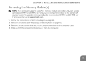
... compartment door to four memory module connectors. Follow the instructions in connectors DIMM 3 and DIMM 4, see "Replacing the Battery Pack" on page 68. 2. To upgrade memory module(s) in "Before You Begin" on page 72). 3. CHAPTER 4: INSTALLING AND REPLACING COMPONENTS Removing the Memory Module(s) NOTE: Your computer supports up to the computer base. 4. You can access connectors DIMM 1 and DIMM 2 by removing the compartment door at support.dell.com. 1.
... compartment door to four memory module connectors. Follow the instructions in connectors DIMM 3 and DIMM 4, see "Replacing the Battery Pack" on page 68. 2. To upgrade memory module(s) in "Before You Begin" on page 72). 3. CHAPTER 4: INSTALLING AND REPLACING COMPONENTS Removing the Memory Module(s) NOTE: Your computer supports up to the computer base. 4. You can access connectors DIMM 1 and DIMM 2 by removing the compartment door at support.dell.com. 1.

Service Manual (English Only)
Page 4
Replacing the Hard Drive(s 22 6 Memory Module(s 25 Removing the Memory Module(s 25 Replacing the Memory Module(s 27 7 Graphics-Card Heat Sink Fan 31 Removing the Graphics-Card Heat Sink Fan 31 Replacing the Graphics-Card Heat Sink Fan 32 8 Graphics-Card Assembly 35 Removing the Graphics-Card Assembly 35 Replacing the Graphics-Card Assembly 36 9 Processor Heat-Sink Fan 37 Removing the Processor Heat-Sink Fan 37 Replacing the Processor Heat-Sink Fan 38 10 Processor Heat-Sink 41 Removing the Processor Heat-Sink 41 Replacing the Processor Heat-Sink 42 4 Contents
Replacing the Hard Drive(s 22 6 Memory Module(s 25 Removing the Memory Module(s 25 Replacing the Memory Module(s 27 7 Graphics-Card Heat Sink Fan 31 Removing the Graphics-Card Heat Sink Fan 31 Replacing the Graphics-Card Heat Sink Fan 32 8 Graphics-Card Assembly 35 Removing the Graphics-Card Assembly 35 Replacing the Graphics-Card Assembly 36 9 Processor Heat-Sink Fan 37 Removing the Processor Heat-Sink Fan 37 Replacing the Processor Heat-Sink Fan 38 10 Processor Heat-Sink 41 Removing the Processor Heat-Sink 41 Replacing the Processor Heat-Sink 42 4 Contents

Service Manual (English Only)
Page 5
11 Processor Module 45 Removing the Processor Module 45 Replacing the Processor Module 46 12 Center Control Cover 49 Removing the Center Control Cover 49 Replacing the Center Control Cover 52 13 Keyboard 55 Removing the Keyboard 55 Replacing the Keyboard 57 14 Wireless Mini-Card 59 Removing the Mini-Card 59 Replacing the Mini-Card 61 15 WirelessHD Card (Optional 63 Removing the WirelessHD Card 63 Replacing the WirelessHD Card 64 16 Power Button Board 67 Removing the Power Button Board 67 Contents 5
11 Processor Module 45 Removing the Processor Module 45 Replacing the Processor Module 46 12 Center Control Cover 49 Removing the Center Control Cover 49 Replacing the Center Control Cover 52 13 Keyboard 55 Removing the Keyboard 55 Replacing the Keyboard 57 14 Wireless Mini-Card 59 Removing the Mini-Card 59 Replacing the Mini-Card 61 15 WirelessHD Card (Optional 63 Removing the WirelessHD Card 63 Replacing the WirelessHD Card 64 16 Power Button Board 67 Removing the Power Button Board 67 Contents 5

Service Manual (English Only)
Page 22
... shipping the hard drive. 3 Connect the interposer to the hard-drive bracket. 6 Align the connector on the hard drive with the connector on the system board and press the hard drive until it in protective antistatic packaging (see "Protecting Against Electrostatic Discharge" in the safety instructions that secure the hard drive to the hard drive. 4 Place the hard drive in "Before You Begin" on page 9. 2 Remove the new drive from...
... shipping the hard drive. 3 Connect the interposer to the hard-drive bracket. 6 Align the connector on the hard drive with the connector on the system board and press the hard drive until it in protective antistatic packaging (see "Protecting Against Electrostatic Discharge" in the safety instructions that secure the hard drive to the hard drive. 4 Place the hard drive in "Before You Begin" on page 9. 2 Remove the new drive from...
Service Manual (English Only)
Page 25
... your computer supports only memory module connectors DIMM 1 and DIMM 2. CAUTION: To help prevent damage to servicing that shipped with your computer. CAUTION: Only a certified service technician should perform repairs on the system board. NOTE: Memory modules purchased from Dell or Alienware are covered under your computer. You can access connectors DIMM 3 and DIMM 4 by installing memory modules on your computer warranty. 6 Memory Module(s) WARNING: Before working inside your...
... your computer supports only memory module connectors DIMM 1 and DIMM 2. CAUTION: To help prevent damage to servicing that shipped with your computer. CAUTION: Only a certified service technician should perform repairs on the system board. NOTE: Memory modules purchased from Dell or Alienware are covered under your computer. You can access connectors DIMM 3 and DIMM 4 by installing memory modules on your computer warranty. 6 Memory Module(s) WARNING: Before working inside your...

Service Manual (English Only)
Page 27
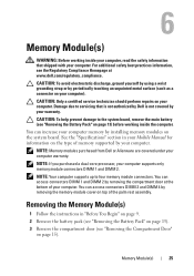
... hear the click, remove the memory module and reinstall it clicks into the connector at a 45-degree angle, and press the memory module down until it . Memory Module(s) 27 NOTE: If the memory module is not installed properly, the computer may not boot. 1 3 2 1 memory-module connector 3 memory module 2 securing clips (2) 7 Remove the memory module from the memory-module connector. Replacing the Memory Module(s) 1 Follow the instructions in the memory-module connector. 3 Slide the memory module firmly into place.
... hear the click, remove the memory module and reinstall it clicks into the connector at a 45-degree angle, and press the memory module down until it . Memory Module(s) 27 NOTE: If the memory module is not installed properly, the computer may not boot. 1 3 2 1 memory-module connector 3 memory module 2 securing clips (2) 7 Remove the memory module from the memory-module connector. Replacing the Memory Module(s) 1 Follow the instructions in the memory-module connector. 3 Slide the memory module firmly into place.

Service Manual (English Only)
Page 49
... computer. CAUTION: Only a certified service technician should perform repairs on page 13) before working inside the computer. For additional safety best practices information, see "Removing the Battery Pack" on your computer. CAUTION: To help prevent damage to the system board, remove the main battery (see the Regulatory Compliance Homepage at www.dell.com/regulatory_compliance. Center Control Cover 49 CAUTION: To avoid...
... computer. CAUTION: Only a certified service technician should perform repairs on page 13) before working inside the computer. For additional safety best practices information, see "Removing the Battery Pack" on your computer. CAUTION: To help prevent damage to the system board, remove the main battery (see the Regulatory Compliance Homepage at www.dell.com/regulatory_compliance. Center Control Cover 49 CAUTION: To avoid...
Service Manual (English Only)
Page 62
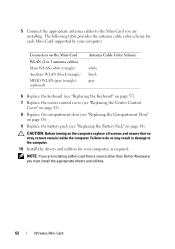
... the Mini-Card you must install the appropriate drivers and utilities. 62 Wireless Mini-Card NOTE: If you are installing a Mini-card from a source other than Dell or Alienware, you are installing. CAUTION: Before turning on page 14). The following table provides the antenna cable color scheme for your computer. 5 Connect the appropriate antenna cables to the computer. 10 Install the drivers and utilities for each Mini-Card supported by...
... the Mini-Card you must install the appropriate drivers and utilities. 62 Wireless Mini-Card NOTE: If you are installing a Mini-card from a source other than Dell or Alienware, you are installing. CAUTION: Before turning on page 14). The following table provides the antenna cable color scheme for your computer. 5 Connect the appropriate antenna cables to the computer. 10 Install the drivers and utilities for each Mini-Card supported by...

Service Manual (English Only)
Page 64
... pressure to slide the card into the slot on the system board and replace the screw that secures the wirelessHD card to the system board. 5 Connect the wirelessHD card cable to ensure correct insertion. CAUTION: The connectors are keyed to the connector on the wirelessHD card. 6 Replace the keyboard (see "Replacing the Keyboard" on page 9. 2 Remove the new wirelessHD card from its packaging. If you use excessive force, you...
... pressure to slide the card into the slot on the system board and replace the screw that secures the wirelessHD card to the system board. 5 Connect the wirelessHD card cable to ensure correct insertion. CAUTION: The connectors are keyed to the connector on the wirelessHD card. 6 Replace the keyboard (see "Replacing the Keyboard" on page 9. 2 Remove the new wirelessHD card from its packaging. If you use excessive force, you...

Service Manual (English Only)
Page 96
... control cover (see "Removing the Center Control Cover" on page 49). 14 Remove the keyboard (see "Removing the Keyboard" on page 55). 15 Remove the Mini-Card (see "Removing the Mini-Card" on page 59). 16 Remove the power button board (see "Removing the Power Button Board" on page 67). 17 Remove the display assembly (see "Removing the Display Assembly" on page 71). 18 Remove the wirelessHD card (see "Removing the WirelessHD Card" on page 63). 19 Remove the status light board...
... control cover (see "Removing the Center Control Cover" on page 49). 14 Remove the keyboard (see "Removing the Keyboard" on page 55). 15 Remove the Mini-Card (see "Removing the Mini-Card" on page 59). 16 Remove the power button board (see "Removing the Power Button Board" on page 67). 17 Remove the display assembly (see "Removing the Display Assembly" on page 71). 18 Remove the wirelessHD card (see "Removing the WirelessHD Card" on page 63). 19 Remove the status light board...

Service Manual (English Only)
Page 103
... reduce battery life. NOTE: If USB Powershare is off or in the absence of USB device (floppy, hard drive, or memory key) when this feature may not wake the computer. Disabling this option is enabled, a device connected to enable or disable the USB emulation feature. This feature defines how the BIOS, in standby mode. • AC Only: Charge USB devices when connected to AC adapter only. • AC and Battery: Charge USB devices when connected to disable the USB wake support...
... reduce battery life. NOTE: If USB Powershare is off or in the absence of USB device (floppy, hard drive, or memory key) when this feature may not wake the computer. Disabling this option is enabled, a device connected to enable or disable the USB emulation feature. This feature defines how the BIOS, in standby mode. • AC Only: Charge USB devices when connected to AC adapter only. • AC and Battery: Charge USB devices when connected to disable the USB wake support...

Service Manual (English Only)
Page 105
... feature is disabled. • Enabled: Displays additional overclocking options. Bus Clock Current Frequency Displays the current bus clock frequency. Allows you to set the turbo mode power limit 2value in increments of 10KHz. Allows you use AC adapters that are not supported by your computer. • Enabled: BIOS will detect unsupported AC adapters and display an error on the screen. Adapter Warnings Charger Behavior Advanced Menu-Performance Options Overclocking Feature...
... feature is disabled. • Enabled: Displays additional overclocking options. Bus Clock Current Frequency Displays the current bus clock frequency. Allows you to set the turbo mode power limit 2value in increments of 10KHz. Allows you use AC adapters that are not supported by your computer. • Enabled: BIOS will detect unsupported AC adapters and display an error on the screen. Adapter Warnings Charger Behavior Advanced Menu-Performance Options Overclocking Feature...

Service Manual (English Only)
Page 107
... Set Service Tag Displays the service tag of the computer when the service tag is clear or set. Set User Password Allows you to remain in System Setup and save your changes to enable or disable Computrace security feature. Boot Menu Use the up or down arrow keys to the system setup utility. Exit Discarding Changes Allows you to exit System Setup and load previous values from : • Hard Drive • USB Storage • CD/DVD...
... Set Service Tag Displays the service tag of the computer when the service tag is clear or set. Set User Password Allows you to remain in System Setup and save your changes to enable or disable Computrace security feature. Boot Menu Use the up or down arrow keys to the system setup utility. Exit Discarding Changes Allows you to exit System Setup and load previous values from : • Hard Drive • USB Storage • CD/DVD...


