
Service Manual
Page 4
...-requisites...42 Removing the hard-drive cage 43 Prerequisites...43 Procedure...43 Replacing the hard-drive cage 44 Procedure...44 Post-requisites...44 Removing the power-supply unit 45 Prerequisites...45 Procedure...45 Replacing the power-supply unit 49 Procedure...49 Post-requisites...52 Removing the processor-cooling assembly 53 Prerequisites...53 Procedure...53 4
...-requisites...42 Removing the hard-drive cage 43 Prerequisites...43 Procedure...43 Replacing the hard-drive cage 44 Procedure...44 Post-requisites...44 Removing the power-supply unit 45 Prerequisites...45 Procedure...45 Replacing the power-supply unit 49 Procedure...49 Post-requisites...52 Removing the processor-cooling assembly 53 Prerequisites...53 Procedure...53 4
Service Manual
Page 13
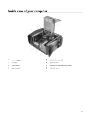
Inside view of your computer 1 power-supply unit 3 top cover 5 system board 7 graphics card 2 optical-drive assembly 4 top-chassis fan 6 processor fan and heat-sink assembly 8 right-side cover 13
Inside view of your computer 1 power-supply unit 3 top cover 5 system board 7 graphics card 2 optical-drive assembly 4 top-chassis fan 6 processor fan and heat-sink assembly 8 right-side cover 13
Service Manual
Page 15
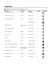
... ordered. Component 3.5-inch hard-drive cage Secured to Chassis Screw type #6-32 X 1/4'' Quantity 2 Screw image 2.5-inch hard-drive cage Chassis #6-32 X 1/4'' 4 Power-supply unit hinge Chassis #6-32 X 1/4'' 6 #6-32 X 1/4'' BLK 3 Power-supply unit Power-supply unit bracket Power-supply unit #6-32 X 1/4'' 4 hinge #6-32 X 1/4'' 2 Optical-drive assembly Chassis #6-32 X 1/4'' 2 System board Chassis #6-32 X 1/4'' 8 Top cover Chassis #6-32 X 1/4'' 2 Top I/O assembly Chassis...
... ordered. Component 3.5-inch hard-drive cage Secured to Chassis Screw type #6-32 X 1/4'' Quantity 2 Screw image 2.5-inch hard-drive cage Chassis #6-32 X 1/4'' 4 Power-supply unit hinge Chassis #6-32 X 1/4'' 6 #6-32 X 1/4'' BLK 3 Power-supply unit Power-supply unit bracket Power-supply unit #6-32 X 1/4'' 4 hinge #6-32 X 1/4'' 2 Optical-drive assembly Chassis #6-32 X 1/4'' 2 System board Chassis #6-32 X 1/4'' 8 Top cover Chassis #6-32 X 1/4'' 2 Top I/O assembly Chassis...
Service Manual
Page 45
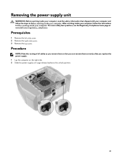
... safety best practices, see the Regulatory Compliance home page at www.dell.com/regulatory_compliance. Removing the power-supply unit WARNING: Before working inside your computer, read the safety information that you replace the power supply. 1 Lay the computer on the right side. 2 Slide the power-supply unit cage release latches to the unlock position. 45 After working...
... safety best practices, see the Regulatory Compliance home page at www.dell.com/regulatory_compliance. Removing the power-supply unit WARNING: Before working inside your computer, read the safety information that you replace the power supply. 1 Lay the computer on the right side. 2 Slide the power-supply unit cage release latches to the unlock position. 45 After working...

Service Manual
Page 46
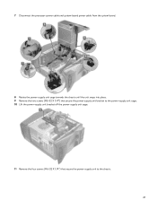
3 Lift the power-supply unit cage while pressing and holding the graphics-card bracket. 4 Rotate the power-supply unit cage away from the chassis. 5 Press the releasing clip on the power-cable connectors and disconnect the power cables from the graphics card. 6 Disconnect the power cables from the optical drive and hard drives. 46
3 Lift the power-supply unit cage while pressing and holding the graphics-card bracket. 4 Rotate the power-supply unit cage away from the chassis. 5 Press the releasing clip on the power-cable connectors and disconnect the power cables from the graphics card. 6 Disconnect the power cables from the optical drive and hard drives. 46
Service Manual
Page 47
7 Disconnect the processor-power cable and system-board power cable from the system board. 8 Rotate the power-supply unit cage towards the chassis until the unit snaps into place. 9 Remove the two screws (#6-32 X 1/4") that secure the power-supply unit bracket to the power-supply unit cage. 10 Lift the power-supply unit bracket off the power-supply unit cage. 11 Remove the four screws (#6-32 X 1/4") that secure the power-supply unit to the chassis. 47
7 Disconnect the processor-power cable and system-board power cable from the system board. 8 Rotate the power-supply unit cage towards the chassis until the unit snaps into place. 9 Remove the two screws (#6-32 X 1/4") that secure the power-supply unit bracket to the power-supply unit cage. 10 Lift the power-supply unit bracket off the power-supply unit cage. 11 Remove the four screws (#6-32 X 1/4") that secure the power-supply unit to the chassis. 47
Service Manual
Page 48
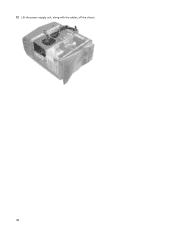
12 Lift the power-supply unit, along with the cables, off the chassis. 48
12 Lift the power-supply unit, along with the cables, off the chassis. 48
Service Manual
Page 49
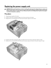
... screw holes on the chassis. 3 Replace the four screws (#6-32 X 1/4") that secure the power-supply unit bracket to the power-supply unit cage. 49 For more safety best practices, see the Regulatory Compliance home page at www.dell.com/regulatory_compliance. Replacing the power-supply unit WARNING: Before working inside your computer, read the safety information that shipped...
... screw holes on the chassis. 3 Replace the four screws (#6-32 X 1/4") that secure the power-supply unit bracket to the power-supply unit cage. 49 For more safety best practices, see the Regulatory Compliance home page at www.dell.com/regulatory_compliance. Replacing the power-supply unit WARNING: Before working inside your computer, read the safety information that shipped...
Service Manual
Page 50
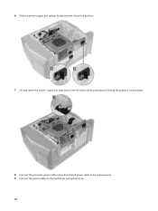
6 Slide the power-supply unit release latches towards the unlock position. 7 Lift and rotate the power-supply unit cage away from the chassis while pressing and holding the graphics-card bracket. 8 Connect the processor-power cable and system-board power cable to the system board. 9 Connect the power cables to the hard drives and optical drive. 50
6 Slide the power-supply unit release latches towards the unlock position. 7 Lift and rotate the power-supply unit cage away from the chassis while pressing and holding the graphics-card bracket. 8 Connect the processor-power cable and system-board power cable to the system board. 9 Connect the power cables to the hard drives and optical drive. 50
Service Manual
Page 51
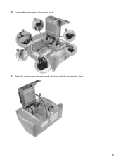
10 Connect the power cables to the graphics card. 11 Rotate the power-supply unit cage towards the chassis until the unit snaps into place. 51
10 Connect the power cables to the graphics card. 11 Rotate the power-supply unit cage towards the chassis until the unit snaps into place. 51
Service Manual
Page 52
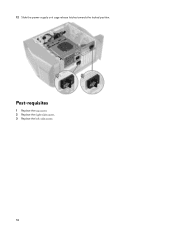
Post-requisites 1 Replace the top cover. 2 Replace the right-side cover. 3 Replace the left-side cover. 52 12 Slide the power-supply unit cage release latches towards the locked position.
Post-requisites 1 Replace the top cover. 2 Replace the right-side cover. 3 Replace the left-side cover. 52 12 Slide the power-supply unit cage release latches towards the locked position.
Service Manual
Page 53
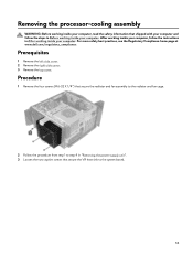
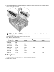
... the radiator and fan assembly to the radiator and fan cage. 2 Follow the procedure from step 1 to step 4 in "Removing the power-supply unit". 3 Loosen the two captive screws that shipped with your computer and follow the instructions in Before working inside your computer. For more safety... best practices, see the Regulatory Compliance home page at www.dell.com/regulatory_compliance. Prerequisites 1 Remove the left-side cover. 2 Remove the right-side cover. 3 Remove the top cover. After working ...
... the radiator and fan assembly to the radiator and fan cage. 2 Follow the procedure from step 1 to step 4 in "Removing the power-supply unit". 3 Loosen the two captive screws that shipped with your computer and follow the instructions in Before working inside your computer. For more safety... best practices, see the Regulatory Compliance home page at www.dell.com/regulatory_compliance. Prerequisites 1 Remove the left-side cover. 2 Remove the right-side cover. 3 Remove the top cover. After working ...

Service Manual
Page 56
6 Tighten the two captive screws that secure the VR heat sink to the system board. 7 Follow the procedure from step 10 to step 11 in "Replacing the power-supply unit". 8 Replace the four screws (#6-32 X 1/4") that secure the radiator and fan assembly to the chassis. Post-requisites 1 Replace the top cover. 2 Replace the right-side cover. 3 Replace the left-side cover. 56
6 Tighten the two captive screws that secure the VR heat sink to the system board. 7 Follow the procedure from step 10 to step 11 in "Replacing the power-supply unit". 8 Replace the four screws (#6-32 X 1/4") that secure the radiator and fan assembly to the chassis. Post-requisites 1 Replace the top cover. 2 Replace the right-side cover. 3 Replace the left-side cover. 56

Service Manual
Page 57
...-cell battery pops up. 2 Lift the coin-cell battery out of its socket. 57 After working inside your computer, follow the steps in "Removing the power-supply unit". For more safety best practices, see the Regulatory Compliance home page at www...
...-cell battery pops up. 2 Lift the coin-cell battery out of its socket. 57 After working inside your computer, follow the steps in "Removing the power-supply unit". For more safety best practices, see the Regulatory Compliance home page at www...

Service Manual
Page 58
... (CR2032) into the battery socket with your computer and follow the instructions in "Replacing the power-supply unit". 2 Replace the left-side cover. 58 For more safety best practices, see the Regulatory Compliance home page at www.dell.com/regulatory_compliance. Post-requisites 1 Follow the procedure from step 10 to step 11 in After...
... (CR2032) into the battery socket with your computer and follow the instructions in "Replacing the power-supply unit". 2 Replace the left-side cover. 58 For more safety best practices, see the Regulatory Compliance home page at www.dell.com/regulatory_compliance. Post-requisites 1 Follow the procedure from step 10 to step 11 in After...

Service Manual
Page 59
... For more safety best practices, see "System-board components". 2 Push the securing clips away from step 1 to step 4 in "Removing the power-supply unit". Prerequisites 1 Remove the left-side cover. 2 Follow the procedure from the memory module. 3 Grasp the memory module near the securing clip... gently ease the memory module out of the memory-module slot. For more information, see the Regulatory Compliance home page at www.dell.com/regulatory_compliance. After working inside your computer, follow the steps in Before working inside your computer. NOTE: Repeat step 2 to step...
... For more safety best practices, see "System-board components". 2 Push the securing clips away from step 1 to step 4 in "Removing the power-supply unit". Prerequisites 1 Remove the left-side cover. 2 Follow the procedure from the memory module. 3 Grasp the memory module near the securing clip... gently ease the memory module out of the memory-module slot. For more information, see the Regulatory Compliance home page at www.dell.com/regulatory_compliance. After working inside your computer, follow the steps in Before working inside your computer. NOTE: Repeat step 2 to step...
Service Manual
Page 61
... module into the memory-module slot and press the memory module down until it snaps into position and the securing clips lock in "Replacing the power-supply unit". 2 Replace the left-side cover. 61 NOTE: Use slots XMM1 and XMM2 if you need to step 11 in place. For more information, see...
... module into the memory-module slot and press the memory module down until it snaps into position and the securing clips lock in "Replacing the power-supply unit". 2 Replace the left-side cover. 61 NOTE: Use slots XMM1 and XMM2 if you need to step 11 in place. For more information, see...
Service Manual
Page 62
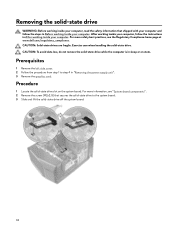
... working inside your computer. For more information, see the Regulatory Compliance home page at www.dell.com/regulatory_compliance. CAUTION: To avoid data loss, do not remove the solid-state drive while the computer is in "Removing the power-supply unit". 3 Remove the graphics card. Prerequisites 1 Remove the left-side cover. 2 Follow the procedure...
... working inside your computer. For more information, see the Regulatory Compliance home page at www.dell.com/regulatory_compliance. CAUTION: To avoid data loss, do not remove the solid-state drive while the computer is in "Removing the power-supply unit". 3 Remove the graphics card. Prerequisites 1 Remove the left-side cover. 2 Follow the procedure...

Service Manual
Page 63
... system board. CAUTION: Solid-state drives are fragile. Procedure 1 Align the notch on the solid-state drive slot. 2 Insert the solid-state drive at www.dell.com/regulatory_compliance. Exercise care when handling the solid-state drive. Replacing the solid-state drive WARNING: Before working inside your computer, read the safety information... and replace the screw (M2x2.5) that shipped with the tab on the solid-state drive with your computer and follow the instructions in "Replacing the power-supply unit". 3 Replace the left-side cover. 63
... system board. CAUTION: Solid-state drives are fragile. Procedure 1 Align the notch on the solid-state drive slot. 2 Insert the solid-state drive at www.dell.com/regulatory_compliance. Exercise care when handling the solid-state drive. Replacing the solid-state drive WARNING: Before working inside your computer, read the safety information... and replace the screw (M2x2.5) that shipped with the tab on the solid-state drive with your computer and follow the instructions in "Replacing the power-supply unit". 3 Replace the left-side cover. 63
Service Manual
Page 64
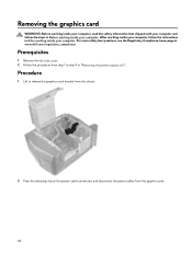
For more safety best practices, see the Regulatory Compliance home page at www.dell.com/regulatory_compliance. Prerequisites 1 Remove the left-side cover. 2 Follow the procedure from the graphics card. 64 After working inside your computer, follow the... Procedure 1 Lift to release the graphics-card bracket from the chassis. 2 Press the releasing clip on the power-cable connectors and disconnect the power cables from step 1 to step 4 in "Removing the power-supply unit". Removing the graphics card WARNING: Before working inside your computer, read the safety information that shipped with ...
For more safety best practices, see the Regulatory Compliance home page at www.dell.com/regulatory_compliance. Prerequisites 1 Remove the left-side cover. 2 Follow the procedure from the graphics card. 64 After working inside your computer, follow the... Procedure 1 Lift to release the graphics-card bracket from the chassis. 2 Press the releasing clip on the power-cable connectors and disconnect the power cables from step 1 to step 4 in "Removing the power-supply unit". Removing the graphics card WARNING: Before working inside your computer, read the safety information that shipped with ...


