Service Manual
Page 21
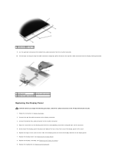
... the display panel with the corresponding screw holes and guide pins on each side of the display panel) to secure the display brackets to the inverter connector. 4. Replace the display assembly (see Replacing the Display Bezel). 8. Connect the top flex-cable connector to the cover. 6. Replace the display bezel (see Replacing...
... the display panel with the corresponding screw holes and guide pins on each side of the display panel) to secure the display brackets to the inverter connector. 4. Replace the display assembly (see Replacing the Display Bezel). 8. Connect the top flex-cable connector to the cover. 6. Replace the display bezel (see Replacing...


