Product Manual
Page 7
Software User Manual 12/10/09 D-Link Unified Access System SNTP Server Configuration ...98 SNTP Server Status...99 SNTP Global Status ...100 Time Zone Configuration ...101 Summer Time Configuration ...103 Summer Time ... ...123 Defining SNMP Parameters ...124 SNMP v1 and v2 ...124 SNMP v3...124 SNMP Community Configuration ...125 Trap Receiver Configuration ...126 Trap Flags...127 Supported MIBs ...128 Viewing System Statistics ...129 34CSFP6XXUWS-SWUM100-D7 Page 7
Software User Manual 12/10/09 D-Link Unified Access System SNTP Server Configuration ...98 SNTP Server Status...99 SNTP Global Status ...100 Time Zone Configuration ...101 Summer Time Configuration ...103 Summer Time ... ...123 Defining SNMP Parameters ...124 SNMP v1 and v2 ...124 SNMP v3...124 SNMP Community Configuration ...125 Trap Receiver Configuration ...126 Trap Flags...127 Supported MIBs ...128 Viewing System Statistics ...129 34CSFP6XXUWS-SWUM100-D7 Page 7
Product Manual
Page 22
D-Link Unified Access System Software User Manual 12/10/09 Figure 34: Event Log...88 Figure 35: Host Configuration ...89 Figure 36: Host Configuration with Logging ...: sFlow Sampler Configuration...124 Figure 64: SNMP Community Configuration 125 Figure 65: Trap Receiver Configuration ...127 Figure 66: Trap Flags Configuration ...128 Figure 67: Supported MIBs ...129 Figure 68: Switch Detailed ...130 Page 22 Document 34CSFP6XXUWS-SWUM100-D7
D-Link Unified Access System Software User Manual 12/10/09 Figure 34: Event Log...88 Figure 35: Host Configuration ...89 Figure 36: Host Configuration with Logging ...: sFlow Sampler Configuration...124 Figure 64: SNMP Community Configuration 125 Figure 65: Trap Receiver Configuration ...127 Figure 66: Trap Flags Configuration ...128 Figure 67: Supported MIBs ...129 Figure 68: Switch Detailed ...130 Page 22 Document 34CSFP6XXUWS-SWUM100-D7

Product Manual
Page 34
D-Link Unified Access System Software User Manual 12/10/09 Table 34: SNTP Server Configuration Fields 98 Table 35: SNTP Server Status Fields ...99 Table 36: ... Configuration ...124 Table 54: Community Configuration Fields 126 Table 55: Trap Receiver Configuration Fields 127 Table 56: Trap Flags Configuration Fields ...128 Table 57: Supported MIBs Fields...129 Table 58: Switch Detailed Statistics Fields 130 Table 59: Switch Summary Fields...132 Table 60: Port Fields ...133 Table 61: Port Summary Statistics...
D-Link Unified Access System Software User Manual 12/10/09 Table 34: SNTP Server Configuration Fields 98 Table 35: SNTP Server Status Fields ...99 Table 36: ... Configuration ...124 Table 54: Community Configuration Fields 126 Table 55: Trap Receiver Configuration Fields 127 Table 56: Trap Flags Configuration Fields ...128 Table 57: Supported MIBs Fields...129 Table 58: Switch Detailed Statistics Fields 130 Table 59: Switch Summary Fields...132 Table 60: Port Fields ...133 Table 61: Port Summary Statistics...
Product Manual
Page 53
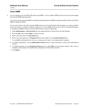
You can configure SNMP groups and users that can manage the D-Link DWS-4026 switch using the SNMPv3 protocol, but for the encryption scheme. ...1 Select Administration > User Accounts from the hierarchical tree on the left side of eight or more alphanumeric characters in the D-Link CLI Command Reference. Any user can connect to create a new user. 3 Enter a new user name in the User ... a new user profile. To configure an SNMPv3 profile by default. D-Link uses both standard public MIBs for standard functionality and private MIBs that support additional switch functionality.
You can configure SNMP groups and users that can manage the D-Link DWS-4026 switch using the SNMPv3 protocol, but for the encryption scheme. ...1 Select Administration > User Accounts from the hierarchical tree on the left side of eight or more alphanumeric characters in the D-Link CLI Command Reference. Any user can connect to create a new user. 3 Enter a new user name in the User ... a new user profile. To configure an SNMPv3 profile by default. D-Link uses both standard public MIBs for standard functionality and private MIBs that support additional switch functionality.
Product Manual
Page 59
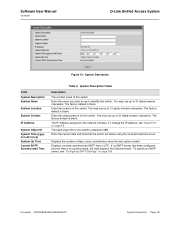
... use to 31 alpha-numeric characters. The factory default is not synchronized, this switch. Enter the contact person for the switch's enterprise MIB. Software User Manual 12/10/09 D-Link Unified Access System Figure 10: System Description Field System Description System Name System Location System Contact IP Address System Object ID System...
... use to 31 alpha-numeric characters. The factory default is not synchronized, this switch. Enter the contact person for the switch's enterprise MIB. Software User Manual 12/10/09 D-Link Unified Access System Figure 10: System Description Field System Description System Name System Location System Contact IP Address System Object ID System...

Product Manual
Page 83
...and displays the entries based on the filter you select, which can be one of entries to search the forwarding database. The status of the MIB interface table entry associated with interface 0.1. • Self: The MAC address of one of the following procedures to display. Software User Manual ...12/10/09 D-Link Unified Access System SEARCH Use the Search page to search for which the MAC address can be reached. This field allows you select All, ...
...and displays the entries based on the filter you select, which can be one of entries to search the forwarding database. The status of the MIB interface table entry associated with interface 0.1. • Self: The MAC address of one of the following procedures to display. Software User Manual ...12/10/09 D-Link Unified Access System SEARCH Use the Search page to search for which the MAC address can be reached. This field allows you select All, ...

Product Manual
Page 115
...the source port, that are both received and transmitted, can be up to 64 characters in length. Software User Manual 12/10/09 D-Link Unified Access System PORT DESCRIPTION Use the Port Description page to configure a human-readable description of the specified interface. You have an associated description... If you change a port description, click Submit to apply the change to the system. • Click Refresh to the port when the MIB object type PortList is configured as source ports and one switch port is used to manage in the navigation tree. Figure 55: Port Description ...
...the source port, that are both received and transmitted, can be up to 64 characters in length. Software User Manual 12/10/09 D-Link Unified Access System PORT DESCRIPTION Use the Port Description page to configure a human-readable description of the specified interface. You have an associated description... If you change a port description, click Submit to apply the change to the system. • Click Refresh to the port when the MIB object type PortList is configured as source ports and one switch port is used to manage in the navigation tree. Figure 55: Port Description ...
Product Manual
Page 120
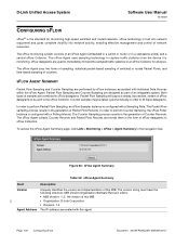
... the sFlow Agent Summary page, click LAN > Monitoring > sFlow > Agent Summary in the generation of Packet Flow Records. D-Link Unified Access System Software User Manual 12/10/09 CONFIGURING SFLOW sFlow® is built into network equipment and gives complete visibility ... 60: sFlow Agent Summary Table 50: sFlow Agent Summary Field Description Version Uniquely identifies the version and implementation of this MIB. • Organization: D-Link Corporation • Revision: 1.0 Agent Address The IP address associated with individual Data Sources within the sFlow Agent. The ...
... the sFlow Agent Summary page, click LAN > Monitoring > sFlow > Agent Summary in the generation of Packet Flow Records. D-Link Unified Access System Software User Manual 12/10/09 CONFIGURING SFLOW sFlow® is built into network equipment and gives complete visibility ... 60: sFlow Agent Summary Table 50: sFlow Agent Summary Field Description Version Uniquely identifies the version and implementation of this MIB. • Organization: D-Link Corporation • Revision: 1.0 Agent Address The IP address associated with individual Data Sources within the sFlow Agent. The ...
Product Manual
Page 124
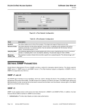
... all samplers associated with the receiver will support Physical ports only. SNMPv3 is supported only in the Management Information Base (MIB). The MIB presents the variables controlled by access strings. Page 124 Defining SNMP Parameters Document 34CSFP6XXUWS-SWUM100-D7 If set to zero, ...sFlow Receiver for this sFlow sampler. The Web interfaces supports configuration of bytes that should be copied from this sFlow sampler. D-Link Unified Access System Software User Manual 12/10/09 Figure 63: sFlow Sampler Configuration Table 53: sFlow Sampler Configuration Field Description...
... all samplers associated with the receiver will support Physical ports only. SNMPv3 is supported only in the Management Information Base (MIB). The MIB presents the variables controlled by access strings. Page 124 Defining SNMP Parameters Document 34CSFP6XXUWS-SWUM100-D7 If set to zero, ...sFlow Receiver for this sFlow sampler. The Web interfaces supports configuration of bytes that should be copied from this sFlow sampler. D-Link Unified Access System Software User Manual 12/10/09 Figure 63: sFlow Sampler Configuration Table 53: sFlow Sampler Configuration Field Description...
Product Manual
Page 126
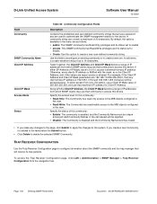
... Use this community: • Read-Only: The Community has read only access to the MIB objects configured in the view. • Read-Write: The Community has read/modify access to the MIB objects configured in the menu are as a password and are used to authenticate the SNMP management... page, click LAN > Administration > SNMP Manager > Trap Receiver Configuration from which SNMP clients may use that community to access this device. D-Link Unified Access System Software User Manual 12/10/09 Field Community SNMP Community Name Client IP Address Client IP Mask Access Mode Status Table 54...
... Use this community: • Read-Only: The Community has read only access to the MIB objects configured in the view. • Read-Write: The Community has read/modify access to the MIB objects configured in the menu are as a password and are used to authenticate the SNMP management... page, click LAN > Administration > SNMP Manager > Trap Receiver Configuration from which SNMP clients may use that community to access this device. D-Link Unified Access System Software User Manual 12/10/09 Field Community SNMP Community Name Client IP Address Client IP Mask Access Mode Status Table 54...
Product Manual
Page 128
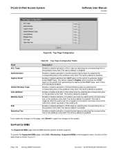
...line on the pulldown entry field. The factory default is enabled. The factory default is shown Figure 67. A portion of link status traps by selecting the corresponding line on the switch to the system. Enable or disable activation of the web screen is enabled.... SUPPORTED MIBS The Supported MIBs page lists the MIBs that the system currently supports. Page 128 Defining SNMP Parameters Document 34CSFP6XXUWS-SWUM100-D7 To access the Supported MIBs page, click LAN > Monitoring > Supported MIBs in the navigation menu. The factory default is...
...line on the pulldown entry field. The factory default is enabled. The factory default is shown Figure 67. A portion of link status traps by selecting the corresponding line on the switch to the system. Enable or disable activation of the web screen is enabled.... SUPPORTED MIBS The Supported MIBs page lists the MIBs that the system currently supports. Page 128 Defining SNMP Parameters Document 34CSFP6XXUWS-SWUM100-D7 To access the Supported MIBs page, click LAN > Monitoring > Supported MIBs in the navigation menu. The factory default is...
Product Manual
Page 129
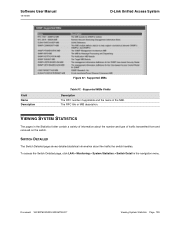
Software User Manual 12/10/09 D-Link Unified Access System Field Name Description Figure 67: Supported MIBs Table 57: Supported MIBs Fields Description The RFC number if applicable and the name of traffic transmitted from and received on the switch. To access the Switch Detailed page, ... of information about the traffic the switch handles. SWITCH DETAILED The Switch Detailed page shows detailed statistical information about the number and type of the MIB. Document 34CSFP6XXUWS-SWUM100-D7 Viewing System Statistics Page 129 The RFC title or...
Software User Manual 12/10/09 D-Link Unified Access System Field Name Description Figure 67: Supported MIBs Table 57: Supported MIBs Fields Description The RFC number if applicable and the name of traffic transmitted from and received on the switch. To access the Switch Detailed page, ... of information about the traffic the switch handles. SWITCH DETAILED The Switch Detailed page shows detailed statistical information about the number and type of the MIB. Document 34CSFP6XXUWS-SWUM100-D7 Viewing System Statistics Page 129 The RFC title or...

Product Manual
Page 327
Classes are active. Figure 229: Diffserv Configuration Field Diffserv Admin Mode MIB Table Class Table Class Rule Table Policy Table Policy Instance Table Policy Attributes Table Service Table Table 207:...the class rule table. Displays the current and maximum number of rows of the class table. Software User Manual 12/10/09 D-Link Unified Access System Packet processing begins by testing the match criteria for a packet to match that class. The 'all' class type...default value is not active. Displays the current and maximum number of rows of the main DiffServ private MIB tables.
Classes are active. Figure 229: Diffserv Configuration Field Diffserv Admin Mode MIB Table Class Table Class Rule Table Policy Table Policy Instance Table Policy Attributes Table Service Table Table 207:...the class rule table. Displays the current and maximum number of rows of the class table. Software User Manual 12/10/09 D-Link Unified Access System Packet processing begins by testing the match criteria for a packet to match that class. The 'all' class type...default value is not active. Displays the current and maximum number of rows of the main DiffServ private MIB tables.