User Manual
Page 9
...Navigation Menu 27 Figure 6. Data Center Topology 36 Figure 10. LED Indicators on DWS-3024 41 Figure 16. Fasten Mounting Brackets to Network Core 51 Figure 31. Front Panel of DWS-3024/DWS-3024L 43 Figure 18. Switch and APs Connected Through Network 51 Figure 30. Switch Connected...Desktop or Shelf 45 Figure 20. AP Profile With Five VAPs Enabled 98 Figure 42. D-Link Unified Access System Components 34 Figure 8. Inserting the Fiber-Optic Transceivers into the Switch (DWS-3026 48 Figure 26. Single Unified Switch with Layer 2 Roaming Support 24 Figure 3. ...
...Navigation Menu 27 Figure 6. Data Center Topology 36 Figure 10. LED Indicators on DWS-3024 41 Figure 16. Fasten Mounting Brackets to Network Core 51 Figure 31. Front Panel of DWS-3024/DWS-3024L 43 Figure 18. Switch and APs Connected Through Network 51 Figure 30. Switch Connected...Desktop or Shelf 45 Figure 20. AP Profile With Five VAPs Enabled 98 Figure 42. D-Link Unified Access System Components 34 Figure 8. Inserting the Fiber-Optic Transceivers into the Switch (DWS-3026 48 Figure 26. Single Unified Switch with Layer 2 Roaming Support 24 Figure 3. ...
User Manual
Page 21
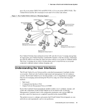
... and seamless layer 2 and layer 3 roaming for all associated WLAN traffic and devices. The DWS-3024L Unified Switch can manage up to 24 D-Link Access Points, whereas the DWS-3024 and the DWS-3026 switches can be directly connected to four peer D-Link Unified Switches that enables WLAN deployment while providing state-of 8000 wireless clients. The...
... and seamless layer 2 and layer 3 roaming for all associated WLAN traffic and devices. The DWS-3024L Unified Switch can manage up to 24 D-Link Access Points, whereas the DWS-3024 and the DWS-3026 switches can be directly connected to four peer D-Link Unified Switches that enables WLAN deployment while providing state-of 8000 wireless clients. The...
User Manual
Page 22
...-8500AP operates in Standalone Mode, you start out with the following D-Link switches: • DWS-3024 (24 GE ports) • DWS-3024L (24 GE ports) • DWS-3026 (24 GE ports + 2 10G ports) D-Link Access Point The D-Link Access Point can operate in the network. The D-Link Unified Access System works with D-Link Access Points in IEEE 802.11a mode.
...-8500AP operates in Standalone Mode, you start out with the following D-Link switches: • DWS-3024 (24 GE ports) • DWS-3024L (24 GE ports) • DWS-3026 (24 GE ports + 2 10G ports) D-Link Access Point The D-Link Access Point can operate in the network. The D-Link Unified Access System works with D-Link Access Points in IEEE 802.11a mode.
User Manual
Page 25
... management of the D-Link Unified Access System up to be on your network size and requirements, and on the same subnet. The Unified Switch and the APs it manages do not need to 48 access points (DWS-3024 and DWS-3026) or 24 access points (DWS-3024L). The Layer 3 ...roaming service allows wireless phone users to roam between access points connected to configure and monitor the D-Link Unified Switch depends on your preference. Understanding the User ...
... management of the D-Link Unified Access System up to be on your network size and requirements, and on the same subnet. The Unified Switch and the APs it manages do not need to 48 access points (DWS-3024 and DWS-3026) or 24 access points (DWS-3024L). The Layer 3 ...roaming service allows wireless phone users to roam between access points connected to configure and monitor the D-Link Unified Switch depends on your preference. Understanding the User ...
User Manual
Page 31
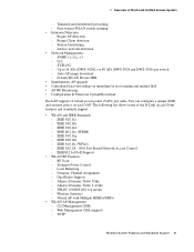
Peer-to 24 APs (DWS-3024L) or 48 APs (DWS-3024 and DWS-3026) per radio. Rogue Client detection - D-Link WLAN Private MIB • Simultaneous AP upgrade • Centralized data forwarding via tunneling for fast roaming and unified QoS • AP RF ...RF Scan - Dual Radio Support - SNMP v1, v2c, v3 - Auto AP image download - IEEE 802.11d - IEEE 802.11g - 1 Overview of the D-Link Access Point features and standards support: • WLAN and IEEE Standards - CLI - Wireless Statistics - Dynamic Channel Assignment - TFTP Wireless System Features and Standards Support 31...
Peer-to 24 APs (DWS-3024L) or 48 APs (DWS-3024 and DWS-3026) per radio. Rogue Client detection - D-Link WLAN Private MIB • Simultaneous AP upgrade • Centralized data forwarding via tunneling for fast roaming and unified QoS • AP RF ...RF Scan - Dual Radio Support - SNMP v1, v2c, v3 - Auto AP image download - IEEE 802.11d - IEEE 802.11g - 1 Overview of the D-Link Access Point features and standards support: • WLAN and IEEE Standards - CLI - Wireless Statistics - Dynamic Channel Assignment - TFTP Wireless System Features and Standards Support 31...
User Manual
Page 39
...Rack - Installation Guidelines - Installing the Optional Modules - Hardware Overview 39 3 Installing the Hardware This chapter provides instructions for installing the D-Link DWS-3024, DWS-3024L, and DWS-3026 switch hardware. Connecting the Switch to the Core Network Hardware Overview This section describes the font, back, and side panels and ...- Side Panels • Installation - Installing the Switch in a Rack - Connecting the Switch and AP through the L2/L3 Network - The DWS-3024/DWS-3024L and DWS-3026 have slightly different front and back panels based on the switch.
...Rack - Installation Guidelines - Installing the Optional Modules - Hardware Overview 39 3 Installing the Hardware This chapter provides instructions for installing the D-Link DWS-3024, DWS-3024L, and DWS-3026 switch hardware. Connecting the Switch to the Core Network Hardware Overview This section describes the font, back, and side panels and ...- Side Panels • Installation - Installing the Switch in a Rack - Connecting the Switch and AP through the L2/L3 Network - The DWS-3024/DWS-3024L and DWS-3026 have slightly different front and back panels based on the switch.
User Manual
Page 40
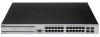
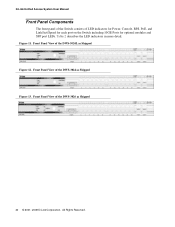
D-Link Unified Access System User Manual Front Panel Components The front panel of the Switch consists of the DWS-3024L as Shipped Figure 12. Front Panel View of the DWS-3026 as Shipped Figure 13. Figure 11. Front Panel View of the DWS-3024 as Shipped 40 © 2001- 2008 D-Link Corporation. Front Panel View of LED indicators for Power, Console, RPS, PoE, and Link/Act/Speed for each port on the Switch including 10GE Ports for optional modules and SFP port LEDs. All Rights Reserved. Table 2 describes the LED indicators in more detail.
D-Link Unified Access System User Manual Front Panel Components The front panel of the Switch consists of the DWS-3024L as Shipped Figure 12. Front Panel View of the DWS-3026 as Shipped Figure 13. Figure 11. Front Panel View of the DWS-3024 as Shipped 40 © 2001- 2008 D-Link Corporation. Front Panel View of LED indicators for Power, Console, RPS, PoE, and Link/Act/Speed for each port on the Switch including 10GE Ports for optional modules and SFP port LEDs. All Rights Reserved. Table 2 describes the LED indicators in more detail.
User Manual
Page 43
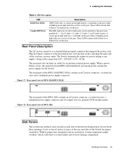
...100 ~ 240 VAC at the rear and sides of the Switch for proper ventilation. Rear Panel Description The AC power connector is no link/activity on the port. The rear panel also includes an outlet for the Switch. When a power failure occurs, the optional external RPS...vent, a redundant power supply connector and two empty slots for Combo 1, Combo 2, Combo 3, and Combo 4 ports. Rear panel view of DWS-3024/DWS-3024L The rear panel of the DWS-3024/DWS-3024L contains an AC power connector, a system fan vent, and a redundant power supply connector. Leave at least 6 inches of the cord into ...
...100 ~ 240 VAC at the rear and sides of the Switch for proper ventilation. Rear Panel Description The AC power connector is no link/activity on the port. The rear panel also includes an outlet for the Switch. When a power failure occurs, the optional external RPS...vent, a redundant power supply connector and two empty slots for Combo 1, Combo 2, Combo 3, and Combo 4 ports. Rear panel view of DWS-3024/DWS-3024L The rear panel of the DWS-3024/DWS-3024L contains an AC power connector, a system fan vent, and a redundant power supply connector. Leave at least 6 inches of the cord into ...


