Product Manual
Page 2
... ...3 Power Failure ...3 Getting Started ...4 Management Options...4 Using Web-based Management Utility...4 Supported Web Browsers ...4 Connecting to the Switch...4 Login Web-based Management Utility ...5 Smart Wizard ...5 Web-based Management Utility...5 SmartConsole Utility...5 Product Introduction ...7 DGS-1216T ...7 Front Panel ...7 Rear Panel...8 DGS-1224T ...8 Front Panel ...8 Rear Panel...9 DGS-1224TP...9 Front Panel ...9 Rear Panel...10 DGS-1248T ...10 Front Panel ...10 Rear Panel...11...
... ...3 Power Failure ...3 Getting Started ...4 Management Options...4 Using Web-based Management Utility...4 Supported Web Browsers ...4 Connecting to the Switch...4 Login Web-based Management Utility ...5 Smart Wizard ...5 Web-based Management Utility...5 SmartConsole Utility...5 Product Introduction ...7 DGS-1216T ...7 Front Panel ...7 Rear Panel...8 DGS-1224T ...8 Front Panel ...8 Rear Panel...9 DGS-1224TP...9 Front Panel ...9 Rear Panel...10 DGS-1248T ...10 Front Panel ...10 Rear Panel...11...

Product Manual
Page 3
...Emission (EMI) Certifications ...3 Safety Certifications...3 Features ...3 L2 Features ...3 VLAN ...3 ii Table of Contents D-Link Web Smart Switch User Manual SNMP Settings ...20 System Settings...21 Identifying the Web-based Management Utility 22 Tool Menu ...22 Reset ...22 Configure Backup & Restore ...23 Firmware Backup and ...33 Configuration > Port Mirroring ...34 Configuration > Power Saving...35 Power over Ethernet (PoE) > PoE Port Settings (Only for DGS-1224TP 36 QoS > 802.1p/DSCP Priority Settings ...37 Security > Trusted Host ...38 Security > Safeguard Engine...39 Security > ...
...Emission (EMI) Certifications ...3 Safety Certifications...3 Features ...3 L2 Features ...3 VLAN ...3 ii Table of Contents D-Link Web Smart Switch User Manual SNMP Settings ...20 System Settings...21 Identifying the Web-based Management Utility 22 Tool Menu ...22 Reset ...22 Configure Backup & Restore ...23 Firmware Backup and ...33 Configuration > Port Mirroring ...34 Configuration > Power Saving...35 Power over Ethernet (PoE) > PoE Port Settings (Only for DGS-1224TP 36 QoS > 802.1p/DSCP Priority Settings ...37 Security > Trusted Host ...38 Security > Safeguard Engine...39 Security > ...

Product Manual
Page 4
Table of Contents D-Link Web Smart Switch User Manual QoS (Quality of Service)...3 Security...3 Management...3 iii
Table of Contents D-Link Web Smart Switch User Manual QoS (Quality of Service)...3 Security...3 Management...3 iii
Product Manual
Page 5
...subjected to append http:// in this guide, the term "Switch" (first letter is strictly forbidden. Trademarks used in the web address. For the latest information about the Web Smart Switches visit: Resource D-Link Technical Support Website www.dlink.com support.dlink.com Terms/... in this document is mainly divided into four parts: 1. About This Guide D-Link Web Smart Switch User Manual About This Guide This guide provides instructions to install D-Link Gigabit Ethernet Web Smart Switches DGS1216T/24T/24TP/48T, how to use the SmartConsole Utility, and to supplementary ...
...subjected to append http:// in this guide, the term "Switch" (first letter is strictly forbidden. Trademarks used in the web address. For the latest information about the Web Smart Switches visit: Resource D-Link Technical Support Website www.dlink.com support.dlink.com Terms/... in this document is mainly divided into four parts: 1. About This Guide D-Link Web Smart Switch User Manual About This Guide This guide provides instructions to install D-Link Gigabit Ethernet Web Smart Switches DGS1216T/24T/24TP/48T, how to use the SmartConsole Utility, and to supplementary ...

Product Manual
Page 6
...missing or damaged, please contact the local reseller for palm size switches). Figure 1 - To install, attach the mounting brackets to the AC power connector. One D-Link Web-Smart Switch One AC power cord Four rubber feet Screws and two mounting ...proper heat dissipation and adequate ventilation around it is missing or damaged, please contact your local D-Link reseller for the D-Link Web-Smart Switch. 1 Hardware Installation D-Link Web Smart Switch User Manual 1 Hardware Installation This chapter provides unpacking and installation information for replacement. Please consult ...
...missing or damaged, please contact the local reseller for palm size switches). Figure 1 - To install, attach the mounting brackets to the AC power connector. One D-Link Web-Smart Switch One AC power cord Four rubber feet Screws and two mounting ...proper heat dissipation and adequate ventilation around it is missing or damaged, please contact your local D-Link reseller for the D-Link Web-Smart Switch. 1 Hardware Installation D-Link Web Smart Switch User Manual 1 Hardware Installation This chapter provides unpacking and installation information for replacement. Please consult ...

Product Manual
Page 7
Plugging in the AC Power Cord Users may now connect the AC power cord into an outlet Power Failure As a precaution, the switch should be unplugged in the rack. Figure 4 -Plugging the switch into the rear of power failure. When power is grounded and surge protected). Mount the Switch in . 3 Figure 3 - 1 Hardware Installation D-Link Web Smart Switch User Manual Then, use the screws provided with the equipment rack to mount the switch in case of the switch and to an electrical outlet (preferably one that is resumed, plug the switch back in the rack or chassis Step 3 -
Plugging in the AC Power Cord Users may now connect the AC power cord into an outlet Power Failure As a precaution, the switch should be unplugged in the rack. Figure 4 -Plugging the switch into the rear of power failure. When power is grounded and surge protected). Mount the Switch in . 3 Figure 3 - 1 Hardware Installation D-Link Web Smart Switch User Manual Then, use the screws provided with the equipment rack to mount the switch in case of the switch and to an electrical outlet (preferably one that is resumed, plug the switch back in the rack or chassis Step 3 -

Product Manual
Page 8
... installation instructions for communication with a RJ-45 Ethernet connection 2. Using the SmartConsole Utility, you want to manage multiple D-Link Web Smart Switches, the SmartConsole Utility is easy to start the initial setting of D-Link Web-Smart Switch. 2 Getting Started D-Link Web Smart Switch User Manual 2 Getting Started This chapter guides you how to get into and introduces the management interface of multiple...
... installation instructions for communication with a RJ-45 Ethernet connection 2. Using the SmartConsole Utility, you want to manage multiple D-Link Web Smart Switches, the SmartConsole Utility is easy to start the initial setting of D-Link Web-Smart Switch. 2 Getting Started D-Link Web Smart Switch User Manual 2 Getting Started This chapter guides you how to get into and introduces the management interface of multiple...

Product Manual
Page 9
...168.0.1 with the same L2 network segment connected to your web browser and enter 192.168.0.1 (the factory-default IP address) in the same subnet as it appears in Smart Wizard, you to quick configure the D-Link Web Smart Switch. Figure 7 - This tool is only for computers running... in the Monitor List. Please refer to Chapter 5 Configuration for detail configurations. 2 Getting Started D-Link Web Smart Switch User Manual Login Web-based Management Utility In order to login and configure the switch via an Ethernet connection, the PC must have an IP address of 192.168.0.x (where x...
...168.0.1 with the same L2 network segment connected to your web browser and enter 192.168.0.1 (the factory-default IP address) in the same subnet as it appears in Smart Wizard, you to quick configure the D-Link Web Smart Switch. Figure 7 - This tool is only for computers running... in the Monitor List. Please refer to Chapter 5 Configuration for detail configurations. 2 Getting Started D-Link Web Smart Switch User Manual Login Web-based Management Utility In order to login and configure the switch via an Ethernet connection, the PC must have an IP address of 192.168.0.x (where x...
Product Manual
Page 10
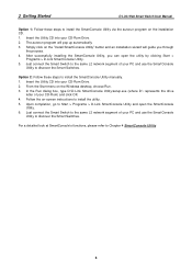
2 Getting Started D-Link Web Smart Switch User Manual Option 1: Follow these steps to install the SmartConsole Utility via the autorun program on the installation CD. 1. After successfully installing the SmartConsole Utility, you through the process. 4. In the Run dialog box, type D:\D-Link SmartConsole Utility\setup.exe (where D:\ represents the drive letter of your PC and use...
2 Getting Started D-Link Web Smart Switch User Manual Option 1: Follow these steps to install the SmartConsole Utility via the autorun program on the installation CD. 1. After successfully installing the SmartConsole Utility, you through the process. 4. In the Run dialog box, type D:\D-Link SmartConsole Utility\setup.exe (where D:\ represents the drive letter of your PC and use...
Product Manual
Page 11
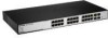
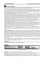
...provides easy initial setting of shared resources such as password change, firmware upgrade. 3 Product Introduction D-Link Web Smart Switch User Manual 3 Product Introduction Thank you and congratulations on the screen for instant access. Since ...smart switches. DGS-1216T Front Panel Power LED: The Power LED flashes when the Switch is in MIB browser to enhance network security and performance. Extensive Layer 2 Features: Implemented as complete L2 devices, these switches for fast, reliable data transfer. Versatile Management: The new generation of Gigabit web smart switches...
...provides easy initial setting of shared resources such as password change, firmware upgrade. 3 Product Introduction D-Link Web Smart Switch User Manual 3 Product Introduction Thank you and congratulations on the screen for instant access. Since ...smart switches. DGS-1216T Front Panel Power LED: The Power LED flashes when the Switch is in MIB browser to enhance network security and performance. Extensive Layer 2 Features: Implemented as complete L2 devices, these switches for fast, reliable data transfer. Versatile Management: The new generation of Gigabit web smart switches...
Product Manual
Page 12
...green light denotes a valid 1000Mbps link on the corresponding port, a steady orange light denotes a valid 10 or 100Mbps link on 1000Mbps. Power: The power port is used, the RJ-45 port cannot be lost. 3 Product Introduction D-Link Web Smart Switch User Manual NOTE: On DGS-1216T, the MiniGBIC ports 15F... and 16F are shared with 2 Combo SFP Smart Switch Front Panel Figure 10 - When MiniGBIC port is where to the default configuration ...
...green light denotes a valid 1000Mbps link on the corresponding port, a steady orange light denotes a valid 10 or 100Mbps link on 1000Mbps. Power: The power port is used, the RJ-45 port cannot be lost. 3 Product Introduction D-Link Web Smart Switch User Manual NOTE: On DGS-1216T, the MiniGBIC ports 15F... and 16F are shared with 2 Combo SFP Smart Switch Front Panel Figure 10 - When MiniGBIC port is where to the default configuration ...

Product Manual
Page 13
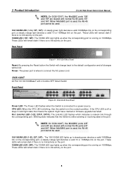
... might have crashed or firmware upgrade has failed. CPU LED: When the CPU LED is blinking, then the switch is off indicates all changes will solid green to a power source. DGS-1224TP 24 Port 10/100/1000BaseT PoE with 4 Combo SFP Smart Switch Front Panel Figure 12 - 3 Product Introduction Rear Panel D-Link Web Smart Switch User Manual Figure 11 -
... might have crashed or firmware upgrade has failed. CPU LED: When the CPU LED is blinking, then the switch is off indicates all changes will solid green to a power source. DGS-1224TP 24 Port 10/100/1000BaseT PoE with 4 Combo SFP Smart Switch Front Panel Figure 12 - 3 Product Introduction Rear Panel D-Link Web Smart Switch User Manual Figure 11 -
Product Manual
Page 14
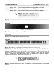
...1000Mbps). CPU LED: When the CPU LED is blinking, then the switch is where to 24F are shared with 4 Combo SFP Smart Switch Front Panel Figure 14 - When MiniGBIC port is used . 3 Product Introduction D-Link Web Smart Switch User Manual Blinking Green Solid Orange Blinking Orange Data is sending or... light denotes a valid 10 or 100Mbps link on the port while a blinking orange light indicates activity on corresponding port at 100Mbps NOTE: On DGS-1224TP, the MiniGBIC ports 21F to connect the AC power cord. Rear Panel Figure 13 - DGS-1224TP Rear Panel Power: The power port is...
...1000Mbps). CPU LED: When the CPU LED is blinking, then the switch is where to 24F are shared with 4 Combo SFP Smart Switch Front Panel Figure 14 - When MiniGBIC port is used . 3 Product Introduction D-Link Web Smart Switch User Manual Blinking Green Solid Orange Blinking Orange Data is sending or... light denotes a valid 10 or 100Mbps link on the port while a blinking orange light indicates activity on corresponding port at 100Mbps NOTE: On DGS-1224TP, the MiniGBIC ports 21F to connect the AC power cord. Rear Panel Figure 13 - DGS-1224TP Rear Panel Power: The power port is...
Product Manual
Page 15
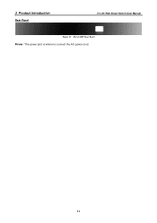
DGS-1248T Rear Panel Power: The power port is where to connect the AC power cord. 11 3 Product Introduction Rear Panel D-Link Web Smart Switch User Manual Figure 15 -
DGS-1248T Rear Panel Power: The power port is where to connect the AC power cord. 11 3 Product Introduction Rear Panel D-Link Web Smart Switch User Manual Figure 15 -
Product Manual
Page 16
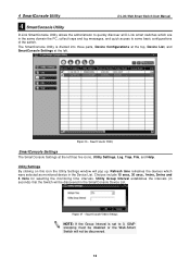
...domain the PC, collect traps and log messages, and quick access to 0, IGMP snooping must be disabled or the Web-Smart Switch will not be discovered in the SmartConsole Device List. Utility Settings By clicking on this icon the Utility Settings window ... that the Switch will be discovered. 12 Choices include 15 secs, 30 secs, 1mins, 2mins and 5 mins for selecting the monitoring time intervals. 4 SmartConsole Utility D-Link Web Smart Switch User Manual 4 SmartConsole Utility D-Link SmartConsole Utility allows the administrator to quickly discover all D-Link smart switches which were ...
...domain the PC, collect traps and log messages, and quick access to 0, IGMP snooping must be disabled or the Web-Smart Switch will not be discovered in the SmartConsole Device List. Utility Settings By clicking on this icon the Utility Settings window ... that the Switch will be discovered. 12 Choices include 15 secs, 30 secs, 1mins, 2mins and 5 mins for selecting the monitoring time intervals. 4 SmartConsole Utility D-Link Web Smart Switch User Manual 4 SmartConsole Utility D-Link SmartConsole Utility allows the administrator to quickly discover all D-Link smart switches which were ...

Product Manual
Page 17
Click OK to exit. Click Clear Log to show the events of the SmartConsole Utility and the device. 4 SmartConsole Utility D-Link Web Smart Switch User Manual Log By clicking on this icon the Trap window will pop up . Date/Time indicates when the trap was received File By clicking ...
Click OK to exit. Click Clear Log to show the events of the SmartConsole Utility and the device. 4 SmartConsole Utility D-Link Web Smart Switch User Manual Log By clicking on this icon the Trap window will pop up . Date/Time indicates when the trap was received File By clicking ...
Product Manual
Page 18
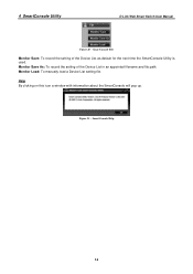
Help By clicking on this icon a window with information about the SmartConsole will pop up. Monitor Save As: To record the setting of the Device List as default for the next time the SmartConsole Utility is used. SmartConsole File Monitor Save: To record the setting of the Device List in an appointed filename and file path. Figure 21 - SmartConsole Help 14 4 SmartConsole Utility D-Link Web Smart Switch User Manual Figure 20 - Monitor Load: To manually load a Device List setting file.
Help By clicking on this icon a window with information about the SmartConsole will pop up. Monitor Save As: To record the setting of the Device List as default for the next time the SmartConsole Utility is used. SmartConsole File Monitor Save: To record the setting of the Device List in an appointed filename and file path. Figure 21 - SmartConsole Help 14 4 SmartConsole Utility D-Link Web Smart Switch User Manual Figure 20 - Monitor Load: To manually load a Device List setting file.

Product Manual
Page 19
... will pop up. Here you can configure the Product Name, IP Address, Gateway, Subnet Mask, System Name, Location, Trap IP, Switch Group Interval, and DHCP Setting of the Switch. 4 SmartConsole Utility D-Link Web Smart Switch User Manual Device Configurations The Device Configurations in Confirm Password then click OK Figure 22 - To apply the configuration, insert the...
... will pop up. Here you can configure the Product Name, IP Address, Gateway, Subnet Mask, System Name, Location, Trap IP, Switch Group Interval, and DHCP Setting of the Switch. 4 SmartConsole Utility D-Link Web Smart Switch User Manual Device Configurations The Device Configurations in Confirm Password then click OK Figure 22 - To apply the configuration, insert the...
Product Manual
Page 20
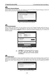
.... Entering the correct Device Password then press OK, the device will popup. Switch may crash if firmware upgrade incompletely. Figure 25 - SmartConsole Device Password Manager Firmware Upgrade Select a switch from the Device List, then clicking on this icon the Device Password Manager ... a Firmware Path (or you 're going to complete the firmware upgrade Figure 24 - 4 SmartConsole Utility D-Link Web Smart Switch User Manual Device Password Manager Select a switch from the Device List, then clicking on this icon the Firmware Upgrade window will pop up to use then input...
.... Entering the correct Device Password then press OK, the device will popup. Switch may crash if firmware upgrade incompletely. Figure 25 - SmartConsole Device Password Manager Firmware Upgrade Select a switch from the Device List, then clicking on this icon the Device Password Manager ... a Firmware Path (or you 're going to complete the firmware upgrade Figure 24 - 4 SmartConsole Utility D-Link Web Smart Switch User Manual Device Password Manager Select a switch from the Device List, then clicking on this icon the Firmware Upgrade window will pop up to use then input...

Product Manual
Page 21
Add(+), Delete(-) and Discover the device By pressing the Discovery button, all the Web-Smart devices locate in the same domain with the management PC are listed in the device list. SmartConsole Add device Figure 27 - You may ...Device List. Click the + and insert the device IP address to remove it. Figure 26 - Here you can configure the Switch through the Web-based Management Utility. 4 SmartConsole Utility D-Link Web Smart Switch User Manual Web Access Select a switch from the Device List, then clicking this icon an internet browser will pop up (default is Internet Explorer).
Add(+), Delete(-) and Discover the device By pressing the Discovery button, all the Web-Smart devices locate in the same domain with the management PC are listed in the device list. SmartConsole Add device Figure 27 - You may ...Device List. Click the + and insert the device IP address to remove it. Figure 26 - Here you can configure the Switch through the Web-based Management Utility. 4 SmartConsole Utility D-Link Web Smart Switch User Manual Web Access Select a switch from the Device List, then clicking this icon an internet browser will pop up (default is Internet Explorer).