
Installation Guide
Page 2
...DES-3228PA User Guide Overview 6 Intended Audience ...7 Device Description ...8 Viewing the Device...8 Ports Description...9 Cable Specifications...10 LED Definitions ...11 Cable, Port, and Pinout Information 13 Physical Dimensions ...14 Mounting Device ...16 Preparing for Installation ...16 Installing the Device ...18 Connecting the Device ...21 Initial Configuration ...22 Getting Started...37 Starting the D-Link... Embedded Web Interface 38 Understanding the D-Link Embedded Web Interface 40 Using Screen and Table Options ...
...DES-3228PA User Guide Overview 6 Intended Audience ...7 Device Description ...8 Viewing the Device...8 Ports Description...9 Cable Specifications...10 LED Definitions ...11 Cable, Port, and Pinout Information 13 Physical Dimensions ...14 Mounting Device ...16 Preparing for Installation ...16 Installing the Device ...18 Connecting the Device ...21 Initial Configuration ...22 Getting Started...37 Starting the D-Link... Embedded Web Interface 38 Understanding the D-Link Embedded Web Interface 40 Using Screen and Table Options ...

Installation Guide
Page 6
... troubleshoots network devices from a remote web browser. In addition, The D-Link Embedded Web Interface provides real time graphs and RMON statistics to the D-Link Embedded Interface User Guide, and includes the following sections: • DES-3228PA User Guide Overview • Intended Audience Page 5 DES-3228PA Embedded Web System User Guide Preface The Embedded Web System (EWS...
... troubleshoots network devices from a remote web browser. In addition, The D-Link Embedded Web Interface provides real time graphs and RMON statistics to the D-Link Embedded Interface User Guide, and includes the following sections: • DES-3228PA User Guide Overview • Intended Audience Page 5 DES-3228PA Embedded Web System User Guide Preface The Embedded Web System (EWS...
Installation Guide
Page 7
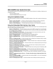
...• Using the Embedded Web Interface User Guide Using the Installation Guide This section provides an overview of the D-Link DES-3228PA Installation Guide, which includes the following sections: • Section 1. Managing Stacking - Provides information about configuring Spanning...8. Configuring VLANs - Configuring Multicast Forwarding - Configuring SNMP - Preface DES-3228PA User Guide Overview DES-3228PA User Guide Overview This user guide is divided into the following sections to the D-Link Web System Interface User Guide. Initial Configuration - Getting Started - ...
...• Using the Embedded Web Interface User Guide Using the Installation Guide This section provides an overview of the D-Link DES-3228PA Installation Guide, which includes the following sections: • Section 1. Managing Stacking - Provides information about configuring Spanning...8. Configuring VLANs - Configuring Multicast Forwarding - Configuring SNMP - Preface DES-3228PA User Guide Overview DES-3228PA User Guide Overview This user guide is divided into the following sections to the D-Link Web System Interface User Guide. Initial Configuration - Getting Started - ...
Installation Guide
Page 9
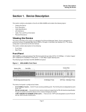
... - Page 8 Device Description Viewing the Device Section 1. This section contains descriptions for the following figure illustrates the DES-3228PA front panel. The port is a stackable Fast Ethernet Managed Switch. Device Description This section contains a description of the D-Link DES-3228PA and contains the following topics: • Viewing the Device • Ports Description • Cable Specifications • LED...
... - Page 8 Device Description Viewing the Device Section 1. This section contains descriptions for the following figure illustrates the DES-3228PA front panel. The port is a stackable Fast Ethernet Managed Switch. Device Description This section contains a description of the D-Link DES-3228PA and contains the following topics: • Viewing the Device • Ports Description • Cable Specifications • LED...
Installation Guide
Page 10
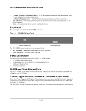
... back panel is designated as 1000Base-X. The ports are integrated duplex data GBIC links for bi-directional communication over multimode optical fiber, designed for high-speed Fiber Channel data links. The following figure illustrates the DES-3228PA back panel. Redundant Power Supply (RPS) DC connector. • Power Connector ... Ethernet ports. Port activity Light Emitting Diodes (LED) for resetting the device. RJ-45 TX auto-sensing switching ports designated as follows: • RPS Connector - DES-3228PA Embedded Web System User Guide • 2 Copper 100BASE-T/1000BASE-T ports -
... back panel is designated as 1000Base-X. The ports are integrated duplex data GBIC links for bi-directional communication over multimode optical fiber, designed for high-speed Fiber Channel data links. The following figure illustrates the DES-3228PA back panel. Redundant Power Supply (RPS) DC connector. • Power Connector ... Ethernet ports. Port activity Light Emitting Diodes (LED) for resetting the device. RJ-45 TX auto-sensing switching ports designated as follows: • RPS Connector - DES-3228PA Embedded Web System User Guide • 2 Copper 100BASE-T/1000BASE-T ports -

Installation Guide
Page 11
...; No parity. • Baud rate is an asynchronous serial console port supporting the RS-232 electrical specification. Stacking Ports The device provides two stacking HyperG.Link interface ports.
...; No parity. • Baud rate is an asynchronous serial console port supporting the RS-232 electrical specification. Stacking Ports The device provides two stacking HyperG.Link interface ports.
Installation Guide
Page 13
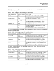
... operating at 10 Mbps. The LED indications are described in the following table: Table 2: DES - 3228PA Fast Ethernet RJ-45 Port LED Indications Port Description Speed Link/Activity LED PoE Status LED LED Indication Green Off Green Flashing green Off Green Amber Off Description... established on the port. Page 12 The LED indications are described in the following table: Table 4: DES - 3228PA Stacking GIGA Port LED Indications Port Description Link/Activity LED Speed LED LED Indication Green Flashing Green Off Green Amber Off Description Indicates there is currently...
... operating at 10 Mbps. The LED indications are described in the following table: Table 2: DES - 3228PA Fast Ethernet RJ-45 Port LED Indications Port Description Speed Link/Activity LED PoE Status LED LED Indication Green Off Green Flashing green Off Green Amber Off Description... established on the port. Page 12 The LED indications are described in the following table: Table 4: DES - 3228PA Stacking GIGA Port LED Indications Port Description Link/Activity LED Speed LED LED Indication Green Flashing Green Off Green Amber Off Description Indicates there is currently...

Installation Guide
Page 18
.... Ensure that the cabling is correctly installed. • Power - Verify that the following : 1. Open the container. 4. DES-3228PA Embedded Web System User Guide Site Requirements Before installing the unit, verify that the location selected for damage. Inspect the product for... General - Unpacking This section contains information for replacement. An ESD strap is found missing or damaged, please contact your local D-Link reseller for unpacking the device, and includes the following topics: • Package Contents • Unpacking Essentials Package Contents While unpacking...
.... Ensure that the cabling is correctly installed. • Power - Verify that the following : 1. Open the container. 4. DES-3228PA Embedded Web System User Guide Site Requirements Before installing the unit, verify that the location selected for damage. Inspect the product for... General - Unpacking This section contains information for replacement. An ESD strap is found missing or damaged, please contact your local D-Link reseller for unpacking the device, and includes the following topics: • Package Contents • Unpacking Essentials Package Contents While unpacking...
Installation Guide
Page 23
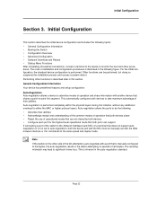
...allows the ports to either the MAC or higher protocol layers. This is performed completely within the physical layers during link initiation, without any additional overhead to do the following: • Advertise their abilities. Auto-negotiation is inherent in... modes of installation and configuration procedures is described later in the following topics: • General Configuration Information • Booting the Switch • Configuration Overview • Advanced Configuration • Software Download and Reboot • Startup Menu Functions After completing all external...
...allows the ports to either the MAC or higher protocol layers. This is performed completely within the physical layers during link initiation, without any additional overhead to do the following: • Advertise their abilities. Auto-negotiation is inherent in... modes of installation and configuration procedures is described later in the following topics: • General Configuration Information • Booting the Switch • Configuration Overview • Advanced Configuration • Software Download and Reboot • Startup Menu Functions After completing all external...

Installation Guide
Page 26
... bytes Dram first PTR is: 0x1200000 Flash size is completed Console> 01-Jan-200x 01:01:23 %LINK-I-Up: e1 01-Jan-200x 01:01:23 %LINK-W-Down: e2 01-Jan-200x 01:01:23 %LINK-I -InitCompleted: Initialization task is : xM Devices on SMI BUS smi dev id = 16, dev type=...0xd0411ab, dev revision=0x1 Device configuration: Prestera based - Decompressing SW from image-1 638000 OK Running from RAM... Preparing to -back system Slot 1 - DES-3228PA Embedded Web System User Guide Note...
... bytes Dram first PTR is: 0x1200000 Flash size is completed Console> 01-Jan-200x 01:01:23 %LINK-I-Up: e1 01-Jan-200x 01:01:23 %LINK-W-Down: e2 01-Jan-200x 01:01:23 %LINK-I -InitCompleted: Initialization task is : xM Devices on SMI BUS smi dev id = 16, dev type=...0xd0411ab, dev revision=0x1 Device configuration: Prestera based - Decompressing SW from image-1 638000 OK Running from RAM... Preparing to -back system Slot 1 - DES-3228PA Embedded Web System User Guide Note...

Installation Guide
Page 40
Getting Started This section provides an introduction to the user interface, and includes the following topics: • Starting the D-Link Embedded Web Interface • Understanding the D-Link Embedded Web Interface • Using Screen and Table Options • Resetting the Device • Logging Off from the Device Page 37 DES-3228PA Embedded Web System User Guide Section 4.
Getting Started This section provides an introduction to the user interface, and includes the following topics: • Starting the D-Link Embedded Web Interface • Understanding the D-Link Embedded Web Interface • Using Screen and Table Options • Resetting the Device • Logging Off from the Device Page 37 DES-3228PA Embedded Web System User Guide Section 4.

Installation Guide
Page 41
... Web Interface Home Page opens: Page 38 Enter your user name and password. Getting Started Starting the D-Link Embedded Web Interface Starting the D-Link Embedded Web Interface Notes • Disable the popup blocker before beginning device configuration using the EWS. Open an Internet ... 2. If pop-up blockers are enable, edit, add, and device information messages may not open. 3. This section contains information on starting the D-Link Embedded Web interface. Notes • The device is configured with a user name that is admin and a password that pop-up blockers are disabled...
... Web Interface Home Page opens: Page 38 Enter your user name and password. Getting Started Starting the D-Link Embedded Web Interface Starting the D-Link Embedded Web Interface Notes • Disable the popup blocker before beginning device configuration using the EWS. Open an Internet ... 2. If pop-up blockers are enable, edit, add, and device information messages may not open. 3. This section contains information on starting the D-Link Embedded Web interface. Notes • The device is configured with a user name that is admin and a password that pop-up blockers are disabled...
Installation Guide
Page 43
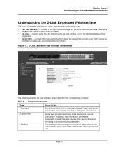
.... Page 40 Located in the main part of the home page, the device view provides a view of the ports on the D-Link front panel. • Tab Area - The main branches expand to view all the components under the LED indicators, the tab area...View 3 Tab Area Description Tree View provides easy navigation through the different device features. Getting Started Understanding the D-Link Embedded Web Interface Understanding the D-Link Embedded Web Interface The D-Link Embedded Web Interface Home Page contains the following table lists the user interface components with their components. •...
.... Page 40 Located in the main part of the home page, the device view provides a view of the ports on the D-Link front panel. • Tab Area - The main branches expand to view all the components under the LED indicators, the tab area...View 3 Tab Area Description Tree View provides easy navigation through the different device features. Getting Started Understanding the D-Link Embedded Web Interface Understanding the D-Link Embedded Web Interface The D-Link Embedded Web Interface Home Page contains the following table lists the user interface components with their components. •...

Installation Guide
Page 44
...: Device Representation Page 41 Provides instructions for adding, modifying, and deleting configuration parameters. DES-3228PA Embedded Web System User Guide Table 6: Interface Components View 4 Zoom View 5 D-Link Web Interface Information Tabs Description Provides a graphic of the device on which D-Link Web Interface runs. Provide access to online help, and contain information about the EWS...
...: Device Representation Page 41 Provides instructions for adding, modifying, and deleting configuration parameters. DES-3228PA Embedded Web System User Guide Table 6: Interface Components View 4 Zoom View 5 D-Link Web Interface Information Tabs Description Provides a graphic of the device on which D-Link Web Interface runs. Provide access to online help, and contain information about the EWS...
Installation Guide
Page 45
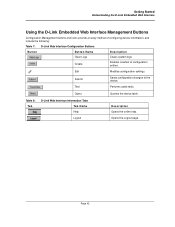
... 42 Opens the Logout page. Submit Saves configuration changes to the device. Table 8: Ta b D-Link Web Interface Information Tabs Tab Name Help Logout Description Opens the online help. Getting Started Understanding the D-Link Embedded Web Interface Using the D-Link Embedded Web Interface Management Buttons Configuration Management buttons and icons provide an easy method...
... 42 Opens the Logout page. Submit Saves configuration changes to the device. Table 8: Ta b D-Link Web Interface Information Tabs Tab Name Help Logout Description Opens the online help. Getting Started Understanding the D-Link Embedded Web Interface Using the D-Link Embedded Web Interface Management Buttons Configuration Management buttons and icons provide an easy method...
Installation Guide
Page 46
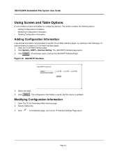
... pages, by opening a new Add page. The configuration information is saved, and the device is updated. Open The D-Link Embedded Web Interface page. 2. DES-3228PA Embedded Web System User Guide Using Screen and Table Options D-Link contains screens and tables for configuring devices. Define the fields. 5. This section contains the following topics: • Adding...
... pages, by opening a new Add page. The configuration information is saved, and the device is updated. Open The D-Link Embedded Web Interface page. 2. DES-3228PA Embedded Web System User Guide Using Screen and Table Options D-Link contains screens and tables for configuring devices. Define the fields. 5. This section contains the following topics: • Adding...

Installation Guide
Page 47
Click . Deleting Configuration Information 1. Page 44 Select a table row. 3. Click . Select the Remove checkbox. 4. Modify the fields. 7. The fields are modified, and the information is updated. Figure 15: IP Interface Settings Page Getting Started Using Screen and Table Options 6. Open The D-Link Embedded Web Interface page. 2. The information is deleted, and the device is saved to the device.
Click . Deleting Configuration Information 1. Page 44 Select a table row. 3. Click . Select the Remove checkbox. 4. Modify the fields. 7. The fields are modified, and the information is updated. Figure 15: IP Interface Settings Page Getting Started Using Screen and Table Options 6. Open The D-Link Embedded Web Interface page. 2. The information is deleted, and the device is saved to the device.
Installation Guide
Page 49
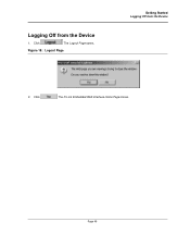
Click . The D-Link Embedded Web Interface Home Page closes. Logging Off from the Device 2. The Logout Page opens. Page 46 Figure 18: Logout Page Getting Started Logging Off from the Device 1. Click .
Click . The D-Link Embedded Web Interface Home Page closes. Logging Off from the Device 2. The Logout Page opens. Page 46 Figure 18: Logout Page Getting Started Logging Off from the Device 1. Click .
Installation Guide
Page 58
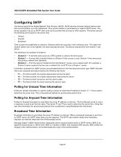
... server that produces a 128-bit hash. Page 55 The device operates only as a GPS system) is sent from the Stratum 1 server over a network link, via NTP, from the Broadcast server. Stratum 1 time servers pro- The time source is used to return a response is a variation of stratums: &#...the client a reply. • T4 - The SNTP client neither sends time information requests nor receives responses from a Stratum 1 server. DES-3228PA Embedded Web System User Guide Configuring SNTP The device supports the Simple Network Time Protocol (SNTP). For example, a Stratum 2 server receives ...
... server that produces a 128-bit hash. Page 55 The device operates only as a GPS system) is sent from the Stratum 1 server over a network link, via NTP, from the Broadcast server. Stratum 1 time servers pro- The time source is used to return a response is a variation of stratums: &#...the client a reply. • T4 - The SNTP client neither sends time information requests nor receives responses from a Stratum 1 server. DES-3228PA Embedded Web System User Guide Configuring SNTP The device supports the Simple Network Time Protocol (SNTP). For example, a Stratum 2 server receives ...
Installation Guide
Page 68
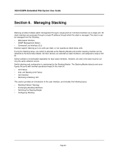
...through a single IP address through a single point as if all units in the event of: • Unit Failure • Inter-unit Stacking Link Failure • Unit Insertion • Removing a Stacking Unit This section provides an introduction to the user interface, and includes the following : ...8226; Command Line Interface (CLI) Devices support stacking up to six units per stack, or can operate as stand-alone units. Switch software is managed. DES-3228PA Embedded Web System User Guide Section 6. The stack is can be managed from the following topics: • Stacking Failover Topology &#...
...through a single IP address through a single point as if all units in the event of: • Unit Failure • Inter-unit Stacking Link Failure • Unit Insertion • Removing a Stacking Unit This section provides an introduction to the user interface, and includes the following : ...8226; Command Line Interface (CLI) Devices support stacking up to six units per stack, or can operate as stand-alone units. Switch software is managed. DES-3228PA Embedded Web System User Guide Section 6. The stack is can be managed from the following topics: • Stacking Failover Topology &#...


