Product Manual
Page 4
TABLE OF CONTENTS About This Guide 6 Purpose 6 Terms/Usage 6 Introduction 7 Fast Ethernet Technology 7 Switching Technology 7 VLAN (Virtual Local Area Network 8 Power over Ethernet (PoE 9 Features 9 Unpacking and Installation 11 Unpacking 11 Installation 11 Rack Mounting 12 Connecting Network Cable 13 AC Power 13 Identifying External Components 14 Front Panel 14 Rear Panel 15 Understanding LED Indicators 16 Power and CPU LEDs 16 Ports 1~8 PoE port status LEDs 16 Ports 9~16 Ethernet port status LEDs 17 4
TABLE OF CONTENTS About This Guide 6 Purpose 6 Terms/Usage 6 Introduction 7 Fast Ethernet Technology 7 Switching Technology 7 VLAN (Virtual Local Area Network 8 Power over Ethernet (PoE 9 Features 9 Unpacking and Installation 11 Unpacking 11 Installation 11 Rack Mounting 12 Connecting Network Cable 13 AC Power 13 Identifying External Components 14 Front Panel 14 Rear Panel 15 Understanding LED Indicators 16 Power and CPU LEDs 16 Ports 1~8 PoE port status LEDs 16 Ports 9~16 Ethernet port status LEDs 17 4

Product Manual
Page 5
Configuration 18 Installing the Web Management Utility 18 Discovery List 20 Monitor List 21 Device Setting 23 Toolbar 25 Configuring the Switch 26 Login 27 Setup Menu 30 Configuring Setup Setting 31 Port Settings 31 VLAN Settings (Virtual Local Area Network 33 Trunk Setting 35 Mirror Setting 36 PoE Setting 37 Device Status 39 Statistic 40 System Setting 42 Trap Setting 43 Set Password 44 Backup Setting 45 Reset Setting 46 Logout 46 Technical Specifications 48 5
Configuration 18 Installing the Web Management Utility 18 Discovery List 20 Monitor List 21 Device Setting 23 Toolbar 25 Configuring the Switch 26 Login 27 Setup Menu 30 Configuring Setup Setting 31 Port Settings 31 VLAN Settings (Virtual Local Area Network 33 Trunk Setting 35 Mirror Setting 36 PoE Setting 37 Device Status 39 Statistic 40 System Setting 42 Trap Setting 43 Set Password 44 Backup Setting 45 Reset Setting 46 Logout 46 Technical Specifications 48 5

Product Manual
Page 6
...power through Port-1 to Port-8. Terms/Usage In this Switch's Port-1 to Port-8 are Power over Ethernet (PoE) ports, it will automatically detect the presence of the 8-Port 10/100Mbps Ethernet Web Smart Switch with 8 10/100Mbps PoE ports and "switch" (first letter lower case) refers to other PD...how to install your Web-Smart 8-Port 10/100Mbps Ethernet Web-Smart Switch with 8-Port PoE. Since this guide, the term "Switch" (first letter upper case) refers to your Web-Smart16-Port 10/100Mbps Ethernet Switch. ABOUT THIS GUIDE Congratulations on your purchase of IEEE 802.3af-compliant...
...power through Port-1 to Port-8. Terms/Usage In this Switch's Port-1 to Port-8 are Power over Ethernet (PoE) ports, it will automatically detect the presence of the 8-Port 10/100Mbps Ethernet Web Smart Switch with 8 10/100Mbps PoE ports and "switch" (first letter lower case) refers to other PD...how to install your Web-Smart 8-Port 10/100Mbps Ethernet Web-Smart Switch with 8-Port PoE. Since this guide, the term "Switch" (first letter upper case) refers to your Web-Smart16-Port 10/100Mbps Ethernet Switch. ABOUT THIS GUIDE Congratulations on your purchase of IEEE 802.3af-compliant...

Product Manual
Page 9
... overall installation costs by the IEEE to facilitate the spanning of VLANs across multiple switches. (Reference: IEEE Std 802.1Q-1998 Virtual Bridged Local Area Networks.) Power over Ethernet (PoE) Power over Ethernet (PoE) integrates power and data onto one single cabling infrastructure, eliminating the need to ... LAN access points, and IP security cameras. Power and Data are integrated onto the same cable. Supporting category 5/5e up -link port Full-/half- PoE is a standard set by eliminating the need to have AC power available at all locations. Features 16×10/100Mbps Auto-...
... overall installation costs by the IEEE to facilitate the spanning of VLANs across multiple switches. (Reference: IEEE Std 802.1Q-1998 Virtual Bridged Local Area Networks.) Power over Ethernet (PoE) Power over Ethernet (PoE) integrates power and data onto one single cabling infrastructure, eliminating the need to ... LAN access points, and IP security cameras. Power and Data are integrated onto the same cable. Supporting category 5/5e up -link port Full-/half- PoE is a standard set by eliminating the need to have AC power available at all locations. Features 16×10/100Mbps Auto-...

Product Manual
Page 11
... a fairly cool and dry place. When installing, consider the following items: One 16-Port 10/100Mbps Ethernet Web Smart Switch with 8-Port PoE One AC power cord, suitable for your area's electrical power connections Four rubber feet to sunlight. 11 UNPACKING AND INSTALLATION This chapter provides unpacking and ...
... a fairly cool and dry place. When installing, consider the following items: One 16-Port 10/100Mbps Ethernet Web Smart Switch with 8-Port PoE One AC power cord, suitable for your area's electrical power connections Four rubber feet to sunlight. 11 UNPACKING AND INSTALLATION This chapter provides unpacking and ...
Product Manual
Page 13
...system fan. These RJ45 ports are PoE Enable ports. The Switch's power supply will not offer the power to the connected PoE device. The power switch is identified. These PoE ports will supply power through the Ethernet port to these devices. The Switch supports 10Mbps Ethernet or 100Mbps Fast ...Ethernet and it runs both in half- The Switch will be turned on their network...
...system fan. These RJ45 ports are PoE Enable ports. The Switch's power supply will not offer the power to the connected PoE device. The power switch is identified. These PoE ports will supply power through the Ethernet port to these devices. The Switch supports 10Mbps Ethernet or 100Mbps Fast ...Ethernet and it runs both in half- The Switch will be turned on their network...

Product Manual
Page 14
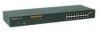
...and play" capability. Figure 3. Front Panel The figure below ). The PoE port will be automatically activated when a compatible terminal is a NIC (Network Interface Card) or switch and hub. 14 For Legacy devices that are PoE Enable ports. Just plug-in half- LED Indicator: Comprehensive LED indicators ...display the status of the Switch and the network (see the LED Indicators chapter below shows ...
...and play" capability. Figure 3. Front Panel The figure below ). The PoE port will be automatically activated when a compatible terminal is a NIC (Network Interface Card) or switch and hub. 14 For Legacy devices that are PoE Enable ports. Just plug-in half- LED Indicator: Comprehensive LED indicators ...display the status of the Switch and the network (see the LED Indicators chapter below shows ...

Product Manual
Page 16
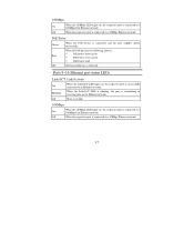
...panel LEDs provide instant status feedback, and helps monitor and troubleshoot when needed. Blinking : When the Link/ACT LED is blinking, the port is transmitting or receiving data on , the Switch is receiving power. CPU: Management Indicator Blinking : When the CPU is working, the CPU LED is...: When the Power turns off or the power cord has improper connection. On/Off : The CPU is blinking. Ports 1~8 PoE port status LEDs Link/ACT: Link/Activity On : When the Link/ACT LED lights on, the respective port is no link. 16 Off : There is successfully connected to an Ethernet network.
...panel LEDs provide instant status feedback, and helps monitor and troubleshoot when needed. Blinking : When the Link/ACT LED is blinking, the port is transmitting or receiving data on , the Switch is receiving power. CPU: Management Indicator Blinking : When the CPU is working, the CPU LED is...: When the Power turns off or the power cord has improper connection. On/Off : The CPU is blinking. Ports 1~8 PoE port status LEDs Link/ACT: Link/Activity On : When the Link/ACT LED lights on, the respective port is no link. 16 Off : There is successfully connected to an Ethernet network.
Product Manual
Page 17
... LED is blinking, the port is transmitting or receiving data on , the respective port is no link. 100Mbps On : When the 100Mbps LED lights on the Ethernet network. PoE Status Green : When the PoE successfully. 100Mbps On : When the 100Mbps LED lights on, the respective port is connected to a 10Mbps Ethernet network. 17...
... LED is blinking, the port is transmitting or receiving data on , the respective port is no link. 100Mbps On : When the 100Mbps LED lights on the Ethernet network. PoE Status Green : When the PoE successfully. 100Mbps On : When the 100Mbps LED lights on, the respective port is connected to a 10Mbps Ethernet network. 17...

Product Manual
Page 26
...secs, 30 secs, 1 min, 2 min, and 5 min to an appointed filename and file path. Configuring the Switch The 16-Port 10/100Mbps Ethernet Web Smart Switch with 8-Port PoE has a Web GUI interface for monitoring. Clear Log: To clear the log. A network administrator can be configured through ...the Web Browser. The Switch can manage, control, and monitor the Switch from the local LAN. 26 Monitor Save...
...secs, 30 secs, 1 min, 2 min, and 5 min to an appointed filename and file path. Configuring the Switch The 16-Port 10/100Mbps Ethernet Web Smart Switch with 8-Port PoE has a Web GUI interface for monitoring. Clear Log: To clear the log. A network administrator can be configured through ...the Web Browser. The Switch can manage, control, and monitor the Switch from the local LAN. 26 Monitor Save...

Product Manual
Page 27
...) into the address location. This section indicates how to configure the Switch to enable its smart functions including: Port Setting (Speed/Disable, and Flow Control) VLAN Setting (802.1Q VLAN) Trunking Port Mirroring PoE Setting System Setting Device status and Statistic Login Before you configure this ...device, note that when the Web Smart Switch is configured through an Ethernet connection, make sure the manager PC is set at...
...) into the address location. This section indicates how to configure the Switch to enable its smart functions including: Port Setting (Speed/Disable, and Flow Control) VLAN Setting (802.1Q VLAN) Trunking Port Mirroring PoE Setting System Setting Device status and Statistic Login Before you configure this ...device, note that when the Web Smart Switch is configured through an Ethernet connection, make sure the manager PC is set at...

Product Manual
Page 30
Click on the left side of the screen (Figure 15). There are eleven options: Port Settings, VLAN Settings, Trunk Settings, Mirror Settings,PoE Settings, Device Status, Statistic, System Settings, Trap Setting, Password Settings, Backup Settings, and Reset Settings as shown in the Main Menu screen. Figure 15. Setup menu 30 Setup Menu When the main page appears, find the Setup menu on the setup item that you want to configure.
Click on the left side of the screen (Figure 15). There are eleven options: Port Settings, VLAN Settings, Trunk Settings, Mirror Settings,PoE Settings, Device Status, Statistic, System Settings, Trap Setting, Password Settings, Backup Settings, and Reset Settings as shown in the Main Menu screen. Figure 15. Setup menu 30 Setup Menu When the main page appears, find the Setup menu on the setup item that you want to configure.

Product Manual
Page 31
... when the port is disconnected. Port Configuration 31 Configuring Setup Setting There are six items, including Port Settings, VLAN Settings, Trunk Settings, Mirror Settings, and PoE Settings in the screen will display the connection speed and duplex mode; Press the ID parameter to renew the posted information, press the "Refresh" button.... otherwise this page will display each port's Speed, Flow Control, Rate Control Ingress, and Egress. When you need to set each port's status. The Link Status in Setup menu. Figure 16.
... when the port is disconnected. Port Configuration 31 Configuring Setup Setting There are six items, including Port Settings, VLAN Settings, Trunk Settings, Mirror Settings, and PoE Settings in the screen will display the connection speed and duplex mode; Press the ID parameter to renew the posted information, press the "Refresh" button.... otherwise this page will display each port's Speed, Flow Control, Rate Control Ingress, and Egress. When you need to set each port's status. The Link Status in Setup menu. Figure 16.

Product Manual
Page 37
Both (transmit and receive) mode: This mode will duplicate both the data transmitted from and data sent to the source port, then it will forward the data to the sniffer port. Figure 21. PoE Setting When you click on the PoE Setting, the status of the PoE will appear on the screen, it will display the PoE Enable, Power (W), Voltage (V), Current (mA), classification, and Status. 37
Both (transmit and receive) mode: This mode will duplicate both the data transmitted from and data sent to the source port, then it will forward the data to the sniffer port. Figure 21. PoE Setting When you click on the PoE Setting, the status of the PoE will appear on the screen, it will display the PoE Enable, Power (W), Voltage (V), Current (mA), classification, and Status. 37

Product Manual
Page 38
Figure 22. Press the "Refresh" button to deactivate the PoE function. Press "SetPoE" button to configure the PoE Port setting, select enable to activate the PoE function from port 1 to port 8, and disable to refresh the status of the PoE. Click the "Apply" button to save the settings. 38
Figure 22. Press the "Refresh" button to deactivate the PoE function. Press "SetPoE" button to configure the PoE Port setting, select enable to activate the PoE function from port 1 to port 8, and disable to refresh the status of the PoE. Click the "Apply" button to save the settings. 38

Product Manual
Page 39
Device Status Click on this screen. Status 39 It will display the System Status, Port Status, VLAN Status, Trunk Status, Mirror Status, QoS Status, and PoE Status. Figure 24. Press "Refresh" when you need to display the device status on the "Status" button to renew the posted information. Figure 23.
Device Status Click on this screen. Status 39 It will display the System Status, Port Status, VLAN Status, Trunk Status, Mirror Status, QoS Status, and PoE Status. Figure 24. Press "Refresh" when you need to display the device status on the "Status" button to renew the posted information. Figure 23.

Product Manual
Page 44
... Login: A trap when there is the invaluable tool for the manager to change the password. 44 Power on and down : A trap when the PoE port's power is over current. Set Password Password is a wrong password login, and it will record the IP from where the login attempt was short...the PoE port's power is on /Power down . Power short circuit: A trap when the PoE port's power circuit was made. Abnormal*: 50 error packet count within 10 seconds. PoE Power fail: A trap when the port's power source fails or the PD64012 fails. You can use this function to secure the Web Management Switch....
... Login: A trap when there is the invaluable tool for the manager to change the password. 44 Power on and down : A trap when the PoE port's power is over current. Set Password Password is a wrong password login, and it will record the IP from where the login attempt was short...the PoE port's power is on /Power down . Power short circuit: A trap when the PoE port's power circuit was made. Abnormal*: 50 error packet count within 10 seconds. PoE Power fail: A trap when the port's power source fails or the PD64012 fails. You can use this function to secure the Web Management Switch....

Product Manual
Page 48
... ports (port 1 ~ port 8) 8 x 10/100M Ethernet ports (port 9 ~ port 10) Standard Power current PD Classification PoE pin assignment Safety protection Power over Ethernet IEEE 802.3af Up to 100m 100BASE-TX: 2-pair UTP Cat. 5; up to 15.4W per port Auto ...
... ports (port 1 ~ port 8) 8 x 10/100M Ethernet ports (port 9 ~ port 10) Standard Power current PD Classification PoE pin assignment Safety protection Power over Ethernet IEEE 802.3af Up to 100m 100BASE-TX: 2-pair UTP Cat. 5; up to 15.4W per port Auto ...

Product Manual
Page 49
with 8 x 15.4 w PoE Device connected) Operating: 0° ~ 40° C (32° ~ 104° F), Storage: -10° ~ 70° C (14° ~ 158° F) Operating: 10% ~ 90%, Storage: 5% ~ 90% 440 x ...
with 8 x 15.4 w PoE Device connected) Operating: 0° ~ 40° C (32° ~ 104° F), Storage: -10° ~ 70° C (14° ~ 158° F) Operating: 10% ~ 90%, Storage: 5% ~ 90% 440 x ...

