User Guide
Page 8
10/100 Fast Ethernet Switch User's Guide LED INDICATORS 16 4 CONNECTING THE SWITCH 18 PC TO SWITCH 18 HUB TO SWITCH 19 10Base-T Hub 20 100Base-TX Hub 20 HUB WITHOUT UPLINK (MDI-II) PORT 21 Using straight cable 21 Using crossover cable 21 SWITCH TO SWITCH (OTHER DEVICES 22 Using straight cable 22 Using crossover cable 22 5 TECHNICAL SPECIFICATIONS 25 6 RJ-45 PIN SPECIFICATION 28 7 INDEX...30 viii About This Guide
10/100 Fast Ethernet Switch User's Guide LED INDICATORS 16 4 CONNECTING THE SWITCH 18 PC TO SWITCH 18 HUB TO SWITCH 19 10Base-T Hub 20 100Base-TX Hub 20 HUB WITHOUT UPLINK (MDI-II) PORT 21 Using straight cable 21 Using crossover cable 21 SWITCH TO SWITCH (OTHER DEVICES 22 Using straight cable 22 Using crossover cable 22 5 TECHNICAL SPECIFICATIONS 25 6 RJ-45 PIN SPECIFICATION 28 7 INDEX...30 viii About This Guide
User Guide
Page 14
..., runts, etc. at 148,800 pps per port at 100% of wire-speed for any port. Performance features ♦ Store and forward switching scheme capability to support rate adaptation and ensures data integrity. ♦ N-way Auto-negotiation for 100Mbps speed. ♦ Data filtering rate eliminates...at 14,880 pps per port at 10/100 Mbps for uplink to another switch, hub or repeater. 10/100 Fast Ethernet Switch User's Guide The Switches are an unmanaged 10/100 Fast Ethernet Switch that if you are using the uplink port, you with automatic and flexible solutions in accelerating small ...
..., runts, etc. at 148,800 pps per port at 100% of wire-speed for any port. Performance features ♦ Store and forward switching scheme capability to support rate adaptation and ensures data integrity. ♦ N-way Auto-negotiation for 100Mbps speed. ♦ Data filtering rate eliminates...at 14,880 pps per port at 10/100 Mbps for uplink to another switch, hub or repeater. 10/100 Fast Ethernet Switch User's Guide The Switches are an unmanaged 10/100 Fast Ethernet Switch that if you are using the uplink port, you with automatic and flexible solutions in accelerating small ...
User Guide
Page 23
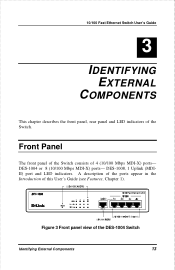
10/100 Fast Ethernet Switch User's Guide 3 3 IDENTIFYING EXTERNAL COMPONENTS This chapter describes the front panel, rear panel and LED indicators of 4 (10/100 Mbps MDI-X) ports- Front Panel The front panel of the Switch consists of the Switch. DES-1004 or 8 (10/100 Mbps MDI-X) ports- DES-1008, 1 Uplink (MDIII) port and LED indicators. A description of the ports appear in the Introduction of this User's Guide (see Features, Chapter 1). 0',0,, Figure 3 Front panel view of the DES-1004 Switch Identifying External Components 13
10/100 Fast Ethernet Switch User's Guide 3 3 IDENTIFYING EXTERNAL COMPONENTS This chapter describes the front panel, rear panel and LED indicators of 4 (10/100 Mbps MDI-X) ports- Front Panel The front panel of the Switch consists of the Switch. DES-1004 or 8 (10/100 Mbps MDI-X) ports- DES-1008, 1 Uplink (MDIII) port and LED indicators. A description of the ports appear in the Introduction of this User's Guide (see Features, Chapter 1). 0',0,, Figure 3 Front panel view of the DES-1004 Switch Identifying External Components 13
User Guide
Page 26
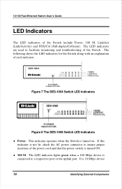
...the AC power connector to ensure proper insertion of the Switch include Power, 100 M, Link/Act (Link/Activity) and FDX/Col (Full-duplex/Collision). If a 10 Mbps device 16 Identifying External Components 10/100 Fast Ethernet Switch User's Guide LED Indicators The LED indicators of the ... for the Switch along with an explanation of the Switch. Figure 7 The DES-1004 Switch LED indicators Figure 8 The DES-1008 Switch LED indicators ♦ Power. The LED indicator lights green when a 100 Mbps device is turned on. The LED indicators are used to a respective port or the uplink port.
...the AC power connector to ensure proper insertion of the Switch include Power, 100 M, Link/Act (Link/Activity) and FDX/Col (Full-duplex/Collision). If a 10 Mbps device 16 Identifying External Components 10/100 Fast Ethernet Switch User's Guide LED Indicators The LED indicators of the ... for the Switch along with an explanation of the Switch. Figure 7 The DES-1004 Switch LED indicators Figure 8 The DES-1008 Switch LED indicators ♦ Power. The LED indicator lights green when a 100 Mbps device is turned on. The LED indicators are used to a respective port or the uplink port.
User Guide
Page 27
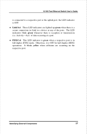
... Otherwise, it is reception or transmission (i.e. It blinks yellow when collisions are lighted up green when there is a secure connection (or link) to a respective port or the uplink port, the LED indicator is in full duplex (FDX) mode. This LED indicator is green when a respective port is OFF. ♦...; Link/Act. 10/100 Fast Ethernet Switch User's Guide is connected to a device at any of data occurring at a port. ♦ FDX/Col....
... Otherwise, it is reception or transmission (i.e. It blinks yellow when collisions are lighted up green when there is a secure connection (or link) to a respective port or the uplink port, the LED indicator is in full duplex (FDX) mode. This LED indicator is green when a respective port is OFF. ♦...; Link/Act. 10/100 Fast Ethernet Switch User's Guide is connected to a device at any of data occurring at a port. ♦ FDX/Col....
User Guide
Page 29
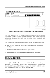
The Link/Act LED indicator illuminates upon LAN card capabilities. Hub to Switch A hub (10 or 100Base-T) can be connected to any of the Switch's (MDI-X) ports: 1x - 4x for the DES-1004 or 1x - 8x for the DES-1008. The connection is accomplished from the hub's uplink (MDI-II) port to the Switch via a two-pair Category...
The Link/Act LED indicator illuminates upon LAN card capabilities. Hub to Switch A hub (10 or 100Base-T) can be connected to any of the Switch's (MDI-X) ports: 1x - 4x for the DES-1004 or 1x - 8x for the DES-1008. The connection is accomplished from the hub's uplink (MDI-II) port to the Switch via a two-pair Category...
User Guide
Page 31
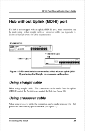
... Appendix A, Technical Specifications for cable requirements). Connecting The Switch 21 Figure 11 DES-1008 Switch connected to a Hub without Uplink (MDI-II) port If a hub is not equipped with an uplink (MDI-II) port, then connection can be made from the uplink (MDI-II) port of the Switch to any port of the Hub (see figure 11...
... Appendix A, Technical Specifications for cable requirements). Connecting The Switch 21 Figure 11 DES-1008 Switch connected to a Hub without Uplink (MDI-II) port If a hub is not equipped with an uplink (MDI-II) port, then connection can be made from the uplink (MDI-II) port of the Switch to any port of the Hub (see figure 11...
User Guide
Page 32
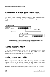
...connected ports are as follows: 22 Connecting The Switch Using crossover cable When using crossover cable, this is done from the uplink (MDI-II) port of the Switch (Switch A) to any of the 10 Mbps or 100 Mbps (MDI-X) port of the other switch (switch B) or other devices (see figure 12). Using..., etc.) via a two-pair Category 3, 4, 5 UTP/STP straight or crossover cable. 10/100M 10/100M Figure 12 DES-1008 Switch to switch connection using straight cable, this is done from any (MDI-X) port of the Switch (Switch A) to any of the 10 Mbps or 100 Mbps (MDI-X) port of the other...
...connected ports are as follows: 22 Connecting The Switch Using crossover cable When using crossover cable, this is done from the uplink (MDI-II) port of the Switch (Switch A) to any of the 10 Mbps or 100 Mbps (MDI-X) port of the other switch (switch B) or other devices (see figure 12). Using..., etc.) via a two-pair Category 3, 4, 5 UTP/STP straight or crossover cable. 10/100M 10/100M Figure 12 DES-1008 Switch to switch connection using straight cable, this is done from any (MDI-X) port of the Switch (Switch A) to any of the 10 Mbps or 100 Mbps (MDI-X) port of the other...

User Guide
Page 39
10/100 Fast Ethernet Switch User's Guide RJ-45 Connector pin assignment Contact Media Direct Interface Signal 1 Tx + (transmit) 2 Tx - (transmit) 3 Rx + (receive) 4 Not used 5 Not used 6 Rx - (receive) 7 Not used 8 Not used The standard Category 3 cable, RJ-45 pin assignment The following shows straight cable and crossover cable connection: Straight cable for Switch (uplink MDI-II port) to switch/Hub or other devices connection Crossover cable for Switch (MDI-X port) to switch/hub or other network devices (MDI-X port) connection RJ-45 Pin Specification 29
10/100 Fast Ethernet Switch User's Guide RJ-45 Connector pin assignment Contact Media Direct Interface Signal 1 Tx + (transmit) 2 Tx - (transmit) 3 Rx + (receive) 4 Not used 5 Not used 6 Rx - (receive) 7 Not used 8 Not used The standard Category 3 cable, RJ-45 pin assignment The following shows straight cable and crossover cable connection: Straight cable for Switch (uplink MDI-II port) to switch/Hub or other devices connection Crossover cable for Switch (MDI-X port) to switch/hub or other network devices (MDI-X port) connection RJ-45 Pin Specification 29
User Guide
Page 41
10/100 Fast Ethernet Switch User's Guide RAM Buffer 27 Rear Panel 14 RJ-45 Pin Specification 28 S segments 2 Setup 7 Storage Temperature 26 Store and forward 4 straight cable 29 switch 2 Switch to Switch (other devices)22 Switching LAN technology ........ 3 Switching Technology 2 System Fan 15 T Transmission Method 27 U Unpacking 6 Uplink/ MDI-II 4 V ventilation 7 W Wall Installation (DES-1004)..... 8 Weight 27 Index 31
10/100 Fast Ethernet Switch User's Guide RAM Buffer 27 Rear Panel 14 RJ-45 Pin Specification 28 S segments 2 Setup 7 Storage Temperature 26 Store and forward 4 straight cable 29 switch 2 Switch to Switch (other devices)22 Switching LAN technology ........ 3 Switching Technology 2 System Fan 15 T Transmission Method 27 U Unpacking 6 Uplink/ MDI-II 4 V ventilation 7 W Wall Installation (DES-1004)..... 8 Weight 27 Index 31