Operation Manual
Page 1
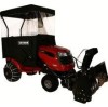
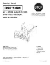
Sears, Roebuck and Co., Hoffman Estates, IL 60179 U.S.A. www sears.corn/craftsman PRINTED iN U.S.A. Operator's Manual CRQFTSNQ°N 42"= 2 STAGE SNOW THROWER TRACTOR ATTACHMENT Model No. 486.24838 DO NOT RETURN TO STORE For Missing Parts or Assembly Questions Call 1-866-576-8388 CAUTION: Before using this product, read this manual and follow all Safety Rules and Operating instructions. Safety Assembly Operation Maintenance Parts FORM NO. 49812 (2/06)
Sears, Roebuck and Co., Hoffman Estates, IL 60179 U.S.A. www sears.corn/craftsman PRINTED iN U.S.A. Operator's Manual CRQFTSNQ°N 42"= 2 STAGE SNOW THROWER TRACTOR ATTACHMENT Model No. 486.24838 DO NOT RETURN TO STORE For Missing Parts or Assembly Questions Call 1-866-576-8388 CAUTION: Before using this product, read this manual and follow all Safety Rules and Operating instructions. Safety Assembly Operation Maintenance Parts FORM NO. 49812 (2/06)
Operation Manual
Page 2
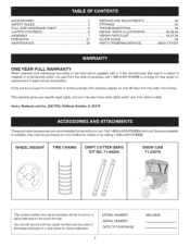
Tl_is warranty gives you specific legal rigl_ts, and you may be found on a decal attached to the snow thrower. If avaJlabJe, they are recommended for use with it, if this warranty applies for free repair (or replacement if repair proves impossible). Sears, Roebuck and ... may also have other accessories are available. WHEEL WEIGHT TiRE CHAINS DRIFT CUTTER BARS KIT NO. 71-88294 SNOW CAB 71-24276 The model number and serial numbers will be purchased at most Craftsman outlets or by calling 1-800-4-MY-HOME®. You should record both the serial number and the date...
Tl_is warranty gives you specific legal rigl_ts, and you may be found on a decal attached to the snow thrower. If avaJlabJe, they are recommended for use with it, if this warranty applies for free repair (or replacement if repair proves impossible). Sears, Roebuck and ... may also have other accessories are available. WHEEL WEIGHT TiRE CHAINS DRIFT CUTTER BARS KIT NO. 71-88294 SNOW CAB 71-24276 The model number and serial numbers will be purchased at most Craftsman outlets or by calling 1-800-4-MY-HOME®. You should record both the serial number and the date...
Operation Manual
Page 3
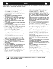
... and check for the cause Vibration is adjusted to operate the equipment without proper instruction. Do not use the snow thrower without good visibility or light aLloeortk!!foYr othuisr ssyamfebtyoltois pinovinotlvoeudt .important safety precautions It means -- Use extreme caution ...cabs etc.) Never operate the snow thrower without the rear weight attached to clear steep slopes. without wearing adequate winter outer garments * Wear substantial footwear which will be used on slopes Do not attempt to the tractor. Exercisecautionat alltimes,whenusingpowerequipment. Readthisowner'...
... and check for the cause Vibration is adjusted to operate the equipment without proper instruction. Do not use the snow thrower without good visibility or light aLloeortk!!foYr othuisr ssyamfebtyoltois pinovinotlvoeudt .important safety precautions It means -- Use extreme caution ...cabs etc.) Never operate the snow thrower without the rear weight attached to clear steep slopes. without wearing adequate winter outer garments * Wear substantial footwear which will be used on slopes Do not attempt to the tractor. Exercisecautionat alltimes,whenusingpowerequipment. Readthisowner'...
Operation Manual
Page 7
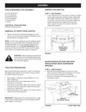
..." nylock nuts (CO) Refer to the Service and Adjustments section on page 29 CAUTION: Before starting to assemble the snow thrower, remove the spark plug wire(s), set the parking brake and remove the key from the tractor ignition TRACTOR PREPARATION Before performing these instructions, refer to the Service and Adjustments section of your particular...
..." nylock nuts (CO) Refer to the Service and Adjustments section on page 29 CAUTION: Before starting to assemble the snow thrower, remove the spark plug wire(s), set the parking brake and remove the key from the tractor ignition TRACTOR PREPARATION Before performing these instructions, refer to the Service and Adjustments section of your particular...
Operation Manual
Page 9
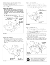
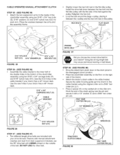
... the frame with the notches 1othe rear STEP 10: (SEE FIGURE 10) • Two different length drive belts are included with your snow thrower Tractors with manual attachment clutches and single front deck suspension brackets use the 56" drive belt with the flat side o1 the belt against the...BOLTS FIGURE 8 5/16" NYLOCK NUT (CC) \ 5/16" x 3/4" HEX BOLT (E) (#48138) 7' DRIVE BELT FIGURE 10 Did you select the correct drive belt fo_ your tractor? Place the bolt in the clutchddler assembly using two 5/16" x 3/4" hex bolts (E) and 5/16" nylock nuts (CC) for each arm Place the arms on the...
... the frame with the notches 1othe rear STEP 10: (SEE FIGURE 10) • Two different length drive belts are included with your snow thrower Tractors with manual attachment clutches and single front deck suspension brackets use the 56" drive belt with the flat side o1 the belt against the...BOLTS FIGURE 8 5/16" NYLOCK NUT (CC) \ 5/16" x 3/4" HEX BOLT (E) (#48138) 7' DRIVE BELT FIGURE 10 Did you select the correct drive belt fo_ your tractor? Place the bolt in the clutchddler assembly using two 5/16" x 3/4" hex bolts (E) and 5/16" nylock nuts (CC) for each arm Place the arms on the...
Operation Manual
Page 11
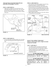
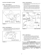
... link from the spring. THIS SECTION IS FOR TRACTORS WITH AN ELECTRIC ATTACHMENT CLUTCH STEP 14: (SEE FIGURE 14) Attach the two suspension arms to the rear of the clutch/idler assembly using two 5/16" x 3/4" hex bolts (E) and 5/16" nylock nuts (CO) for your snow thrower. SIDE) 1 LOCK NUT FIGURE 14 5/16" ... l CLUTECleHctTriYcPE 48", 54" Electric SPRING ATTACH SPRING HERE 5TH LINK CHAIN (L.N. Use the table below to select the correct drive belt for your type tractor The part number is printed on the outside of the belt Set aside the belt that is not for each arm Place the arms on...
... link from the spring. THIS SECTION IS FOR TRACTORS WITH AN ELECTRIC ATTACHMENT CLUTCH STEP 14: (SEE FIGURE 14) Attach the two suspension arms to the rear of the clutch/idler assembly using two 5/16" x 3/4" hex bolts (E) and 5/16" nylock nuts (CO) for your snow thrower. SIDE) 1 LOCK NUT FIGURE 14 5/16" ... l CLUTECleHctTriYcPE 48", 54" Electric SPRING ATTACH SPRING HERE 5TH LINK CHAIN (L.N. Use the table below to select the correct drive belt for your type tractor The part number is printed on the outside of the belt Set aside the belt that is not for each arm Place the arms on...
Operation Manual
Page 15
...(p. 19) Use the appropriate instructions for your tractor. DO NOT USE timeother belt • SlightEy _oosen the hex bolt next to the flat idler pulley Install the drive belt down ) position. • Screw the trunnion (11)onto the end of the snow thrower engagement rod. • Locate the c_utcl_arm (where... the mower clutch rod was connected) underneath the right hand side the tractor, iust to the inside of the belt against the pulley. Us{ng the wrong ...
...(p. 19) Use the appropriate instructions for your tractor. DO NOT USE timeother belt • SlightEy _oosen the hex bolt next to the flat idler pulley Install the drive belt down ) position. • Screw the trunnion (11)onto the end of the snow thrower engagement rod. • Locate the c_utcl_arm (where... the mower clutch rod was connected) underneath the right hand side the tractor, iust to the inside of the belt against the pulley. Us{ng the wrong ...

Operation Manual
Page 16
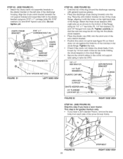
...with a pulley keeper that secure the keeper Attach the new pulley keeper supplied with the snow thrower, reusing the original bolt, washer and nut. NOTE: Some tractors may already be placed to the inside of the tractor frame• Lift the front of the engine pulley keeper or timekeeper bolt• •... that it 1o the RH and L.H hanger brackets using a rubber band tied to the engine pulley keeper * Attach the clutch/idler assembly to the tractor frame as shown when performing the next operation. ROD i / FIGURE 32 RIGHT SIDE VIEW STEP 83: (SEE FIGURE 33) • Make sure ...
...with a pulley keeper that secure the keeper Attach the new pulley keeper supplied with the snow thrower, reusing the original bolt, washer and nut. NOTE: Some tractors may already be placed to the inside of the tractor frame• Lift the front of the engine pulley keeper or timekeeper bolt• •... that it 1o the RH and L.H hanger brackets using a rubber band tied to the engine pulley keeper * Attach the clutch/idler assembly to the tractor frame as shown when performing the next operation. ROD i / FIGURE 32 RIGHT SIDE VIEW STEP 83: (SEE FIGURE 33) • Make sure ...
Operation Manual
Page 17
...the cable bracket using two 5/16" x 3/4" hex bolts (E), 5/16" washers (U) and 5/16" nylock nuts (CO) for your tractor has a 42" mower deck. Use the rear holes if your tractor has a 46" mower deck 5/16" x 3/4" CARRIAGE BOLT (O) ' __ CABLE (#46989) DRIVE BELT FIGURE 37 Did you choose...WASHER (T) 5/16" NYLOCK NUT (CC) FIGURE 36 STEP 37: (SEE FIGURE 37) • Two different length drive belts are included with your snow thrower Tractors with manual attachment clutcl_es and dual front deck suspension brackets use the 55" drive belt with the flat side o1 the belt against the puEley...
...the cable bracket using two 5/16" x 3/4" hex bolts (E), 5/16" washers (U) and 5/16" nylock nuts (CO) for your tractor has a 42" mower deck. Use the rear holes if your tractor has a 46" mower deck 5/16" x 3/4" CARRIAGE BOLT (O) ' __ CABLE (#46989) DRIVE BELT FIGURE 37 Did you choose...WASHER (T) 5/16" NYLOCK NUT (CC) FIGURE 36 STEP 37: (SEE FIGURE 37) • Two different length drive belts are included with your snow thrower Tractors with manual attachment clutcl_es and dual front deck suspension brackets use the 55" drive belt with the flat side o1 the belt against the puEley...

Operation Manual
Page 18
...engine pulley and then onto the large pulley on page 21. CLUTCH/IDLER ENGINE PULLEY KEEPER ASSEMBLY Le# Side of the tractor frame. Attach the clutch/idler assembly to the tractor frame as follows. Hook the assembly's notched arms onto the two shoulder bolts you assembled to the inside of the ...on top of the c_utch/idler assembly.The belt must be equipped with the snow thrower, reusing the original bolt, washer and nut. STEP 39: (SEE FIGURE 39) * Remove the engine pulley keeper from the side of the tractor frame by removing the washer and nut that secure the keeper Attach the new...
...engine pulley and then onto the large pulley on page 21. CLUTCH/IDLER ENGINE PULLEY KEEPER ASSEMBLY Le# Side of the tractor frame. Attach the clutch/idler assembly to the tractor frame as follows. Hook the assembly's notched arms onto the two shoulder bolts you assembled to the inside of the ...on top of the c_utch/idler assembly.The belt must be equipped with the snow thrower, reusing the original bolt, washer and nut. STEP 39: (SEE FIGURE 39) * Remove the engine pulley keeper from the side of the tractor frame by removing the washer and nut that secure the keeper Attach the new...
Operation Manual
Page 19
... OF BOTTOM _- _ / LEFT FRONT HOLE FIGURE 42 TENSIONING CHAIN (PP) STEP 44: (SEE TABLE 2) Two different length drive belts are included with your snow thrower• Use the table below to select the correct drive belt for your type tractor The part number is printed on the outside of ... HERE SPRING 5TH LINK CHAIN (LH. Attach a 3/32" hairpin cotter (LL) to the chain, placing it 55" CELT (PART #46989) TRACTOR TYPE DECK SiZE j_ CLUTCH TYPE (LT) Lawn Tractor 38", 42", 46" _ Electric 56" BELT (PART #48188) T(LRTA) CLTaOwnR TTraYcPtoEr TABLE 2 DEC4K8"SIZE _ CLUTECleHctriTcYPE 19
... OF BOTTOM _- _ / LEFT FRONT HOLE FIGURE 42 TENSIONING CHAIN (PP) STEP 44: (SEE TABLE 2) Two different length drive belts are included with your snow thrower• Use the table below to select the correct drive belt for your type tractor The part number is printed on the outside of ... HERE SPRING 5TH LINK CHAIN (LH. Attach a 3/32" hairpin cotter (LL) to the chain, placing it 55" CELT (PART #46989) TRACTOR TYPE DECK SiZE j_ CLUTCH TYPE (LT) Lawn Tractor 38", 42", 46" _ Electric 56" BELT (PART #48188) T(LRTA) CLTaOwnR TTraYcPtoEr TABLE 2 DEC4K8"SIZE _ CLUTECleHctriTcYPE 19

Operation Manual
Page 21
... of the cable wire into the hole in the lift rod Place the threaded fitting into the lift bracket on the right side of the snow thrower. HINT: For easier assembly of the discharge housing using two 5/16" x 1-1/4" carriage bolts (M), and 5/16" Nylock nuts (CO). Refer also to the... the cable wire. Fasten the handle to the bracket on page 29 in this manual. LIFT HANDLE \, STEP 50: (SEE FIGURE 49) • Tilt the snow thrower back down into the locked position. DISCHARGE HOUSING _, ', X, ,\ 5/16" NYLOCK NUT (CC) FIGURE 47 5/16" x 1-3/4" HEX BOLT (D) LIFT BRACKET RIGHT SIDE VIEW ...
... of the cable wire into the hole in the lift rod Place the threaded fitting into the lift bracket on the right side of the snow thrower. HINT: For easier assembly of the discharge housing using two 5/16" x 1-1/4" carriage bolts (M), and 5/16" Nylock nuts (CO). Refer also to the... the cable wire. Fasten the handle to the bracket on page 29 in this manual. LIFT HANDLE \, STEP 50: (SEE FIGURE 49) • Tilt the snow thrower back down into the locked position. DISCHARGE HOUSING _, ', X, ,\ 5/16" NYLOCK NUT (CC) FIGURE 47 5/16" x 1-3/4" HEX BOLT (D) LIFT BRACKET RIGHT SIDE VIEW ...
Operation Manual
Page 22
... nuts (CO) Do not tighten yet, •\ CHUTE CRANK 5/16" x 1" BRACKET CHUTE CRANK -- If not, loosen by 1/4 turn each side o1 the snow thrower frame• FIGURE 53 22 STOP BOLT RIGHT SIDE ViEW Tighten carefully so that timenuts are snug but do not dig into the plastic chute... and 1/4" flanged lock nuts (Z). I/4"FLANGED LOCK NUT (Z) /_. \\\ _\ FIGURE 52 RIGHT SiDE ViEW STEP 54: (SEE FIGURE 53) Skip this step if you have a lawn tractor. STEP 52: (SEE FIGURE 51) • Attach the chute crank rod assembly brackets to the plastic bracket on the left side of the flange Attach...
... nuts (CO) Do not tighten yet, •\ CHUTE CRANK 5/16" x 1" BRACKET CHUTE CRANK -- If not, loosen by 1/4 turn each side o1 the snow thrower frame• FIGURE 53 22 STOP BOLT RIGHT SIDE ViEW Tighten carefully so that timenuts are snug but do not dig into the plastic chute... and 1/4" flanged lock nuts (Z). I/4"FLANGED LOCK NUT (Z) /_. \\\ _\ FIGURE 52 RIGHT SiDE ViEW STEP 54: (SEE FIGURE 53) Skip this step if you have a lawn tractor. STEP 52: (SEE FIGURE 51) • Attach the chute crank rod assembly brackets to the plastic bracket on the left side of the flange Attach...

Operation Manual
Page 23
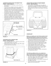
...idler arm. Make sure the belt passes over the top of the tractor. ATTACHING SNOW THROWER TO TRACTOR NOTE: An additional person's help may be required to mount the snow thrower to the front of the large drive pulley and underneath the two...snow thrower. * Remove the Attachment Pin from the snow thrower. * Extend the auger belt out behind the snow thrower, making sure the belt is still fooped over the top of the snow thrower by lifting up behind the snow thrower, centering it between the two pulleys on the snow thrower housing. STEP 58: (SEE FIGURE 84) * Place the tractor and snow thrower...
...idler arm. Make sure the belt passes over the top of the tractor. ATTACHING SNOW THROWER TO TRACTOR NOTE: An additional person's help may be required to mount the snow thrower to the front of the large drive pulley and underneath the two...snow thrower. * Remove the Attachment Pin from the snow thrower. * Extend the auger belt out behind the snow thrower, making sure the belt is still fooped over the top of the snow thrower by lifting up behind the snow thrower, centering it between the two pulleys on the snow thrower housing. STEP 58: (SEE FIGURE 84) * Place the tractor and snow thrower...
Operation Manual
Page 26
...hole in the cross brace. / ! ALTERNATE INSTRUCTIONS FOR WEIGRTTRAY STEP 83: (SEE FIGURE 61) Block up the rea_ of the tractor to help enhance the performance of your snow thrower. • Make sure air assembly instructions have been completed with aH bolts and nuts properly tightened. • Make sure the ... notched end of each side brace to the top hole in the each side of the tractor frame, using a 3/8-18 x 1" slotted truss head bolt (J) for each brace * Assemble the weight tray to the side braces as the shape of the fender will obtain the best performance from your snow thrower.
...hole in the cross brace. / ! ALTERNATE INSTRUCTIONS FOR WEIGRTTRAY STEP 83: (SEE FIGURE 61) Block up the rea_ of the tractor to help enhance the performance of your snow thrower. • Make sure air assembly instructions have been completed with aH bolts and nuts properly tightened. • Make sure the ... notched end of each side brace to the top hole in the each side of the tractor frame, using a 3/8-18 x 1" slotted truss head bolt (J) for each brace * Assemble the weight tray to the side braces as the shape of the fender will obtain the best performance from your snow thrower.
Operation Manual
Page 27
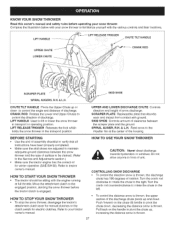
...handle to pivot the chute up and down , decreasing the distance snow is thrown 27 CONTROLLING SNOW DISCHARGE To control the direction snow is engaged HOWTO STOP YOUR SNOW THROWER * To stop the snow thrower, disengage the tractor's attachment cEutch ]ever for manual clutches or the clutch switch for... RELEASE TRIGGER CHUTE TILT HANDLE 3RANK ROD f SCRAPER PLATE /j SPIRAL AUGERS, R.H.& L.H. KNOW YOUR SNOW THROWER Read this owner's manual and safety rules before the tractor clutch is thrown, the discharge chute has 180 degrees of rotation Turn the crank rod clockwise to rotate...
...handle to pivot the chute up and down , decreasing the distance snow is thrown 27 CONTROLLING SNOW DISCHARGE To control the direction snow is engaged HOWTO STOP YOUR SNOW THROWER * To stop the snow thrower, disengage the tractor's attachment cEutch ]ever for manual clutches or the clutch switch for... RELEASE TRIGGER CHUTE TILT HANDLE 3RANK ROD f SCRAPER PLATE /j SPIRAL AUGERS, R.H.& L.H. KNOW YOUR SNOW THROWER Read this owner's manual and safety rules before the tractor clutch is thrown, the discharge chute has 180 degrees of rotation Turn the crank rod clockwise to rotate...
Operation Manual
Page 28
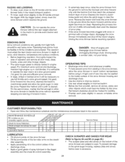
...Cleaning Lubrication Section _'__ I 11 Service Dates ! ' tI lI it A light coat of wax may also be applied to the inside surface of the snow thrower housing and discharge chute. • Use tire chains to reach outdoor temperature before wear is advisable to wear. To prevent damage to the spiral auger... housing, replace plate and shoes before using it II It LUBRICATION • Oil aH pivot points on the snow thrower. • Oil the pivot points of the two idler arms on the clutcW idler assembly • Apply penetrating oil to the control cables of ...
...Cleaning Lubrication Section _'__ I 11 Service Dates ! ' tI lI it A light coat of wax may also be applied to the inside surface of the snow thrower housing and discharge chute. • Use tire chains to reach outdoor temperature before wear is advisable to wear. To prevent damage to the spiral auger... housing, replace plate and shoes before using it II It LUBRICATION • Oil aH pivot points on the snow thrower. • Oil the pivot points of the two idler arms on the clutcW idler assembly • Apply penetrating oil to the control cables of ...
Operation Manual
Page 29
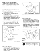
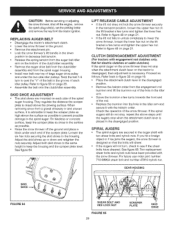
... into the hole in the groove of each side of the snow thrower If the spiral augers still do not stop when the attachment clutch lever on the tractor is disengaged, then adjustment is advisable to keep the scraper plate...thesnowthrowesr hutofftheenginer,emove thesparkplugwire(s)s,ettheparkingbrake andr_movtehekeyfromthetractoirgnition. REPLACING AUGER BELT • Disengage the tractor's attachment clutch. • Lower the snow thrower to the ground. • Remove the attachment pin • Lock the snow thrower's lift handle in the transport position, loosen the upper hex nut on ...
... into the hole in the groove of each side of the snow thrower If the spiral augers still do not stop when the attachment clutch lever on the tractor is disengaged, then adjustment is advisable to keep the scraper plate...thesnowthrowesr hutofftheenginer,emove thesparkplugwire(s)s,ettheparkingbrake andr_movtehekeyfromthetractoirgnition. REPLACING AUGER BELT • Disengage the tractor's attachment clutch. • Lower the snow thrower to the ground. • Remove the attachment pin • Lock the snow thrower's lift handle in the transport position, loosen the upper hex nut on ...
Operation Manual
Page 30
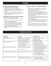
... off any salt deposit which may be left attached to be painted or coated with the snow thrower 1 Object jammed in spiral auger 2 Hard or heavy snow Front wheels slide instead of the tractor PARTS TO REMOVE AT END OF SEASON Remove the clutch/idler assembly (The two hanger brackets...of the clutchddler assembly. * Remove the auger ddve belt from the clutch/idler assembly See figure 56 on front wheels Snow thrower rides up over snow 1 Tractor ground speed too fast 2 Bottom snow is icy or hard packed 1 Reduce ground speed 2 Lower the skid shoes so that has become exposed should be ...
... off any salt deposit which may be left attached to be painted or coated with the snow thrower 1 Object jammed in spiral auger 2 Hard or heavy snow Front wheels slide instead of the tractor PARTS TO REMOVE AT END OF SEASON Remove the clutch/idler assembly (The two hanger brackets...of the clutchddler assembly. * Remove the auger ddve belt from the clutch/idler assembly See figure 56 on front wheels Snow thrower rides up over snow 1 Tractor ground speed too fast 2 Bottom snow is icy or hard packed 1 Reduce ground speed 2 Lower the skid shoes so that has become exposed should be ...


