Operation Manual
Page 1
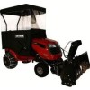
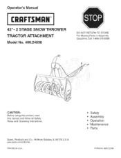
Sears, Roebuck and Co., Hoffman Estates, IL 60179 U.S.A. Safety Assembly Operation Maintenance Parts FORM NO. 49812 (2/06) www sears.corn/craftsman PRINTED iN U.S.A. Operator's Manual CRQFTSNQ°N 42"= 2 STAGE SNOW THROWER TRACTOR ATTACHMENT Model No. 486.24838 DO NOT RETURN TO STORE For Missing Parts or Assembly Questions Call 1-866-576-8388 CAUTION: Before using this product, read this manual and follow all Safety Rules and Operating instructions.
Sears, Roebuck and Co., Hoffman Estates, IL 60179 U.S.A. Safety Assembly Operation Maintenance Parts FORM NO. 49812 (2/06) www sears.corn/craftsman PRINTED iN U.S.A. Operator's Manual CRQFTSNQ°N 42"= 2 STAGE SNOW THROWER TRACTOR ATTACHMENT Model No. 486.24838 DO NOT RETURN TO STORE For Missing Parts or Assembly Questions Call 1-866-576-8388 CAUTION: Before using this product, read this manual and follow all Safety Rules and Operating instructions.
Operation Manual
Page 2
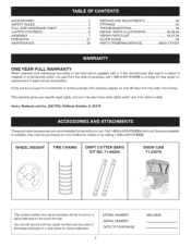
WHEEL WEIGHT TiRE CHAINS DRIFT CUTTER BARS KIT NO. 71-88294 SNOW CAB 71-24276 The model number and serial numbers will be purchased at most Craftsman outlets or by calling 1-800-4-MY-HOME®. If this product is used for commercial or rental purposes, this Snowthrower fails due to a defect ...only 90 days from the date of purchase. Tl_is warranty gives you specific legal rigl_ts, and you may be found on a decal attached to the snow thrower. Sears, Roebuck and Co., D817WA, Hoffm_n Estates, IL 60179 These and other rights which vary from state to arrange for free repair (or ...
WHEEL WEIGHT TiRE CHAINS DRIFT CUTTER BARS KIT NO. 71-88294 SNOW CAB 71-24276 The model number and serial numbers will be purchased at most Craftsman outlets or by calling 1-800-4-MY-HOME®. If this product is used for commercial or rental purposes, this Snowthrower fails due to a defect ...only 90 days from the date of purchase. Tl_is warranty gives you specific legal rigl_ts, and you may be found on a decal attached to the snow thrower. Sears, Roebuck and Co., D817WA, Hoffm_n Estates, IL 60179 These and other rights which vary from state to arrange for free repair (or ...
Operation Manual
Page 3
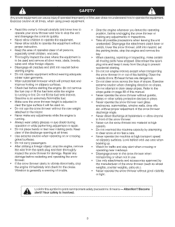
... speeds. Make sure the snow thrower height is an extremely flammable fuel. Do not place hands or feet near glass enclosures, automobiles, window wells, drop offs etc. Use extreme caution when operating on slopes Do not attempt to the tractor. without proper adiustment of ...alltimes,whenusingpowerequipment. Do not use care when backing up • Watch for the cause Vibration is generally a warning of the snow thrower discharge angle Never direct discharge at all persons, especially small children, and pets Thoroughly inspect the area where the equipment is running...
... speeds. Make sure the snow thrower height is an extremely flammable fuel. Do not place hands or feet near glass enclosures, automobiles, window wells, drop offs etc. Use extreme caution when operating on slopes Do not attempt to the tractor. without proper adiustment of ...alltimes,whenusingpowerequipment. Do not use care when backing up • Watch for the cause Vibration is generally a warning of the snow thrower discharge angle Never direct discharge at all persons, especially small children, and pets Thoroughly inspect the area where the equipment is running...
Operation Manual
Page 7
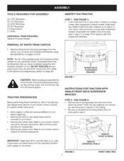
... 5/16" nylock nuts (CO) Refer to the Service and Adjustments section on page 29 CAUTION: Before starting to assemble the snow thrower, remove the spark plug wire(s), set the parking brake and remove the key from the tractor ignition TRACTOR PREPARATION Before performing these instructions, refer to the Service and Adjustments section of your...
... 5/16" nylock nuts (CO) Refer to the Service and Adjustments section on page 29 CAUTION: Before starting to assemble the snow thrower, remove the spark plug wire(s), set the parking brake and remove the key from the tractor ignition TRACTOR PREPARATION Before performing these instructions, refer to the Service and Adjustments section of your...
Operation Manual
Page 9
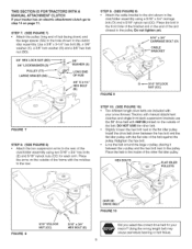
... with the notches 1othe rear STEP 10: (SEE FIGURE 10) • Two different length drive belts are included with your snow thrower Tractors with manual attachment clutches and single front deck suspension brackets use the 56" drive belt with the flat side o1 the belt ... BOLTS FIGURE 8 5/16" NYLOCK NUT (CC) \ 5/16" x 3/4" HEX BOLT (E) (#48138) 7' DRIVE BELT FIGURE 10 Did you select the correct drive belt fo_ your tractor has an electric attachment clutch go to the slot shown in the dutch/ idler assembly Use a 3/8" x 3-1/4" hex bolt (B), a 3/8" washer (X), a 3/8" lock washer (S) and...
... with the notches 1othe rear STEP 10: (SEE FIGURE 10) • Two different length drive belts are included with your snow thrower Tractors with manual attachment clutches and single front deck suspension brackets use the 56" drive belt with the flat side o1 the belt ... BOLTS FIGURE 8 5/16" NYLOCK NUT (CC) \ 5/16" x 3/4" HEX BOLT (E) (#48138) 7' DRIVE BELT FIGURE 10 Did you select the correct drive belt fo_ your tractor has an electric attachment clutch go to the slot shown in the dutch/ idler assembly Use a 3/8" x 3-1/4" hex bolt (B), a 3/8" washer (X), a 3/8" lock washer (S) and...
Operation Manual
Page 11
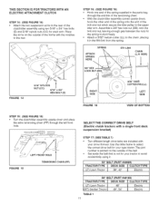
...in the parts bag through the left front hole. Use the table below to select the correct drive belt for your type tractor The part number is printed on the outside of the belt Set aside the belt that is not for the spring to ... TTraYcPtoEr t DE3C8K", 4S2iZ" E ][ CLUTECleHctriTcYPE 56" BELT (PART #48138) T(LRTA) CLTaOwRn TTraYcPtoEr (GT) Garden Tractor TABLE 1 11 DECK48"SIZE l CLUTECleHctTriYcPE 48", 54" Electric Assemble a 3/8" hex lock nut (DD) onto the bolt and nut, leaving enough gap between the nuts for your snow thrower. SPRING ATTACH SPRING HERE 5TH LINK CHAIN (L.N.
...in the parts bag through the left front hole. Use the table below to select the correct drive belt for your type tractor The part number is printed on the outside of the belt Set aside the belt that is not for the spring to ... TTraYcPtoEr t DE3C8K", 4S2iZ" E ][ CLUTECleHctriTcYPE 56" BELT (PART #48138) T(LRTA) CLTaOwRn TTraYcPtoEr (GT) Garden Tractor TABLE 1 11 DECK48"SIZE l CLUTECleHctTriYcPE 48", 54" Electric Assemble a 3/8" hex lock nut (DD) onto the bolt and nut, leaving enough gap between the nuts for your snow thrower. SPRING ATTACH SPRING HERE 5TH LINK CHAIN (L.N.
Operation Manual
Page 15
...drive belts are either rod operated (p 15), cable operated (p. 17) or electric (p. 19) Use the appropriate instructions for your snow thrower. Tractors with manual attachment clutches and dual front deck suspension brackets use the 55" drive belt with attachment clutches that are included with your...disengaged (down) position. • Screw the trunnion (11)onto the end of the snow thrower engagement rod. • Locate the c_utcl_arm (where the mower clutch rod was connected) underneath the right hand side the tractor, iust to the inside of the clutch/idler assembly using two 5/16" x 3/4"...
...drive belts are either rod operated (p 15), cable operated (p. 17) or electric (p. 19) Use the appropriate instructions for your snow thrower. Tractors with manual attachment clutches and dual front deck suspension brackets use the 55" drive belt with attachment clutches that are included with your...disengaged (down) position. • Screw the trunnion (11)onto the end of the snow thrower engagement rod. • Locate the c_utcl_arm (where the mower clutch rod was connected) underneath the right hand side the tractor, iust to the inside of the clutch/idler assembly using two 5/16" x 3/4"...

Operation Manual
Page 16
... to the slot using the 3/8" thin washer (W) and a 5/64" hairpin cotter (JJ) • Remove the engine pulley keeper from the side of the tractor frame by removing the washer and nut that it 1o the RH and L.H hanger brackets using a rubber band tied to the engine pulley keeper * Attach... dash panel is identical to the tractor frame as follows. The belt must be equipped with a pulley keeper that is in the disengaged (down) position • Pivot the upper idler arm so that secure the keeper Attach the new pulley keeper supplied with the snow thrower, reusing the original bolt, washer...
... to the slot using the 3/8" thin washer (W) and a 5/64" hairpin cotter (JJ) • Remove the engine pulley keeper from the side of the tractor frame by removing the washer and nut that it 1o the RH and L.H hanger brackets using a rubber band tied to the engine pulley keeper * Attach... dash panel is identical to the tractor frame as follows. The belt must be equipped with a pulley keeper that is in the disengaged (down) position • Pivot the upper idler arm so that secure the keeper Attach the new pulley keeper supplied with the snow thrower, reusing the original bolt, washer...
Operation Manual
Page 17
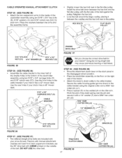
... cotter pin (JJ) • Place a spacer (ll) on the welded pin on the outside of the tractor. , Attach the tractor's clutch cable to the cable bracket Secure the cable housing guide (groove down between the arms and the assembly frame...; Assemble the cable bracket to the inner half of the double holes in the cable bracket if your snow thrower Tractors with manual attachment clutcl_es and dual front deck suspension brackets use the 55" drive belt with the flat ...FIGURE 36 STEP 37: (SEE FIGURE 37) • Two different length drive belts are included with your tractor has a 42" mower deck.
... cotter pin (JJ) • Place a spacer (ll) on the welded pin on the outside of the tractor. , Attach the tractor's clutch cable to the cable bracket Secure the cable housing guide (groove down between the arms and the assembly frame...; Assemble the cable bracket to the inner half of the double holes in the cable bracket if your snow thrower Tractors with manual attachment clutcl_es and dual front deck suspension brackets use the 55" drive belt with the flat ...FIGURE 36 STEP 37: (SEE FIGURE 37) • Two different length drive belts are included with your tractor has a 42" mower deck.

Operation Manual
Page 18
...engine pulley keeper, the idler pulley and the keeper bolt located beside the large pulley IMPORTANT: Do Not assemb}e the "V" belt around the outside of Tractor PULLEY / \\ FIGURE 89 / N FIGURE 40 VIEWED FROM UNDERNEATH 18 Lift the front of the assembly and attach it to the new one supplied.... • Go to the tractor frame as follows. Attach the clutch/idler assembly to step 48 on top of the c_utch/idler assembly.The belt must be equipped with a pulley keeper that secure the keeper Attach the new pulley keeper supplied with the snow thrower, reusing the original bolt, washer...
...engine pulley keeper, the idler pulley and the keeper bolt located beside the large pulley IMPORTANT: Do Not assemb}e the "V" belt around the outside of Tractor PULLEY / \\ FIGURE 89 / N FIGURE 40 VIEWED FROM UNDERNEATH 18 Lift the front of the assembly and attach it to the new one supplied.... • Go to the tractor frame as follows. Attach the clutch/idler assembly to step 48 on top of the c_utch/idler assembly.The belt must be equipped with a pulley keeper that secure the keeper Attach the new pulley keeper supplied with the snow thrower, reusing the original bolt, washer...
Operation Manual
Page 19
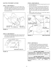
... OF BOTTOM _- _ / LEFT FRONT HOLE FIGURE 42 TENSIONING CHAIN (PP) STEP 44: (SEE TABLE 2) Two different length drive belts are included with your snow thrower• Use the table below to select the correct drive belt for your type tractor The part number is printed on the outside of ...Hook the other end of the spring onto the bottom of the clutch/idler assembly using it 55" CELT (PART #46989) TRACTOR TYPE DECK SiZE j_ CLUTCH TYPE (LT) Lawn Tractor 38", 42", 46" _ Electric 56" BELT (PART #48188) T(LRTA) CLTaOwnR TTraYcPtoEr TABLE 2 DEC4K8"SIZE _ CLUTECleHctriTcYPE 19 Place the...
... OF BOTTOM _- _ / LEFT FRONT HOLE FIGURE 42 TENSIONING CHAIN (PP) STEP 44: (SEE TABLE 2) Two different length drive belts are included with your snow thrower• Use the table below to select the correct drive belt for your type tractor The part number is printed on the outside of ...Hook the other end of the spring onto the bottom of the clutch/idler assembly using it 55" CELT (PART #46989) TRACTOR TYPE DECK SiZE j_ CLUTCH TYPE (LT) Lawn Tractor 38", 42", 46" _ Electric 56" BELT (PART #48188) T(LRTA) CLTaOwnR TTraYcPtoEr TABLE 2 DEC4K8"SIZE _ CLUTECleHctriTcYPE 19 Place the...

Operation Manual
Page 21
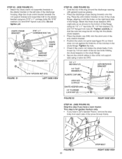
... rod support tube. • Assemble the crank rod support tube to the bracket on the left side of the lift release cable, tilt the snow thrower forward onto the spiral auger •• CRANK ROD 5t16" NYLOCK NUT (CC) .SUPPORT TUBE FIGURE 49 LEFT SIDE ViEW STEP 51: (...top side ot the crank support tube using two 5/16" X 1-3/4" he× bolts (D) and 5/16" Ny[ock nuts (CO). Insert the end of the snow thrower. CONTROL ASSTEILMTBLY "_ LEFT SIDEVIEW FIGURE 48 RIGHT SIDE VIEW 21 HINT: For easier assembly of the discharge housing using two 5/16" x 1-1/4" carriage bolts (M), and...
... rod support tube. • Assemble the crank rod support tube to the bracket on the left side of the lift release cable, tilt the snow thrower forward onto the spiral auger •• CRANK ROD 5t16" NYLOCK NUT (CC) .SUPPORT TUBE FIGURE 49 LEFT SIDE ViEW STEP 51: (...top side ot the crank support tube using two 5/16" X 1-3/4" he× bolts (D) and 5/16" Ny[ock nuts (CO). Insert the end of the snow thrower. CONTROL ASSTEILMTBLY "_ LEFT SIDEVIEW FIGURE 48 RIGHT SIDE VIEW 21 HINT: For easier assembly of the discharge housing using two 5/16" x 1-1/4" carriage bolts (M), and...
Operation Manual
Page 22
If not, loosen by 1/4 turn each side o1 the snow thrower frame• FIGURE 53 22 STOP BOLT RIGHT SIDE ViEW STEP 52: (SEE FIGURE 51) • Attach the chute crank rod assembly brackets to the ... (F), 1/4" fiat washers (T) and 1/4" flanged lock nuts (Z). I/4"FLANGED LOCK NUT (Z) /_. \\\ _\ FIGURE 52 RIGHT SiDE ViEW STEP 54: (SEE FIGURE 53) Skip this step if you have a lawn tractor. ROD ROD % / / BRACKET FIGURE 51 LEFT 81DEVIEW STEP 58: (SEE FIGURE 52) Coat the top of the ring around the discharge opening with general purpose...
If not, loosen by 1/4 turn each side o1 the snow thrower frame• FIGURE 53 22 STOP BOLT RIGHT SIDE ViEW STEP 52: (SEE FIGURE 51) • Attach the chute crank rod assembly brackets to the ... (F), 1/4" fiat washers (T) and 1/4" flanged lock nuts (Z). I/4"FLANGED LOCK NUT (Z) /_. \\\ _\ FIGURE 52 RIGHT SiDE ViEW STEP 54: (SEE FIGURE 53) Skip this step if you have a lawn tractor. ROD ROD % / / BRACKET FIGURE 51 LEFT 81DEVIEW STEP 58: (SEE FIGURE 52) Coat the top of the ring around the discharge opening with general purpose...

Operation Manual
Page 23
... the top of the belt must mate with the shoulder bolts in the grooves of all three pulleys. * Roll the tractor up behind the snow thrower, making sure the belt is still fooped over the top of the pulleys. The "V" side of the belt must be... the 1/8" hairpin cotter (KK) that the tractor can be rolled forward to attach the snow thrower. * Remove the Attachment Pin from the snow thrower. * Extend the auger belt out behind the snow thrower, centering it between the two pulleys on the snow thrower housing. ATTACHING SNOW THROWER TO TRACTOR NOTE: An additional person's help may be ...
... the top of the belt must mate with the shoulder bolts in the grooves of all three pulleys. * Roll the tractor up behind the snow thrower, making sure the belt is still fooped over the top of the pulleys. The "V" side of the belt must be... the 1/8" hairpin cotter (KK) that the tractor can be rolled forward to attach the snow thrower. * Remove the Attachment Pin from the snow thrower. * Extend the auger belt out behind the snow thrower, centering it between the two pulleys on the snow thrower housing. ATTACHING SNOW THROWER TO TRACTOR NOTE: An additional person's help may be ...
Operation Manual
Page 26
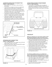
...STRAP (FF) The following checklist to help ensure that you operate your snow thrower, please review the following additional items are routed properly around pulleys and inside all other parts which were removed DOLE WITH HEX BO_HEMOVED t TRACTOR HITCH FIGURE 81 3/8" x 1" SLOTTED mUSS HEAD DOLT (J) SQUARE KEY...shape of the fender will obtain the best performance from your snow thrower. of dry sand. * Secure the keg with approximately 75 Ibs. ALTERNATE INSTRUCTIONS FOR WEIGRTTRAY STEP 83: (SEE FIGURE 61) Block up the rea_ of the tractor to allow . \ FIGURE 63 REAR REFLECTORS (QQ) ...
...STRAP (FF) The following checklist to help ensure that you operate your snow thrower, please review the following additional items are routed properly around pulleys and inside all other parts which were removed DOLE WITH HEX BO_HEMOVED t TRACTOR HITCH FIGURE 81 3/8" x 1" SLOTTED mUSS HEAD DOLT (J) SQUARE KEY...shape of the fender will obtain the best performance from your snow thrower. of dry sand. * Secure the keg with approximately 75 Ibs. ALTERNATE INSTRUCTIONS FOR WEIGRTTRAY STEP 83: (SEE FIGURE 61) Block up the rea_ of the tractor to allow . \ FIGURE 63 REAR REFLECTORS (QQ) ...
Operation Manual
Page 27
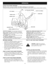
.... (Refer to the Service and Adjustments section ) * Make sure the tractor engine has the correct oil for electdc clutches Refer to your tractor owner's manual HOW TO USE YOUR SNOW THROWER CAUTION: Never direct discharge towards bystanders or windows Do not allow anyone in...to lift or lower the snow thrower to be sitting with the various controls and their locations. KNOW YOUR SNOW THROWER Read this owner's manual and safety rules before the tractor clutch is engaged HOWTO STOP YOUR SNOW THROWER * To stop the snow thrower, disengage the tractor's attachment cEutch ]ever for ...
.... (Refer to the Service and Adjustments section ) * Make sure the tractor engine has the correct oil for electdc clutches Refer to your tractor owner's manual HOW TO USE YOUR SNOW THROWER CAUTION: Never direct discharge towards bystanders or windows Do not allow anyone in...to lift or lower the snow thrower to be sitting with the various controls and their locations. KNOW YOUR SNOW THROWER Read this owner's manual and safety rules before the tractor clutch is engaged HOWTO STOP YOUR SNOW THROWER * To stop the snow thrower, disengage the tractor's attachment cEutch ]ever for ...
Operation Manual
Page 28
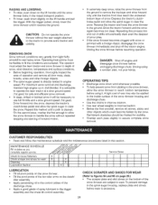
... Lubrication Section _'__ I 11 Service Dates ! ' tI lI it II It LUBRICATION • Oil aH pivot points on the snow thrower. • Oil the pivot points of the two idler arms on the clutcW idler assembly • Apply penetrating oil to the ...(Refer to figures 64 and 65 on page 29.) • The scraper plate and skid shoes on the bottom of the snow thrower are subject to operatethelawntractorata slowgroundspeed (1st gear)forsafeandefficienst nowremoval. • Indeep,driftedor bankedsnowit willbenecessaryto usefullthrottleanda slowgroundspeed(1stgear). CAUTION: Donotoperatethesnow throwewr...
... Lubrication Section _'__ I 11 Service Dates ! ' tI lI it II It LUBRICATION • Oil aH pivot points on the snow thrower. • Oil the pivot points of the two idler arms on the clutcW idler assembly • Apply penetrating oil to the ...(Refer to figures 64 and 65 on page 29.) • The scraper plate and skid shoes on the bottom of the snow thrower are subject to operatethelawntractorata slowgroundspeed (1st gear)forsafeandefficienst nowremoval. • Indeep,driftedor bankedsnowit willbenecessaryto usefullthrottleanda slowgroundspeed(1stgear). CAUTION: Donotoperatethesnow throwewr...
Operation Manual
Page 29
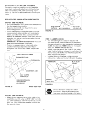
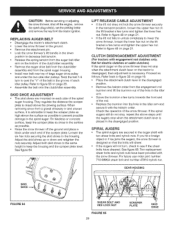
...hole in the down and retighten the nuts securely. REPLACING AUGER BELT • Disengage the tractor's attachment clutch. • Lower the snow thrower to the ground. • Remove the attachment pin • Lock the snow thrower's lift handle in the idler arm and secure it is raised above the surface as ... surface, it with the hairpin cotter Check the operation of the snow thrower If the spiral augers still do not stop, repeat the above steps until the augers stop when the attachment clutch lever on the tractor is disengaged, then adjustment is designed so that the bolts will shear...
...hole in the down and retighten the nuts securely. REPLACING AUGER BELT • Disengage the tractor's attachment clutch. • Lower the snow thrower to the ground. • Remove the attachment pin • Lock the snow thrower's lift handle in the idler arm and secure it is raised above the surface as ... surface, it with the hairpin cotter Check the operation of the snow thrower If the spiral augers still do not stop, repeat the above steps until the augers stop when the attachment clutch lever on the tractor is disengaged, then adjustment is designed so that the bolts will shear...
Operation Manual
Page 30
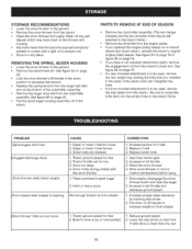
... the ground. * Remove the attachment ph_ See figure 54 on page 23. * Lock the snow thrower's lift handle in the down on lift handle to increase weight on front wheels Snow thrower rides up over snow 1 Tractor ground speed too fast 2 Bottom snow is icy or hard packed 1 Reduce ground speed 2 Lower the skid shoes so that...
... the ground. * Remove the attachment ph_ See figure 54 on page 23. * Lock the snow thrower's lift handle in the down on lift handle to increase weight on front wheels Snow thrower rides up over snow 1 Tractor ground speed too fast 2 Bottom snow is icy or hard packed 1 Reduce ground speed 2 Lower the skid shoes so that...


