Operation Manual
Page 1
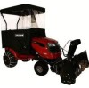
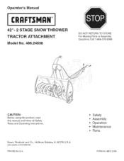
Operator's Manual CRQFTSNQ°N 42"= 2 STAGE SNOW THROWER TRACTOR ATTACHMENT Model No. 486.24838 DO NOT RETURN TO STORE For Missing Parts or Assembly Questions Call 1-866-576-8388 CAUTION: Before using this product, read this manual and follow all Safety Rules and Operating instructions. Safety Assembly Operation Maintenance Parts FORM NO. 49812 (2/06) Sears, Roebuck and Co., Hoffman Estates, IL 60179 U.S.A. www sears.corn/craftsman PRINTED iN U.S.A.
Operator's Manual CRQFTSNQ°N 42"= 2 STAGE SNOW THROWER TRACTOR ATTACHMENT Model No. 486.24838 DO NOT RETURN TO STORE For Missing Parts or Assembly Questions Call 1-866-576-8388 CAUTION: Before using this product, read this manual and follow all Safety Rules and Operating instructions. Safety Assembly Operation Maintenance Parts FORM NO. 49812 (2/06) Sears, Roebuck and Co., Hoffman Estates, IL 60179 U.S.A. www sears.corn/craftsman PRINTED iN U.S.A.
Operation Manual
Page 2
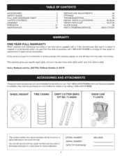
... record both the serial number and the date of purchase, call 1-800-4-MY-HOME® to the snow thrower. WHEEL WEIGHT TiRE CHAINS DRIFT CUTTER BARS KIT NO. 71-88294 SNOW CAB 71-24276 The model number and serial numbers will be purchased at most Craftsman outlets or by calling 1-800-4-MY-HOME®.
... record both the serial number and the date of purchase, call 1-800-4-MY-HOME® to the snow thrower. WHEEL WEIGHT TiRE CHAINS DRIFT CUTTER BARS KIT NO. 71-88294 SNOW CAB 71-24276 The model number and serial numbers will be purchased at most Craftsman outlets or by calling 1-800-4-MY-HOME®.
Operation Manual
Page 3
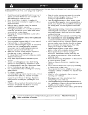
...the engine, remove the wire from the spark plug and then thor,3ughly inspect the snow thrower for damage Repair any damage before restarting and operating the snow thrower * If the snow thrower starts to vibrate abnormally, stop the engine and remove the key • When cleaning,...adults to the tractor. Do not overload the machine capacity by the manufacturer of all times. Exercisecautionat alltimes,whenusingpowerequipment. Keep the area of operation clear of the snow thrower (such as wheel weights, counter weights, cabs etc.) Never operate the snow thrower without proper instruction...
...the engine, remove the wire from the spark plug and then thor,3ughly inspect the snow thrower for damage Repair any damage before restarting and operating the snow thrower * If the snow thrower starts to vibrate abnormally, stop the engine and remove the key • When cleaning,...adults to the tractor. Do not overload the machine capacity by the manufacturer of all times. Exercisecautionat alltimes,whenusingpowerequipment. Keep the area of operation clear of the snow thrower (such as wheel weights, counter weights, cabs etc.) Never operate the snow thrower without proper instruction...
Operation Manual
Page 7
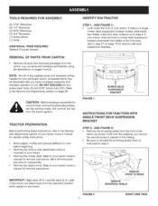
... 5/16" nylock nuts (CO) Refer to the Service and Adjustments section on page 29 CAUTION: Before starting to assemble the snow thrower, remove the spark plug wire(s), set the parking brake and remove the key from the tractor ignition TRACTOR PREPARATION Before performing these instructions, refer to the Service and Adjustments section of your...
... 5/16" nylock nuts (CO) Refer to the Service and Adjustments section on page 29 CAUTION: Before starting to assemble the snow thrower, remove the spark plug wire(s), set the parking brake and remove the key from the tractor ignition TRACTOR PREPARATION Before performing these instructions, refer to the Service and Adjustments section of your...
Operation Manual
Page 9
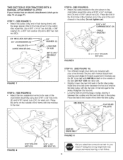
...frame with the notches 1othe rear STEP 10: (SEE FIGURE 10) • Two different length drive belts are included with your snow thrower Tractors with manual attachment clutches and single front deck suspension brackets use the 56" drive belt with the flat side o1 the belt ... FIGURE 8 5/16" NYLOCK NUT (CC) \ 5/16" x 3/4" HEX BOLT (E) (#48138) 7' DRIVE BELT FIGURE 10 Did you select the correct drive belt fo_ your tractor has an electric attachment clutch go to the inside of the c_utcWidler assembly using a 5/16" x 3/4" carriage bolt (O) and a 5/16" nylock nut (CC). STEP 7:...
...frame with the notches 1othe rear STEP 10: (SEE FIGURE 10) • Two different length drive belts are included with your snow thrower Tractors with manual attachment clutches and single front deck suspension brackets use the 56" drive belt with the flat side o1 the belt ... FIGURE 8 5/16" NYLOCK NUT (CC) \ 5/16" x 3/4" HEX BOLT (E) (#48138) 7' DRIVE BELT FIGURE 10 Did you select the correct drive belt fo_ your tractor has an electric attachment clutch go to the inside of the c_utcWidler assembly using a 5/16" x 3/4" carriage bolt (O) and a 5/16" nylock nut (CC). STEP 7:...
Operation Manual
Page 11
...CORRECT (Electric clutch tractors suspension bracket) DRIVE ... TTraYcPtoEr t DE3C8K", 4S2iZ" E ][ CLUTECleHctriTcYPE 56" BELT (PART #48138) T(LRTA) CLTaOwRn TTraYcPtoEr (GT) Garden Tractor TABLE 1 11 DECK48"SIZE l CLUTECleHctTriYcPE 48", 54" Electric SPRING ATTACH SPRING HERE 5TH LINK CHAIN (L.N. SIDE) 1...idler pulley to the upper idler arm. THIS SECTION IS FOR TRACTORS WITH AN ELECTRIC ATTACHMENT CLUTCH STEP 14: (SEE FIGURE 14)... each arm Place the arms on the outside of the frame with your tractor to avoid accidentally using it in the parts bag through the left front hole...
...CORRECT (Electric clutch tractors suspension bracket) DRIVE ... TTraYcPtoEr t DE3C8K", 4S2iZ" E ][ CLUTECleHctriTcYPE 56" BELT (PART #48138) T(LRTA) CLTaOwRn TTraYcPtoEr (GT) Garden Tractor TABLE 1 11 DECK48"SIZE l CLUTECleHctTriYcPE 48", 54" Electric SPRING ATTACH SPRING HERE 5TH LINK CHAIN (L.N. SIDE) 1...idler pulley to the upper idler arm. THIS SECTION IS FOR TRACTORS WITH AN ELECTRIC ATTACHMENT CLUTCH STEP 14: (SEE FIGURE 14)... each arm Place the arms on the outside of the frame with your tractor to avoid accidentally using it in the parts bag through the left front hole...
Operation Manual
Page 15
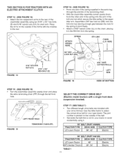
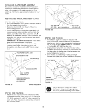
... Two different length drive belts are either rod operated (p 15), cable operated (p. 17) or electric (p. 19) Use the appropriate instructions for your snow thrower. DO NOT USE timeother belt • SlightEy _oosen the hex bolt next to the flat idler pulley Install the drive belt down ) position. &#...8226; Screw the trunnion (11)onto the end of the snow thrower engagement rod. • Locate the c_utcl_arm (where the mower clutch rod was connected) underneath the right hand side the tractor, iust to the inside of the clutch/idler assembly using two 5/16" x 3/4" hex...
... Two different length drive belts are either rod operated (p 15), cable operated (p. 17) or electric (p. 19) Use the appropriate instructions for your snow thrower. DO NOT USE timeother belt • SlightEy _oosen the hex bolt next to the flat idler pulley Install the drive belt down ) position. &#...8226; Screw the trunnion (11)onto the end of the snow thrower engagement rod. • Locate the c_utcl_arm (where the mower clutch rod was connected) underneath the right hand side the tractor, iust to the inside of the clutch/idler assembly using two 5/16" x 3/4" hex...

Operation Manual
Page 16
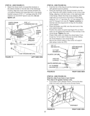
... arm slot Attach the trunnion (ll) to the slot using a rubber band tied to the engine pulley keeper * Attach the clutch/idler assembly to the tractor frame as shown when performing the next operation. ROD i / FIGURE 32 RIGHT SIDE VIEW STEP 83: (SEE FIGURE 33) • Make sure the ...is identical to the new one supplied• NEW ENGINE PULLEY KEEPER WITH ORIGINAL BOLT, NUT AND WASHER i ;; ...... The belt must be equipped with the snow thrower, reusing the original bolt, washer and nut. STEP32: (SEE FIGURE 82) * Be sure to lift up the front end of the engagement rod as ...
... arm slot Attach the trunnion (ll) to the slot using a rubber band tied to the engine pulley keeper * Attach the clutch/idler assembly to the tractor frame as shown when performing the next operation. ROD i / FIGURE 32 RIGHT SIDE VIEW STEP 83: (SEE FIGURE 33) • Make sure the ...is identical to the new one supplied• NEW ENGINE PULLEY KEEPER WITH ORIGINAL BOLT, NUT AND WASHER i ;; ...... The belt must be equipped with the snow thrower, reusing the original bolt, washer and nut. STEP32: (SEE FIGURE 82) * Be sure to lift up the front end of the engagement rod as ...
Operation Manual
Page 17
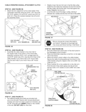
...in the bottom of the clutch/idler assembly using two 5/16" x 3/4" hex bolts (E), 5/16" washers (U) and 5/16" nylock nuts (CO) for your tractor has a 42" mower deck. Hook the end of the clutch spring over the pin and secure it with a 1/4" washer (T) and a 5/64" hair cotter pin (JJ).... i 1/4" WASHER (T) 5/16" NYLOCK NUT (CC) FIGURE 36 STEP 37: (SEE FIGURE 37) • Two different length drive belts are included with your snow thrower Tractors with manual attachment clutcl_es and dual front deck suspension brackets use the 55" drive belt with the flat side o1 the belt against the puEley...
...in the bottom of the clutch/idler assembly using two 5/16" x 3/4" hex bolts (E), 5/16" washers (U) and 5/16" nylock nuts (CO) for your tractor has a 42" mower deck. Hook the end of the clutch spring over the pin and secure it with a 1/4" washer (T) and a 5/64" hair cotter pin (JJ).... i 1/4" WASHER (T) 5/16" NYLOCK NUT (CC) FIGURE 36 STEP 37: (SEE FIGURE 37) • Two different length drive belts are included with your snow thrower Tractors with manual attachment clutcl_es and dual front deck suspension brackets use the 55" drive belt with the flat side o1 the belt against the puEley...

Operation Manual
Page 18
... already be placed to the inside of Tractor PULLEY / \\ FIGURE 89 / N FIGURE 40 VIEWED FROM UNDERNEATH 18 Hook the assembly's ...The belt must be equipped with a pulley keeper that secure the keeper Attach the new pulley keeper supplied with the snow thrower, reusing the original bolt, washer and nut. Lift the front of the assembly and attach it to the RH...on page 21. Attach the clutch/idler assembly to the tractor frame as follows. STEP 39: (SEE FIGURE 39) * Remove the engine pulley keeper from the side of the tractor frame by removing the washer and nut that is identical ...
... already be placed to the inside of Tractor PULLEY / \\ FIGURE 89 / N FIGURE 40 VIEWED FROM UNDERNEATH 18 Hook the assembly's ...The belt must be equipped with a pulley keeper that secure the keeper Attach the new pulley keeper supplied with the snow thrower, reusing the original bolt, washer and nut. Lift the front of the assembly and attach it to the RH...on page 21. Attach the clutch/idler assembly to the tractor frame as follows. STEP 39: (SEE FIGURE 39) * Remove the engine pulley keeper from the side of the tractor frame by removing the washer and nut that is identical ...
Operation Manual
Page 19
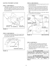
Attach a 3/32" hairpin cotter (LL) to the chain, placing it 55" CELT (PART #46989) TRACTOR TYPE DECK SiZE j_ CLUTCH TYPE (LT) Lawn Tractor 38", 42", 46" _ Electric 56" BELT (PART #48188) T(LRTA) CLTaOwnR TTraYcPtoEr TABLE 2 DEC4K8"SIZE _ CLUTECleHctriTcYPE 19 ELECTRIC ATTACHMENT CLUTCHES STEP 41: (... BOTTOM _- _ / LEFT FRONT HOLE FIGURE 42 TENSIONING CHAIN (PP) STEP 44: (SEE TABLE 2) Two different length drive belts are included with your snow thrower• Use the table below to select the correct drive belt for your type tractor The part number is printed on the outside ...
Attach a 3/32" hairpin cotter (LL) to the chain, placing it 55" CELT (PART #46989) TRACTOR TYPE DECK SiZE j_ CLUTCH TYPE (LT) Lawn Tractor 38", 42", 46" _ Electric 56" BELT (PART #48188) T(LRTA) CLTaOwnR TTraYcPtoEr TABLE 2 DEC4K8"SIZE _ CLUTECleHctriTcYPE 19 ELECTRIC ATTACHMENT CLUTCHES STEP 41: (... BOTTOM _- _ / LEFT FRONT HOLE FIGURE 42 TENSIONING CHAIN (PP) STEP 44: (SEE TABLE 2) Two different length drive belts are included with your snow thrower• Use the table below to select the correct drive belt for your type tractor The part number is printed on the outside ...

Operation Manual
Page 21
...; bolts (D) and 5/16" Ny[ock nuts (CO). LIFT HANDLE \, STEP 50: (SEE FIGURE 49) • Tilt the snow thrower back down into the locked position. Refer also to the Service and Adjustments section on the right side of the cable wire into the... _, [_ 5/16" _ 1-3/4 _ CARRIAGE B,,OL_ BOWEDWASHER{Y) _ I \ _ WASBER ]/ i HERXDT 5/16" NYLOCK NUT f,CC) / /\ CABLE FIGURE 50 .... _; Insert the end of the snow thrower. CONTROL ASSTEILMTBLY "_ LEFT SIDEVIEW FIGURE 48 RIGHT SIDE VIEW 21 Fasten the handle to eliminate slack in this manual. ASSEMBLY OFTHE SNOWTHROWER STEP 48: (SEE...
...; bolts (D) and 5/16" Ny[ock nuts (CO). LIFT HANDLE \, STEP 50: (SEE FIGURE 49) • Tilt the snow thrower back down into the locked position. Refer also to the Service and Adjustments section on the right side of the cable wire into the... _, [_ 5/16" _ 1-3/4 _ CARRIAGE B,,OL_ BOWEDWASHER{Y) _ I \ _ WASBER ]/ i HERXDT 5/16" NYLOCK NUT f,CC) / /\ CABLE FIGURE 50 .... _; Insert the end of the snow thrower. CONTROL ASSTEILMTBLY "_ LEFT SIDEVIEW FIGURE 48 RIGHT SIDE VIEW 21 Fasten the handle to eliminate slack in this manual. ASSEMBLY OFTHE SNOWTHROWER STEP 48: (SEE...
Operation Manual
Page 22
... (HH) _! I/4"FLANGED LOCK NUT (Z) /_. \\\ _\ FIGURE 52 RIGHT SiDE ViEW STEP 54: (SEE FIGURE 53) Skip this step if you have a lawn tractor. STEP 52: (SEE FIGURE 51) • Attach the chute crank rod assembly brackets to the plastic bracket on the right hand side of the flange... BRACKET CHUTE CRANK -- If not, loosen by 1/4 turn each side o1 the snow thrower frame• FIGURE 53 22 STOP BOLT RIGHT SIDE ViEW This step is for garden tractors only. • If you have a (GT) Garden Tractor, remove timestop bolts from each of the notches in the chute flange Tighten the...
... (HH) _! I/4"FLANGED LOCK NUT (Z) /_. \\\ _\ FIGURE 52 RIGHT SiDE ViEW STEP 54: (SEE FIGURE 53) Skip this step if you have a lawn tractor. STEP 52: (SEE FIGURE 51) • Attach the chute crank rod assembly brackets to the plastic bracket on the right hand side of the flange... BRACKET CHUTE CRANK -- If not, loosen by 1/4 turn each side o1 the snow thrower frame• FIGURE 53 22 STOP BOLT RIGHT SIDE ViEW This step is for garden tractors only. • If you have a (GT) Garden Tractor, remove timestop bolts from each of the notches in the chute flange Tighten the...

Operation Manual
Page 23
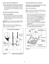
.... The "V" side of the belt must be seated in the tractor's side plates. ATTACHING SNOW THROWER TO TRACTOR NOTE: An additional person's help may be rolled forward to attach the snow thrower. * Remove the Attachment Pin from the snow thrower. * Extend the auger belt out behind the snow thrower, centering it between the two pulleys on a flat_ level surface so...
.... The "V" side of the belt must be seated in the tractor's side plates. ATTACHING SNOW THROWER TO TRACTOR NOTE: An additional person's help may be rolled forward to attach the snow thrower. * Remove the Attachment Pin from the snow thrower. * Extend the auger belt out behind the snow thrower, centering it between the two pulleys on a flat_ level surface so...
Operation Manual
Page 24
...CLUTCH/IDLER ASSEMBLY ATTACHING WEIGHT TRAY TO TRACTOR ATTACHING TO (LT) LAWN TRACTORS WITH A SINGLE FRONT DECK SUSPENSION BRACKET STEP 60: (SEE FIGURE 88) NOTE: Go to step 63 on top of the tractor hitch and fasten the side braces to the rear hole in each side of the tractor's draw bar Assemble the slotted end...the chain though the pivot lock pin. INSTALLING THE ATTACHMENT PIN STEP 88: (REFER SACKTO FIGURE 54 ON PAGE 23) * Lift the front of the snow blower to align the holes in the side of the C{utch/Idbr assembly install the 1/8" hairpin cotter (KK) through the holes. To prevent the ...
...CLUTCH/IDLER ASSEMBLY ATTACHING WEIGHT TRAY TO TRACTOR ATTACHING TO (LT) LAWN TRACTORS WITH A SINGLE FRONT DECK SUSPENSION BRACKET STEP 60: (SEE FIGURE 88) NOTE: Go to step 63 on top of the tractor hitch and fasten the side braces to the rear hole in each side of the tractor's draw bar Assemble the slotted end...the chain though the pivot lock pin. INSTALLING THE ATTACHMENT PIN STEP 88: (REFER SACKTO FIGURE 54 ON PAGE 23) * Lift the front of the snow blower to align the holes in the side of the C{utch/Idbr assembly install the 1/8" hairpin cotter (KK) through the holes. To prevent the ...
Operation Manual
Page 26
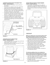
... ALTERNATE INSTRUCTIONS FOR WEIGRTTRAY STEP 83: (SEE FIGURE 61) Block up the rea_ of the tractor to allow . \ FIGURE 63 REAR REFLECTORS (QQ) CHECKLIST Before you operate your snow thrower, please review the following checklist to help ensure that the _ift handle will lock into and release ...operation of tilt control for upper chute • Verify that you will obtain the best performance from your snow thrower. ATTACH REFLECTORS TO REAR FENDER STEP 68: (SEE FIGURE 63) • If your tractor is unthreaded, screw a 3/8" x 3/4" self threading bolt (H) into and out of the hole to create...
... ALTERNATE INSTRUCTIONS FOR WEIGRTTRAY STEP 83: (SEE FIGURE 61) Block up the rea_ of the tractor to allow . \ FIGURE 63 REAR REFLECTORS (QQ) CHECKLIST Before you operate your snow thrower, please review the following checklist to help ensure that the _ift handle will lock into and release ...operation of tilt control for upper chute • Verify that you will obtain the best performance from your snow thrower. ATTACH REFLECTORS TO REAR FENDER STEP 68: (SEE FIGURE 63) • If your tractor is unthreaded, screw a 3/8" x 3/4" self threading bolt (H) into and out of the hole to create...
Operation Manual
Page 27
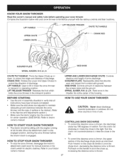
...BEFORE STARTING * Use the end of surface to be sitting with the various controls and their locations. KNOW YOUR SNOW THROWER Read this owner's manual and safety rules before the tractor clutch is thrown 27 LIFT RELEASE TRIGGER CHUTE TILT HANDLE 3RANK ROD f SCRAPER PLATE /j SPIRAL AUGERS, R.H.& ...fan at full throttle Move the attachment dutch to verify that absorbs wear and impact from contact with your tractor owner's manual HOW TO USE YOUR SNOW THROWER CAUTION: Never direct discharge towards bystanders or windows Do not allow anyone in the transport position UPPER AND LOWER...
...BEFORE STARTING * Use the end of surface to be sitting with the various controls and their locations. KNOW YOUR SNOW THROWER Read this owner's manual and safety rules before the tractor clutch is thrown 27 LIFT RELEASE TRIGGER CHUTE TILT HANDLE 3RANK ROD f SCRAPER PLATE /j SPIRAL AUGERS, R.H.& ...fan at full throttle Move the attachment dutch to verify that absorbs wear and impact from contact with your tractor owner's manual HOW TO USE YOUR SNOW THROWER CAUTION: Never direct discharge towards bystanders or windows Do not allow anyone in the transport position UPPER AND LOWER...
Operation Manual
Page 28
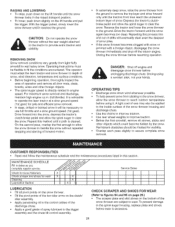
...FOR WEAR (Refer to figures 64 and 65 on page 29.) • The scraper plate and skid shoes on the bottom of the snow thrower are subject to the snow thrower, allow thesnowthrowetro handlethesnowwithoutrepeated stoppingandstartingofforwardmotion. • Inextremeldyeepsnowr,aisethesnowthrowefrrom thegroundto removethetoplayeranddriveforward onlyuntilthetractorsfronttiresreachtheuncleared bottomlayerof snowD. Driveforwardintothesnowd, epressthetractor's clutch-brakpeedalandallowthespiralaugerto clear thesnowRepeathismethoduntila pathiscleared. DANGER: Shutoffengineand disengagesnowthrowebr...
...FOR WEAR (Refer to figures 64 and 65 on page 29.) • The scraper plate and skid shoes on the bottom of the snow thrower are subject to the snow thrower, allow thesnowthrowetro handlethesnowwithoutrepeated stoppingandstartingofforwardmotion. • Inextremeldyeepsnowr,aisethesnowthrowefrrom thegroundto removethetoplayeranddriveforward onlyuntilthetractorsfronttiresreachtheuncleared bottomlayerof snowD. Driveforwardintothesnowd, epressthetractor's clutch-brakpeedalandallowthespiralaugerto clear thesnowRepeathismethoduntila pathiscleared. DANGER: Shutoffengineand disengagesnowthrowebr...
Operation Manual
Page 29
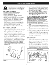
... are mounted on page 21 CLUTCH DISENGAGEMENT ADJUSTMENT (For tractors with the snow thrower. They regulate the distance the scraper plate is necessary. REPLACING AUGER BELT • Disengage the tractor's attachment clutch. • Lower the snow thrower to the ground. • Remove the attachment pin • Lock the snow thrower's lift handle in the down and retighten the...
... are mounted on page 21 CLUTCH DISENGAGEMENT ADJUSTMENT (For tractors with the snow thrower. They regulate the distance the scraper plate is necessary. REPLACING AUGER BELT • Disengage the tractor's attachment clutch. • Lower the snow thrower to the ground. • Remove the attachment pin • Lock the snow thrower's lift handle in the down and retighten the...
Operation Manual
Page 30
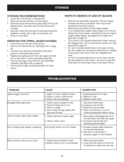
... wheels slide instead of steering Not enough traction at front wheels CORRI=CTION 1. Replace V belt 3. STORAGE RECOMMENDATIONS * Lower the snow thrower to the ground. * Remove the snow thrower from the tractor. * Clean the snow thrower thoroughly Wash off any salt deposit which may be used , remove the rear weight tray, leaving the bolts that front of skid...
... wheels slide instead of steering Not enough traction at front wheels CORRI=CTION 1. Replace V belt 3. STORAGE RECOMMENDATIONS * Lower the snow thrower to the ground. * Remove the snow thrower from the tractor. * Clean the snow thrower thoroughly Wash off any salt deposit which may be used , remove the rear weight tray, leaving the bolts that front of skid...


