Operation Manual
Page 1
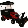
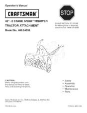
www sears.corn/craftsman PRINTED iN U.S.A. Sears, Roebuck and Co., Hoffman Estates, IL 60179 U.S.A. Operator's Manual CRQFTSNQ°N 42"= 2 STAGE SNOW THROWER TRACTOR ATTACHMENT Model No. 486.24838 DO NOT RETURN TO STORE For Missing Parts or Assembly Questions Call 1-866-576-8388 CAUTION: Before using this product, read this manual and follow all Safety Rules and Operating instructions. Safety Assembly Operation Maintenance Parts FORM NO. 49812 (2/06)
www sears.corn/craftsman PRINTED iN U.S.A. Sears, Roebuck and Co., Hoffman Estates, IL 60179 U.S.A. Operator's Manual CRQFTSNQ°N 42"= 2 STAGE SNOW THROWER TRACTOR ATTACHMENT Model No. 486.24838 DO NOT RETURN TO STORE For Missing Parts or Assembly Questions Call 1-866-576-8388 CAUTION: Before using this product, read this manual and follow all Safety Rules and Operating instructions. Safety Assembly Operation Maintenance Parts FORM NO. 49812 (2/06)
Operation Manual
Page 2
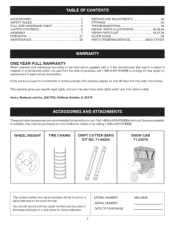
...,38 REPAIR PARTS LIST 35,37,38 SLOPE GUIDE 39 PARTS ORDERING/SERVICE BACK COVER ONE YEAR FULL WARRANTY When operated and maintained according to the instructions supplied with your unit Call 1-8O0-4-MY-HOME® to find out if they may also have other accessories are available. WHEEL WEIGHT TiRE CHAINS DRIFT CUTTER BARS KIT NO. 71-88294 SNOW CAB 71-24276 The model number and serial numbers...
...,38 REPAIR PARTS LIST 35,37,38 SLOPE GUIDE 39 PARTS ORDERING/SERVICE BACK COVER ONE YEAR FULL WARRANTY When operated and maintained according to the instructions supplied with your unit Call 1-8O0-4-MY-HOME® to find out if they may also have other accessories are available. WHEEL WEIGHT TiRE CHAINS DRIFT CUTTER BARS KIT NO. 71-88294 SNOW CAB 71-24276 The model number and serial numbers...
Operation Manual
Page 3
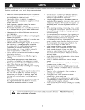
... used and remove all door mats, sleds, boards, wires and other safety protection devices in or out of trouble. • Stop the engine whenever you leave the operating position, before starting the engine Do not remove the fuel cap or fill the fuel tank while the engine is adjusted to clear steep slopes. Exercisecautionat alltimes,whenusingpowerequipment. Disengage the attachment clutch lever or switch, lower the snow thrower, shift into material at high transport speed...
... used and remove all door mats, sleds, boards, wires and other safety protection devices in or out of trouble. • Stop the engine whenever you leave the operating position, before starting the engine Do not remove the fuel cap or fill the fuel tank while the engine is adjusted to clear steep slopes. Exercisecautionat alltimes,whenusingpowerequipment. Disengage the attachment clutch lever or switch, lower the snow thrower, shift into material at high transport speed...
Operation Manual
Page 7
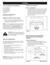
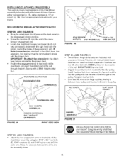
... from the operators position while seated on the t{actor. Refer to step 2. If there is a single mower deck suspension bracket located underneath the middle of the front axle, continue on page 29 CAUTION: Before starting to assemble the snow thrower, remove the spark plug wire(s), set the parking brake and remove the key from falling Be sure to your tractor owner's manual for removal instructions Mark all of the supplied parts and...
... from the operators position while seated on the t{actor. Refer to step 2. If there is a single mower deck suspension bracket located underneath the middle of the front axle, continue on page 29 CAUTION: Before starting to assemble the snow thrower, remove the spark plug wire(s), set the parking brake and remove the key from falling Be sure to your tractor owner's manual for removal instructions Mark all of the supplied parts and...
Operation Manual
Page 9
... drive belt fo_ your tractor has an electric attachment clutch go to the inside of the other belt. • Slightly loosen the hex bolt next to the flat idler pulley Install the drive belt down ) and the large spacer (SS) to the hole shown in the dutch/ idler assembly Use a 3/8" x 3-1/4" hex bolt (B), a 3/8" washer (X), a 3/8" lock washer (S) and a 3/8" hex lock nut (DD). 3/8" BEX LOCK NUT (DD) _ 3/8" LOCKWASHER (S) _-_ _; 3/8" _'== WASHER (X) STEP 9: (SEE FIGURE 9) Attach the cable...
... drive belt fo_ your tractor has an electric attachment clutch go to the inside of the other belt. • Slightly loosen the hex bolt next to the flat idler pulley Install the drive belt down ) and the large spacer (SS) to the hole shown in the dutch/ idler assembly Use a 3/8" x 3-1/4" hex bolt (B), a 3/8" washer (X), a 3/8" lock washer (S) and a 3/8" hex lock nut (DD). 3/8" BEX LOCK NUT (DD) _ 3/8" LOCKWASHER (S) _-_ _; 3/8" _'== WASHER (X) STEP 9: (SEE FIGURE 9) Attach the cable...
Operation Manual
Page 10
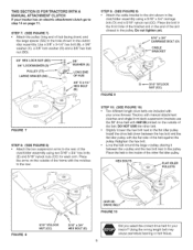
... 13) • Assemble the drive belt onto the engine pulley first and then onto the large pulley on page 21. IMPORTANT: Do Not assemble the "V" belt outside of the engine pulley keepers or outside of Tractor BOLT FIGURE 18 10 VIEWED FROM UNDERNEATH Lift the front of the clutch cable spring over the pin and secure it . PULLEY Le# Side of the tractor frame. PIVOT LOCK PIN (MM) use this hole...
... 13) • Assemble the drive belt onto the engine pulley first and then onto the large pulley on page 21. IMPORTANT: Do Not assemble the "V" belt outside of the engine pulley keepers or outside of Tractor BOLT FIGURE 18 10 VIEWED FROM UNDERNEATH Lift the front of the clutch cable spring over the pin and secure it . PULLEY Le# Side of the tractor frame. PIVOT LOCK PIN (MM) use this hole...
Operation Manual
Page 11
...) onto the bolt and nut, leaving enough gap between the nuts for each arm Place the arms on the outside of the belt Set aside the belt that is printed on the outside of the frame with your tractor to the upper idler arm. Use the table below to select the correct drive belt for your type tractor The part number is not for your snow thrower.
...) onto the bolt and nut, leaving enough gap between the nuts for each arm Place the arms on the outside of the belt Set aside the belt that is printed on the outside of the frame with your tractor to the upper idler arm. Use the table below to select the correct drive belt for your type tractor The part number is not for your snow thrower.
Operation Manual
Page 15
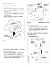
... the large v-pulley, placing it between the v-pulley and the hex bolt next to tractors with your snow thrower. ROD OPERATED MANUAL ATTACHMENT CLUTCH STEP 29: (SEE FIGURE 29) • Move the attachment dutch lever on the outside of the Clutch/Idler assembly to the pulley HEX BOLTS \ \ \ \ FLAT IDLER PULLEY (#46989) DRIVE BELT FIGURE 31 Did you choose the correct drive belt for your tractor? INSTALLING CLUTCH/IDLER ASSEMBLY This section covers the installation of the...
... the large v-pulley, placing it between the v-pulley and the hex bolt next to tractors with your snow thrower. ROD OPERATED MANUAL ATTACHMENT CLUTCH STEP 29: (SEE FIGURE 29) • Move the attachment dutch lever on the outside of the Clutch/Idler assembly to the pulley HEX BOLTS \ \ \ \ FLAT IDLER PULLEY (#46989) DRIVE BELT FIGURE 31 Did you choose the correct drive belt for your tractor? INSTALLING CLUTCH/IDLER ASSEMBLY This section covers the installation of the...

Operation Manual
Page 16
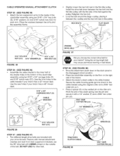
i_ C TRUNNION (11) ! The belt must be equipped with the snow thrower, reusing the original bolt, washer and nut. You can temporarily support the rod using a rubber band tied to the engine pulley keeper * Attach the clutch/idler assembly to the tractor frame as shown when performing the next operation. NOTE: Some tractors may already be placed to the inside of the tractor frame• Lift the...
i_ C TRUNNION (11) ! The belt must be equipped with the snow thrower, reusing the original bolt, washer and nut. You can temporarily support the rod using a rubber band tied to the engine pulley keeper * Attach the clutch/idler assembly to the tractor frame as shown when performing the next operation. NOTE: Some tractors may already be placed to the inside of the tractor frame• Lift the...
Operation Manual
Page 17
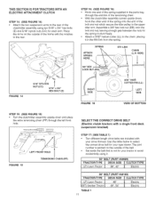
... length drive belts are included with your snow thrower Tractors with manual attachment clutcl_es and dual front deck suspension brackets use the 55" drive belt with #46989 pdnted on the idler arm. Hook the end of the clutch spring over the pin and secure it between the arms and the assembly frame. , Slightly loosen the hex bolt next to the flat idler pulley Install the drive belt down ) to the cable bracket using...
... length drive belts are included with your snow thrower Tractors with manual attachment clutcl_es and dual front deck suspension brackets use the 55" drive belt with #46989 pdnted on the idler arm. Hook the end of the clutch spring over the pin and secure it between the arms and the assembly frame. , Slightly loosen the hex bolt next to the flat idler pulley Install the drive belt down ) to the cable bracket using...

Operation Manual
Page 18
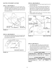
... snow thrower, reusing the original bolt, washer and nut. Attach the clutch/idler assembly to the RH and L.H hanger brackets using two pivot lock pins (MM) and 1/8" hairpin cotters (KK) NEW ENGINE PULLEY KEEPER WITH ORIGINAL BOLT, NUT AND WASHER PIVOT LOCK PIN (MM) (use second hole) \ 1/8" HAIRPIN COTTER STEP 40: (SEE FIGURE 40) Assemble the short "V" belt onto the engine pulley and then onto the large pulley on page 21. NOTE: Some tractors...
... snow thrower, reusing the original bolt, washer and nut. Attach the clutch/idler assembly to the RH and L.H hanger brackets using two pivot lock pins (MM) and 1/8" hairpin cotters (KK) NEW ENGINE PULLEY KEEPER WITH ORIGINAL BOLT, NUT AND WASHER PIVOT LOCK PIN (MM) (use second hole) \ 1/8" HAIRPIN COTTER STEP 40: (SEE FIGURE 40) Assemble the short "V" belt onto the engine pulley and then onto the large pulley on page 21. NOTE: Some tractors...
Operation Manual
Page 19
... bolt head and assemble a 3/8" hex lock nut (DD) onto the bolt, leaving enough space for the spring to the chain, placing it 55" CELT (PART #46989) TRACTOR TYPE DECK SiZE j_ CLUTCH TYPE (LT) Lawn Tractor 38", 42", 46" _ Electric 56" BELT (PART #48188) T(LRTA) CLTaOwnR TTraYcPtoEr TABLE 2 DEC4K8"SIZE _ CLUTECleHctriTcYPE 19 Attach a 3/32" hairpin cotter (LL) to pivot freely between the arms and the assembly frame STEP 43: (SEE FIGURE 43) Hook the spring...
... bolt head and assemble a 3/8" hex lock nut (DD) onto the bolt, leaving enough space for the spring to the chain, placing it 55" CELT (PART #46989) TRACTOR TYPE DECK SiZE j_ CLUTCH TYPE (LT) Lawn Tractor 38", 42", 46" _ Electric 56" BELT (PART #48188) T(LRTA) CLTaOwnR TTraYcPtoEr TABLE 2 DEC4K8"SIZE _ CLUTECleHctriTcYPE 19 Attach a 3/32" hairpin cotter (LL) to pivot freely between the arms and the assembly frame STEP 43: (SEE FIGURE 43) Hook the spring...

Operation Manual
Page 21
... cable wire. HINT: For easier assembly of the lift release cable, tilt the snow thrower forward onto the spiral auger •• CRANK ROD 5t16" NYLOCK NUT (CC) .SUPPORT TUBE FIGURE 49 LEFT SIDE ViEW STEP 51: (SEE FIGURE 50) * Attach the chute tilt control assembly to the Service and Adjustments section on the left side of the discharge housing using two 5/16" x 1-1/4" carriage bolts (M), and 5/16" Nylock nuts...
... cable wire. HINT: For easier assembly of the lift release cable, tilt the snow thrower forward onto the spiral auger •• CRANK ROD 5t16" NYLOCK NUT (CC) .SUPPORT TUBE FIGURE 49 LEFT SIDE ViEW STEP 51: (SEE FIGURE 50) * Attach the chute tilt control assembly to the Service and Adjustments section on the left side of the discharge housing using two 5/16" x 1-1/4" carriage bolts (M), and 5/16" Nylock nuts...

Operation Manual
Page 23
... forward to increase slack in the belt (attachment pin must mate with the shoulder bolts in the tractor's side plates. TWIST 1/4 TURN :i AUGER PULLEY _ i TWIST 1/4 TURN IDLER PULLEY IDLER PULLEY FIGURE 88 INSTALLING THE AUGER BELT STEP 57: (SEE FIGURE 86) * Push the lift handle down to attach the snow thrower. * Remove the Attachment Pin from the snow thrower. * Extend the auger belt out behind the snow thrower, making sure the belt is still fooped over the top...
... forward to increase slack in the belt (attachment pin must mate with the shoulder bolts in the tractor's side plates. TWIST 1/4 TURN :i AUGER PULLEY _ i TWIST 1/4 TURN IDLER PULLEY IDLER PULLEY FIGURE 88 INSTALLING THE AUGER BELT STEP 57: (SEE FIGURE 86) * Push the lift handle down to attach the snow thrower. * Remove the Attachment Pin from the snow thrower. * Extend the auger belt out behind the snow thrower, making sure the belt is still fooped over the top...
Operation Manual
Page 26
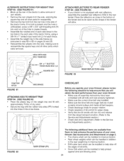
... operate your snow thrower, please review the following checklist to help ensure that the _ift handle will obtain the best performance from the axle, retaining the square key and all belt keepers • Check discharge chute for proper rotation • Check operation of tilt control for each side of the tractor frame, using a 3/8-18 x 1" slotted truss head bolt (J) for upper chute • Verify that you will lock...
... operate your snow thrower, please review the following checklist to help ensure that the _ift handle will obtain the best performance from the axle, retaining the square key and all belt keepers • Check discharge chute for proper rotation • Check operation of tilt control for each side of the tractor frame, using a 3/8-18 x 1" slotted truss head bolt (J) for upper chute • Verify that you will lock...
Operation Manual
Page 27
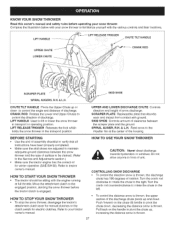
... operating position. SCRAPER PLATE Replaceable plate that all instructions have been properly completed. Pull back on the chute tilt handle to the left. LiFT HANDLE Used to lift or lower the snow thrower to familiarize yourself with ground SKID SHOE Controls amount of clearance between the snow thrower and the type of assembly checklist to the Service and Adjustments section ) * Make sure the tractor engine has the correct oil for electdc clutches...
... operating position. SCRAPER PLATE Replaceable plate that all instructions have been properly completed. Pull back on the chute tilt handle to the left. LiFT HANDLE Used to lift or lower the snow thrower to familiarize yourself with ground SKID SHOE Controls amount of clearance between the snow thrower and the type of assembly checklist to the Service and Adjustments section ) * Make sure the tractor engine has the correct oil for electdc clutches...
Operation Manual
Page 28
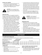
... the spiral auger housing, replace plate and shoes before using it II It LUBRICATION • Oil aH pivot points on the snow thrower. • Oil the pivot points of the two idler arms on the clutcW idler assembly • Apply penetrating oil to the control cables of the discharge chute • Apply a good grade of spray lubricant to the trigger assembly and the chute tilt control assembly CHECK SCRAPER...
... the spiral auger housing, replace plate and shoes before using it II It LUBRICATION • Oil aH pivot points on the snow thrower. • Oil the pivot points of the two idler arms on the clutcW idler assembly • Apply penetrating oil to the control cables of the discharge chute • Apply a good grade of spray lubricant to the trigger assembly and the chute tilt control assembly CHECK SCRAPER...
Operation Manual
Page 29
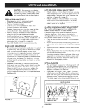
... the clutchddler assembly. • Remove the auger drive belt from the clutch/idler assembly and from the engagement rod trunnion and lift the trunnion out of the snow thrower If the spiral augers still do not stop when the attachment clutch lever on page 21 CLUTCH DISENGAGEMENT ADJUSTMENT (For tractors with the hairpin cotter Check the operation of the hole in the idler arm Screw the trunnion a few turns and...
... the clutchddler assembly. • Remove the auger drive belt from the clutch/idler assembly and from the engagement rod trunnion and lift the trunnion out of the snow thrower If the spiral augers still do not stop when the attachment clutch lever on page 21 CLUTCH DISENGAGEMENT ADJUSTMENT (For tractors with the hairpin cotter Check the operation of the hole in the idler arm Screw the trunnion a few turns and...
Operation Manual
Page 30
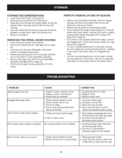
... auger housing assembly off of the tractor PARTS TO REMOVE AT END OF SEASON Remove the clutch/idler assembly (The two hanger brackets and the two shoulder bolts may be left attached to the tractor frame) • Remove the drive belt from the engine pulley. Replace V belt 3. increase to full throttle 3. Allow snow thrower to cool to outdoor temperature before using 1 Stop engine, disengage the snow thrower clutch and clear the auger 2 Increase to full throttle and decrease ground speed...
... auger housing assembly off of the tractor PARTS TO REMOVE AT END OF SEASON Remove the clutch/idler assembly (The two hanger brackets and the two shoulder bolts may be left attached to the tractor frame) • Remove the drive belt from the engine pulley. Replace V belt 3. increase to full throttle 3. Allow snow thrower to cool to outdoor temperature before using 1 Stop engine, disengage the snow thrower clutch and clear the auger 2 Increase to full throttle and decrease ground speed...
Operation Manual
Page 35
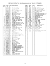
...73 47572 49812 QTY. DESCRIPTION 2 Pin, Pivot Lock 2 Pin, Hair Cotter #4 (1/8") 4 Carriage Bolt, 3/8-16 x 1" 1 Bracket, Chute Anti-rotation 3 Lock Washer, 3/8" 1 Plastic Cap 1 Hanger Bracket Assembly, RH 1 Hanger Bracket Assembly, L.H. 1 Keeper, Engine Pufley 4 Bolt, Shoulder 2 Bracket, Do_,m Stop 1 Washer, 6 Hex Lock Nut, 1/4" Flanged 1 Chute, Upper 1 Guide, Cable 2 Pulley, V Type 4" 1 Pulley, V Type 1 Hex Bolt, 5/16-18 x 1-1/2" 1 Screw, 1/4-14x8/8" 3 Chute Keeper 6 Hex Bolt, 1/4-20 x 1" 1 Chute, Lower 2 Washer, 3/8" 6 Hex Lock Nut, 3/8-16 Flanged 1 Owner's Manual 35 Wrt 31 47615 32 741...
...73 47572 49812 QTY. DESCRIPTION 2 Pin, Pivot Lock 2 Pin, Hair Cotter #4 (1/8") 4 Carriage Bolt, 3/8-16 x 1" 1 Bracket, Chute Anti-rotation 3 Lock Washer, 3/8" 1 Plastic Cap 1 Hanger Bracket Assembly, RH 1 Hanger Bracket Assembly, L.H. 1 Keeper, Engine Pufley 4 Bolt, Shoulder 2 Bracket, Do_,m Stop 1 Washer, 6 Hex Lock Nut, 1/4" Flanged 1 Chute, Upper 1 Guide, Cable 2 Pulley, V Type 4" 1 Pulley, V Type 1 Hex Bolt, 5/16-18 x 1-1/2" 1 Screw, 1/4-14x8/8" 3 Chute Keeper 6 Hex Bolt, 1/4-20 x 1" 1 Chute, Lower 2 Washer, 3/8" 6 Hex Lock Nut, 3/8-16 Flanged 1 Owner's Manual 35 Wrt 31 47615 32 741...


