Hardware Reference Guide - dx2400 MT
Page 5
Table of contents 1 Product Features Standard Configuration Features ...1 Front Panel Components ...2 Media Card Reader Components ...3 Rear Panel Components ...4 Keyboard ...5 Using the Windows Logo Key 6 Serial Number Location ...7 2 Hardware Upgrades Warnings and Cautions ...8 Removing the Computer Access Panel 9 Replacing the Computer Access Panel 10 Removing the Front Bezel ...11 Removing Bezel Blanks ...12 Replacing the Front Bezel...
Table of contents 1 Product Features Standard Configuration Features ...1 Front Panel Components ...2 Media Card Reader Components ...3 Rear Panel Components ...4 Keyboard ...5 Using the Windows Logo Key 6 Serial Number Location ...7 2 Hardware Upgrades Warnings and Cautions ...8 Removing the Computer Access Panel 9 Replacing the Computer Access Panel 10 Removing the Front Bezel ...11 Removing Bezel Blanks ...12 Replacing the Front Bezel...
Hardware Reference Guide - dx2400 MT
Page 10
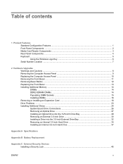
... Computer Setup (F10) Utility Guide. 4 Chapter 1 Product Features ENWW The monitor connector on the card and the system board may vary by model. Rear Panel Components Figure 1-4 Rear Panel Components Table 1-3 Rear Panel Components 1 Power Cord Connector 2 Voltage Select Switch 6 Line-Out Connector for powered audio devices (green) 7 Microphone Connector 3 Line-In Audio Connector (blue) 8 Universal...
... Computer Setup (F10) Utility Guide. 4 Chapter 1 Product Features ENWW The monitor connector on the card and the system board may vary by model. Rear Panel Components Figure 1-4 Rear Panel Components Table 1-3 Rear Panel Components 1 Power Cord Connector 2 Voltage Select Switch 6 Line-Out Connector for powered audio devices (green) 7 Microphone Connector 3 Line-In Audio Connector (blue) 8 Universal...

Hardware Reference Guide - dx2400 MT
Page 25
Before installing an expansion card, remove the expansion slot cover or the existing expansion card. 5. Remove the screw from the slot cover lock then slide the slot cover lock up to remove it from the chassis. ENWW Removing or Installing an Expansion Card 19 Remove the computer access panel. 6. Figure 2-9 Opening the Slot Cover Lock 8. On the rear of the computer chassis. 7. Locate the correct vacant expansion socket on the system board and the corresponding expansion slot on the back of the computer, a slot cover lock secures the expansion card brackets in place.
Before installing an expansion card, remove the expansion slot cover or the existing expansion card. 5. Remove the screw from the slot cover lock then slide the slot cover lock up to remove it from the chassis. ENWW Removing or Installing an Expansion Card 19 Remove the computer access panel. 6. Figure 2-9 Opening the Slot Cover Lock 8. On the rear of the computer chassis. 7. Locate the correct vacant expansion socket on the system board and the corresponding expansion slot on the back of the computer, a slot cover lock secures the expansion card brackets in place.

Hardware Reference Guide - dx2400 MT
Page 26
... installing. Be sure to remove the appropriate shield for the expansion card you must use a flatblade screwdriver to pry out the metal shield on the rear panel that may be attached to scrape the card against the other components. a. If you are installing an expansion card in a vacant socket, you are removing...
... installing. Be sure to remove the appropriate shield for the expansion card you must use a flatblade screwdriver to pry out the metal shield on the rear panel that may be attached to scrape the card against the other components. a. If you are installing an expansion card in a vacant socket, you are removing...

Hardware Reference Guide - dx2400 MT
Page 28
Connect internal cables to the installed card, if needed . 14. Replace the computer access panel. 22 Chapter 2 Hardware Upgrades ENWW Figure 2-13 Installing an Expansion Card NOTE: When installing an expansion card, press firmly on the chassis. To install a new ...expansion card, hold the card just above the expansion socket on the system board then move the card toward the rear of the chassis so that the bottom of the bracket on the card slides into the expansion socket on the system board. Figure 2-14 Securing...
Connect internal cables to the installed card, if needed . 14. Replace the computer access panel. 22 Chapter 2 Hardware Upgrades ENWW Figure 2-13 Installing an Expansion Card NOTE: When installing an expansion card, press firmly on the chassis. To install a new ...expansion card, hold the card just above the expansion socket on the system board then move the card toward the rear of the chassis so that the bottom of the bracket on the card slides into the expansion socket on the system board. Figure 2-14 Securing...

Hardware Reference Guide - dx2400 MT
Page 33
...all removable media, such as the system is always present on state, voltage is plugged into an active AC outlet. Remove the access panel and front bezel. 6. You must disconnect the power cord to avoid damage to the internal components of the optical drive. Remove/disengage ...any external devices. 4. Disconnect the power cord from the rear of the computer. 5. Disconnect the power cable (1) and data cable (2) from the power outlet and disconnect any external devices. Removing an Optical...
...all removable media, such as the system is always present on state, voltage is plugged into an active AC outlet. Remove the access panel and front bezel. 6. You must disconnect the power cord to avoid damage to the internal components of the optical drive. Remove/disengage ...any external devices. 4. Disconnect the power cord from the rear of the computer. 5. Disconnect the power cable (1) and data cable (2) from the power outlet and disconnect any external devices. Removing an Optical...

Hardware Reference Guide - dx2400 MT
Page 36
...system automatically recognizes the drive and reconfigures the computer. Figure 2-21 Connecting the Power and Data Cables 12. Replace the front bezel and access panel. 13. Remove all removable media, such as the system is always present on the computer. 14. 10. If the system configuration includes ...only one optical drive, connect the SATA data cable to the rear of the power-on state, voltage is plugged into an active AC outlet. NOTE: The 3.5-inch drive bay may contain a diskette drive ...
...system automatically recognizes the drive and reconfigures the computer. Figure 2-21 Connecting the Power and Data Cables 12. Replace the front bezel and access panel. 13. Remove all removable media, such as the system is always present on the computer. 14. 10. If the system configuration includes ...only one optical drive, connect the SATA data cable to the rear of the power-on state, voltage is plugged into an active AC outlet. NOTE: The 3.5-inch drive bay may contain a diskette drive ...

Hardware Reference Guide - dx2400 MT
Page 39
Connect the appropriate drive cables: a. Replace the front bezel and access panel. 12. Lock any security devices that were disengaged when the access panel was removed. NOTE: Extra drive retainer screws are black. Refer to the connector on page 24 for an illustration of the front bezel... if needed. b. If installing a diskette drive, connect the power and data cables to the rear of the drive and ...
Connect the appropriate drive cables: a. Replace the front bezel and access panel. 12. Lock any security devices that were disengaged when the access panel was removed. NOTE: Extra drive retainer screws are black. Refer to the connector on page 24 for an illustration of the front bezel... if needed. b. If installing a diskette drive, connect the power and data cables to the rear of the drive and ...
Hardware Reference Guide - dx2400 MT
Page 58
... drive 29 security locks 45 K keyboard components 5 connector 4 L line-in connector 4 line-out connector 4 locks cable lock 45 HP Business PC Security Lock 46 padlock 46 52 Index M media card reader features 3 installing 32 removing 30 memory installing 14 populating sockets 15 specifications 14 microphone ... precautions 51 removing 27 P PCI card 18, 20 PCI Express card 18, 21 power supply 40 product ID location 7 R rear panel components 4 removing battery 42 bezel blanks 12 computer access panel 9 diskette drive 30 expansion card 18 expansion slot cover 20 front bezel 11 hard drive 34 ENWW
... drive 29 security locks 45 K keyboard components 5 connector 4 L line-in connector 4 line-out connector 4 locks cable lock 45 HP Business PC Security Lock 46 padlock 46 52 Index M media card reader features 3 installing 32 removing 30 memory installing 14 populating sockets 15 specifications 14 microphone ... precautions 51 removing 27 P PCI card 18, 20 PCI Express card 18, 21 power supply 40 product ID location 7 R rear panel components 4 removing battery 42 bezel blanks 12 computer access panel 9 diskette drive 30 expansion card 18 expansion slot cover 20 front bezel 11 hard drive 34 ENWW
Service Reference Guide: HP Compaq dx2400 Business PC
Page 46
...5. 4. NOTE: Before removing an installed expansion card, disconnect any cables that covers the expansion slot. Be sure to the expansion card. On the rear of the computer, a slot cover lock secures the expansion card brackets in a vacant socket, you must use a flatblade screwdriver to remove it from ...the slot cover lock then slide the slot cover lock up to pry out the metal shield on the rear panel that may be attached to remove the appropriate shield for the expansion card you are installing. 40 Chapter 6 Removal and Replacement Procedures Microtower (MT) Chassis
...5. 4. NOTE: Before removing an installed expansion card, disconnect any cables that covers the expansion slot. Be sure to the expansion card. On the rear of the computer, a slot cover lock secures the expansion card brackets in a vacant socket, you must use a flatblade screwdriver to remove it from ...the slot cover lock then slide the slot cover lock up to pry out the metal shield on the rear panel that may be attached to remove the appropriate shield for the expansion card you are installing. 40 Chapter 6 Removal and Replacement Procedures Microtower (MT) Chassis

Service Reference Guide: HP Compaq dx2400 Business PC
Page 53
...drive to the drive cage (1), then slide the drive out of the front of the optical drive. 5. Remove the computer access panel (Computer Access Panel on page 32). 4. Drives 47 Disconnect the power cable (1) and data cable (2) from the computer. Prepare the computer for ...disassembly (Preparation for Disassembly on page 27). 2. Removing an Optical Drive CAUTION: All removable media should be taken out of a drive before removing the drive from the rear...
...drive to the drive cage (1), then slide the drive out of the front of the optical drive. 5. Remove the computer access panel (Computer Access Panel on page 32). 4. Drives 47 Disconnect the power cable (1) and data cable (2) from the computer. Prepare the computer for ...disassembly (Preparation for Disassembly on page 27). 2. Removing an Optical Drive CAUTION: All removable media should be taken out of a drive before removing the drive from the rear...

Service Reference Guide: HP Compaq dx2400 Business PC
Page 55
Remove the front bezel (Front Bezel on page 27). 2. Replace the front bezel and access panel. 11. NOTE: The 3.5-inch drive bay may contain a diskette drive or a media card reader. 1. The system automatically recognizes the drive and reconfigures the computer. Prepare ... External 3.5-inch Drive CAUTION: All removable media should be taken out of the optical drive. 10. Connect the power cable (1) and data cable (2) to the rear of a drive before removing the drive from the computer. Lock any security devices that were disengaged when the access...
Remove the front bezel (Front Bezel on page 27). 2. Replace the front bezel and access panel. 11. NOTE: The 3.5-inch drive bay may contain a diskette drive or a media card reader. 1. The system automatically recognizes the drive and reconfigures the computer. Prepare ... External 3.5-inch Drive CAUTION: All removable media should be taken out of the optical drive. 10. Connect the power cable (1) and data cable (2) to the rear of a drive before removing the drive from the computer. Lock any security devices that were disengaged when the access...

Service Reference Guide: HP Compaq dx2400 Business PC
Page 58
NOTE: Extra drive retainer screws are black. 8. If installing a diskette drive, connect the power and data cables to the rear of the drive and connect the other end of the data cable to the connector on the interior of the front bezel if ...appropriate drive cables: a. Lock any security devices that were disengaged when the access panel was removed. 52 Chapter 6 Removal and Replacement Procedures Microtower (MT) Chassis Slide the drive in the illustration below. Replace the front bezel and access panel. 10. b. The M3 metric retainer screws for an illustration of the chassis (1)...
NOTE: Extra drive retainer screws are black. 8. If installing a diskette drive, connect the power and data cables to the rear of the drive and connect the other end of the data cable to the connector on the interior of the front bezel if ...appropriate drive cables: a. Lock any security devices that were disengaged when the access panel was removed. 52 Chapter 6 Removal and Replacement Procedures Microtower (MT) Chassis Slide the drive in the illustration below. Replace the front bezel and access panel. 10. b. The M3 metric retainer screws for an illustration of the chassis (1)...

Service Reference Guide: HP Compaq dx2400 Business PC
Page 69
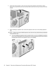
... the four silver Phillips screws that secure the fan to the chassis. 5. To install the fan assembly, reverse the removal procedure. Remove the computer access panel (Computer Access Panel on page 27). 2. Rear Chassis Fan 63 Prepare the computer for disassembly (Preparation for Disassembly on page 31...
... the four silver Phillips screws that secure the fan to the chassis. 5. To install the fan assembly, reverse the removal procedure. Remove the computer access panel (Computer Access Panel on page 27). 2. Rear Chassis Fan 63 Prepare the computer for disassembly (Preparation for Disassembly on page 31...

Service Reference Guide: HP Compaq dx2400 Business PC
Page 71
... connected to the system board, noting their location for Disassembly on page 31). 3. When reinstalling the system board, first insert the I /O panel from the rear of the computer to the chassis. 7. Disconnect all expansion boards (Expansion Cards on page 60). 6. Lift the system board out of the ...secure the system board to disengage the I /O panel back into the slots in the BIOS. Slide the system board toward the front of the chassis. 8. NOTE: When replacing the system board, you must change the chassis serial number in the rear of the computer. System Board 1. Remove the...
... connected to the system board, noting their location for Disassembly on page 31). 3. When reinstalling the system board, first insert the I /O panel from the rear of the computer to the chassis. 7. Disconnect all expansion boards (Expansion Cards on page 60). 6. Lift the system board out of the ...secure the system board to disengage the I /O panel back into the slots in the BIOS. Slide the system board toward the front of the chassis. 8. NOTE: When replacing the system board, you must change the chassis serial number in the rear of the computer. System Board 1. Remove the...

Service Reference Guide: HP Compaq dx2400 Business PC
Page 100
... choke (2nd) L4 USB rear port choke (3rd) L5 USB front port choke (2nd) P1 P/S connector (20 or 24 pin) P2 Second P/S connector (as required) P3 Processor 12V header P4 ... header P19 SPDIF internal output header P20 Primary IDE connector P21 Secondary IDE/MultiBay connector P22 Header for NEWCARD P23 Header for front panel audio P24 Header for front panel USB P25 Internal USB connector 1 P26 Internal USB connector 2 P27 MultiBay header P29 SCSI LED connector P30 PCI extender slot (female) P40...
... choke (2nd) L4 USB rear port choke (3rd) L5 USB front port choke (2nd) P1 P/S connector (20 or 24 pin) P2 Second P/S connector (as required) P3 Processor 12V header P4 ... header P19 SPDIF internal output header P20 Primary IDE connector P21 Secondary IDE/MultiBay connector P22 Header for NEWCARD P23 Header for front panel audio P24 Header for front panel USB P25 Internal USB connector 1 P26 Internal USB connector 2 P27 MultiBay header P29 SCSI LED connector P30 PCI extender slot (female) P40...
Service Reference Guide: HP Compaq dx2400 Business PC
Page 107
... 59 processor removal and replacement 61 product ID location 26 R rear chassis fan removal and replacement 63 reference designators 92 removal and replacement access panel 31 battery 66 expansion cards 39 front bezel 32 front USB panel 58 heatsink 60 memory 36 power supply 64 power switch/LED ...pinouts 16 hard drive characteristics 15 pin assignments 77 power cable pinouts 16 screws, correct size 24 security cable lock 28 HP Business PC Security Lock 29 padlock 28 serial interface pin assignments 71 serial number location 26 service considerations 23 software backing up 13 servicing computer...
... 59 processor removal and replacement 61 product ID location 26 R rear chassis fan removal and replacement 63 reference designators 92 removal and replacement access panel 31 battery 66 expansion cards 39 front bezel 32 front USB panel 58 heatsink 60 memory 36 power supply 64 power switch/LED ...pinouts 16 hard drive characteristics 15 pin assignments 77 power cable pinouts 16 screws, correct size 24 security cable lock 28 HP Business PC Security Lock 29 padlock 28 serial interface pin assignments 71 serial number location 26 service considerations 23 software backing up 13 servicing computer...

