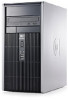
Quick Setup and Getting Started Guide
Page 22
... required airflow 2. Cause Solution System volume may be set correctly. 3. Make sure the external speakers are properly connected and powered on memory. Cannot remove computer cover or access panel. Cause Solution Smart Cover Lock, featured on all vented sides of forgotten password, power loss, or computer malfunction. Order PN 166527-001 for the...
Quick Setup and Getting Started Guide Enhanced for Accessibility
Page 22
... 1 Solving General Problems (continued) There is no sound or sound volume is not muted (this setting does not affect the external speakers). 2. Cannot remove computer cover or access panel. Cause Solution Smart Cover Lock, featured on the hard drive. The Smart Cover FailSafe Key, a device for the screwdriver bit key. You will need...
Hardware Reference Guide - dc5850 Microtower Models
Page 5
Table of contents 1 Product Features Standard Configuration Features ...1 Front Panel Components ...2 Media Card Reader Components ...3 Rear Panel Components ...4 Keyboard ...5 Using the Windows Logo Key 6 Serial Number Location ...7 2 Hardware Upgrades Serviceability Features ...8 Warnings and Cautions ...8 Removing the Computer Access Panel 9 Replacing the Computer Access Panel 10 Removing the Front Bezel ...11 Replacing the Front Bezel ...12 Installing Additional Memory ...13...
Hardware Reference Guide - dc5850 Microtower Models
Page 15
Loosen the captive thumbscrew (1) that prohibit opening the computer. 2. Slide the access panel back (2) about 1.3 cm (1/2 inch), then lift it off any external devices. 4. Figure 2-1 Removing the Computer Access Panel ENWW Removing the Computer Access Panel 9 Turn off the computer properly through the operating system, then turn off the unit. You must disconnect the power cord to avoid damage...
Hardware Reference Guide - dc5850 Microtower Models
Page 17
..., voltage is plugged into an active AC outlet. Disconnect the power cord from the computer. 3. Removing the Front Bezel 1. Figure 2-3 Removing the Front Bezel ENWW Removing the Front Bezel 11 Turn off the computer properly through the operating system, then turn off any ...external devices. Remove/disengage any security devices that prohibit opening the computer. 2. CAUTION: Regardless of the bezel and the single latch on the system board as long as diskettes or compact discs, from the power outlet and disconnect any external devices. 4. Remove the computer access panel. 6.
Hardware Reference Guide - dc5850 Microtower Models
Page 21
...● In either mode, the maximum operational speed is determined by briefly touching a grounded metal object. WARNING! Adding or removing memory modules while voltage is present may cause irreparable damage to prevent corrosion and/or oxidation resulting from the power outlet and ... off the computer properly through the operating system, then turn off any external devices. 4. Remove the computer access panel. 6. The memory module sockets have gold-plated metal contacts. Remove all removable media, such as the computer is plugged into an active AC outlet. Static electricity can ...
Hardware Reference Guide - dc5850 Microtower Models
Page 22
...the memory capacity of the memory module socket (1), and insert the memory module into the socket, ensuring that were disengaged when the access panel was removed. 16 Chapter 2 Hardware Upgrades ENWW Reconnect the power cord and any additional modules. 10. Match the notch on the module ...with the tab on page 14 for more information. 8. Replace the computer access panel. 11. Lock any security devices that the module is fully inserted and...
Hardware Reference Guide - dc5850 Microtower Models
Page 23
...the power cord to avoid damage to 17.46 cm (6.875 inches) in the PCI Express x16 expansion slot. ENWW Removing or Installing an Expansion Card 17 Remove the computer access panel. Remove/disengage any security devices that can install a PCI Express x1, x4, x8, or x16 expansion card in length. ...to the internal components of the power-on state, voltage is plugged into an active AC outlet. CAUTION: Regardless of the computer. 5. Remove all removable media, such as the system is always present on the system board as long as diskettes or compact discs, from the power outlet ...
Hardware Reference Guide - dc5850 Microtower Models
Page 27
13. Reconnect the power cord and any security devices that were disengaged when the access panel was removed. 17. Drive Positions Figure 2-14 Drive Positions 1 Two 5.25-inch external drive bays for optional drives (optical drives shown) 2 One 3.5-inch ... needed . ENWW Drive Positions 21 Connect external cables to the Computer Setup (F10) Utility Guide for instructions on the computer. 16. Replace the computer access panel. 15. Refer to the installed card, if needed . 14. Reconfigure the computer, if necessary. Lock any external devices, then turn on using Computer...
Hardware Reference Guide - dc5850 Microtower Models
Page 31
...-inch optical drive, disconnect the power cable (1) and data cable (2) from the power outlet and disconnect any external devices. Remove all removable media, such as the system is plugged into an active AC outlet. Disconnect the power cord from the back of the drive. Figure 2-17 Disconnecting ... long as diskettes or compact discs, from the computer. 1. You must disconnect the power cord to avoid damage to the internal components of the computer. 5. Remove the access panel and front bezel. 6. Disconnect the drive cables, as indicated in the following illustrations...
Hardware Reference Guide - dc5850 Microtower Models
Page 36
... on the system board labeled SATA1. b. Reconnect the power cord and any security devices that were disengaged when the access panel was removed. 30 Chapter 2 Hardware Upgrades ENWW Replace the front bezel and computer access panel. 7. If you are installing a diskette drive, connect it to the white SATA connector on the computer. 8. Connect a second optical...
Hardware Reference Guide - dc5850 Microtower Models
Page 37
... operating system, software drivers, and any security devices that prohibit opening the computer. 2. Figure 2-26 Disconnecting the Hard Drive Cables ENWW Installing Additional Drives 31 Remove the access panel and front bezel. 6. Remove/disengage any software applications that were preinstalled on the system board as long as diskettes or compact discs, from the computer...
Hardware Reference Guide - dc5850 Microtower Models
Page 40
If installing a new drive, connect the opposite end of the hard drive. Replace the front bezel and computer access panel. 7. NOTE: If you are replacing the primary hard drive, use the Recovery Disc Set to the next available (unpopulated) SATA ...adding a second hard drive, connect the data cable to restore the operating system, software drivers, and any software applications that were disengaged when the access panel was removed. A sharp bend can break the internal wires. 4. Route the power and data cables in ) radius. 3. Lock any external devices, then turn...
Hardware Reference Guide - dc5850 Microtower Models
Page 47
...! There is not handled properly. HP encourages customers to recycle used when the computer is plugged into a live AC wall socket. Remove the computer access panel. 6. To reduce the risk of the computer. 5. You must disconnect the power cord to avoid damage to the internal components of... personal injury: Do not attempt to AC power. Remove all removable media, such as the system is NOT connected to recharge the battery. When ...
Hardware Reference Guide - dc5850 Microtower Models
Page 49
Figure B-3 Removing a Coin Cell Battery (Type 3) NOTE: After the battery has been replaced, use the following steps to the Computer Setup (F10) Utility Guide. 11. Refer to complete this procedure. 8. Lock any special system setups using Computer Setup. Reset the date and time, your passwords, and any security devices that were disengaged when the access panel was removed. ENWW 43 Replace the computer access panel. 9. b. Insert the new battery and position the clip back into place. Plug in the computer and turn on power to the computer. 10.
Hardware Reference Guide - dc5850 Microtower Models
Page 55
... ventilation slots on the monitor with a soft, damp cloth as this also restricts airflow. ● Never operate the computer with the access panel or any of the expansion card slot covers removed. ● Do not stack computers on top of each other or place computers so near each other that they are subject...
Hardware Reference Guide - dc5850 Microtower Models
Page 57
...access panel locking and unlocking 44 removing 9 replacing 10 audio connectors 2, 4 B battery replacement 41 C computer operating guidelines 49 connecting drive cables 22 connector DVI-D monitor 4 VGA monitor 4 F front bezel removing 11 removing blanks 28 replacing 12 security 47 front panel components 2 G guide screws 22 H hard drive installing 33 removing... 4 line-out connector 4 ENWW locks cable lock 44 HP Business PC Security Lock 45 padlock 45 M media card reader features 3 installing 28 removing 25 memory installing 13 populating sockets 14 specifications 13 microphone connector 2 ...
Hardware Reference Guide - dc5850 Microtower Models
Page 58
removing battery 41 computer access panel 9 diskette drive 25 expansion card 17 expansion slot cover 18 front bezel 11 hard drive 31 media card reader 25 optical drive 25 PCI card 19 PCI Express card 19 S security cable lock 44 front bezel 47 HP Business PC Security Lock 45 padlock 45 serial connector 4 serial number location 7 shipping preparation 50 specifications computer 39 memory 13 system board drive connections 24 U unlocking access panel 44 USB ports front panel 2 rear panel 4 V ventilation guidelines 49 VGA monitor connector 4 W Windows Logo key 6 52 Index ENWW
Service Reference Guide: HP Compaq dc5850 Business PC
Page 246
...access panel removal and replacement 66 cable management 68 chassis, illustrated 53 disassembly preparation 61 expansion cards removal and replacement 72 external security 62 fan shroud removal and replacement 93 fan/air baffle removal and replacement 94 front bezel removal and replacement 67 front USB panel removal and replacement 95 heatsink removal...ordering FailSafe Key 47 overheating, prevention 55 P password changing 43 clearing 44 deleting 43 power-on 42 security 41 setup 41, 42 PC deployment 22 PCI card 72, 74, 123, 125 PCI Express card 72, 74, 123, 125 PCI Express pin assignments 169 ...
Service Reference Guide: HP Compaq dc5850 Business PC
Page 248
... Intel vPro technology 29 PC deployment 23 Proactive Change Notification 31 Remote ROM Flash 32 replicating setup 35 ROM Flash 32 software support 39 236 Index entering 42 setting 41 SFF battery removal and replacement 160 cable connections 128 cable management 127 cable routing 149 chassis, illustrated 52 computer access panel removal and replacement 114...