
Hardware Maintenance Manual
Page 3
.... Customer agrees to change without problems or interruptions. Further, Customer agrees to supply any reproducible errors, or (ii) to refund to use the Cisco software ("Software") in object code form solely on a straight-line basis. The information in which (1) has been altered, except as set forth in subparagraph (c) of an uplift, or (7) has been misapplied. Cisco 4000 Series Hardware Installation and Maintenance Copyright ©...
.... Customer agrees to change without problems or interruptions. Further, Customer agrees to supply any reproducible errors, or (ii) to refund to use the Cisco software ("Software") in object code form solely on a straight-line basis. The information in which (1) has been altered, except as set forth in subparagraph (c) of an uplift, or (7) has been misapplied. Cisco 4000 Series Hardware Installation and Maintenance Copyright ©...

Hardware Maintenance Manual
Page 6
...Power Supply 3-20 Making Final Connections to the Router 3-22 Chapter 4 Troubleshooting the Initial Hardware Configuration 4-1 Problem Solving 4-1 Troubleshooting the Power and Cooling Systems 4-2 Troubleshooting the Network Processor Modules and Cables 4-2 Environmental Reporting Features 4-3 Reading Front-Panel LED Indicators 4-3 System LED Operation 4-3 Reading Network Processor Module LED Indicators 4-4 Ethernet Network Processor Module LED Indicators 4-4 Token Ring Network Processor Module LED Indicators 4-5 Four Port Serial Module Indicators 4-6 Dual Serial Network Processor Module LED...
...Power Supply 3-20 Making Final Connections to the Router 3-22 Chapter 4 Troubleshooting the Initial Hardware Configuration 4-1 Problem Solving 4-1 Troubleshooting the Power and Cooling Systems 4-2 Troubleshooting the Network Processor Modules and Cables 4-2 Environmental Reporting Features 4-3 Reading Front-Panel LED Indicators 4-3 System LED Operation 4-3 Reading Network Processor Module LED Indicators 4-4 Ethernet Network Processor Module LED Indicators 4-4 Token Ring Network Processor Module LED Indicators 4-5 Four Port Serial Module Indicators 4-6 Dual Serial Network Processor Module LED...

Hardware Maintenance Manual
Page 9
... 2-32 Cisco 4000 Series Chassis-Front Panel 1-2 Cisco 4000 Series Memory Systems and Software Images 1-4 Installation Checklist 2-5 Router-Rear View Showing Slot Numbering and Interface Ports 2-7 Router-Rear View Showing Serial Port Unit Numbering 2-8 Slot Filler Panel 2-9 Ethernet Network Processor Module with AUI and 10BaseT Connectors 2-11 Single-Port Ethernet Network Processor Module 10BaseT Port Connection 2-11 Single-Port Ethernet Network Processor Module AUI Port Connection 2-12 Extending the Transition Cable from the Ethernet Port 2-12 Dual-Port Ethernet Network Processor Module with...
... 2-32 Cisco 4000 Series Chassis-Front Panel 1-2 Cisco 4000 Series Memory Systems and Software Images 1-4 Installation Checklist 2-5 Router-Rear View Showing Slot Numbering and Interface Ports 2-7 Router-Rear View Showing Serial Port Unit Numbering 2-8 Slot Filler Panel 2-9 Ethernet Network Processor Module with AUI and 10BaseT Connectors 2-11 Single-Port Ethernet Network Processor Module 10BaseT Port Connection 2-11 Single-Port Ethernet Network Processor Module AUI Port Connection 2-12 Extending the Transition Cable from the Ethernet Port 2-12 Dual-Port Ethernet Network Processor Module with...

Hardware Maintenance Manual
Page 10
... AC-Input Power Supply-Rear View 3-20 DC-Input Power Supply Connections 3-21 Cisco 4000 Series-Front Panel Indicators 4-3 Dual-Port Ethernet Network Processor Module LEDs 4-4 Single-Port Ethernet Network Processor Module LEDs 4-4 Token Ring Module Network Connector 4-5 Four-Port Serial Network Processor Module Ports 4-6 G.703/G.704 Serial Network Processor Module Ports (DB-15) 4-6 Serial Port Labeled V2 4-7 Dual Serial Network Processor Module-Top View 4-8 Dual Serial Port LED Card-Side View 4-8 Dual-Attachment Single-Mode FDDI Module-End View 4-9 x Cisco 4000 Series Hardware Installation and...
... AC-Input Power Supply-Rear View 3-20 DC-Input Power Supply Connections 3-21 Cisco 4000 Series-Front Panel Indicators 4-3 Dual-Port Ethernet Network Processor Module LEDs 4-4 Single-Port Ethernet Network Processor Module LEDs 4-4 Token Ring Module Network Connector 4-5 Four-Port Serial Network Processor Module Ports 4-6 G.703/G.704 Serial Network Processor Module Ports (DB-15) 4-6 Serial Port Labeled V2 4-7 Dual Serial Network Processor Module-Top View 4-8 Dual Serial Port LED Card-Side View 4-8 Dual-Attachment Single-Mode FDDI Module-End View 4-9 x Cisco 4000 Series Hardware Installation and...

Hardware Maintenance Manual
Page 11
... Tray Removal for Chassis Without a Safety Latch 5-4 Typical Cisco 4000 Series Component Tray-Cisco 4000-M Shown 5-5 Network Processor Module Locations 5-6 Cisco 4000-M SIMM Locations 5-7 Cisco 4500-M and Cisco 4700 SIMM Locations 5-8 Cisco 4000 Series Main Memory SIMM 5-8 Removing Main Memory SIMMs 5-10 Installing Main Memory SIMMs 5-12 Inserting Shared-Memory SIMMs 5-15 Removing the Boot Helper Flash Memory SIMM 5-16 Inserting Flash-Memory SIMMs 5-18 Boot ROMs Locations 5-19 Dual Serial EIA/TIA-232 Cable Assembly...
... Tray Removal for Chassis Without a Safety Latch 5-4 Typical Cisco 4000 Series Component Tray-Cisco 4000-M Shown 5-5 Network Processor Module Locations 5-6 Cisco 4000-M SIMM Locations 5-7 Cisco 4500-M and Cisco 4700 SIMM Locations 5-8 Cisco 4000 Series Main Memory SIMM 5-8 Removing Main Memory SIMMs 5-10 Installing Main Memory SIMMs 5-12 Inserting Shared-Memory SIMMs 5-15 Removing the Boot Helper Flash Memory SIMM 5-16 Inserting Flash-Memory SIMMs 5-18 Boot ROMs Locations 5-19 Dual Serial EIA/TIA-232 Cable Assembly...

Hardware Maintenance Manual
Page 15
... physical specifications. • Chapter 2, "Preparing for Installation," includes safety recommendations, tools and equipment, site requirements, an installation checklist, console and auxiliary port cable connection considerations, network connection considerations, and instructions for inspecting the new system. • Chapter 3, "Installing the Router," includes instructions for the router installer, who should be more up to the appropriate software publication. To order UniverCD, contact your warranty package. Use this publication follow: • Chapter 1, "Cisco...
... physical specifications. • Chapter 2, "Preparing for Installation," includes safety recommendations, tools and equipment, site requirements, an installation checklist, console and auxiliary port cable connection considerations, network connection considerations, and instructions for inspecting the new system. • Chapter 3, "Installing the Router," includes instructions for the router installer, who should be more up to the appropriate software publication. To order UniverCD, contact your warranty package. Use this publication follow: • Chapter 1, "Cisco...

Hardware Maintenance Manual
Page 16
... Hardware Configuration," includes a troubleshooting overview, problem-solving instructions, environmental reporting features, and understanding front-panel and network-processor module LED indicators. • Chapter 5, "Maintaining and Upgrading the Router," includes instructions for opening the chassis, replacing or adding network processor modules, and replacing single in-line memory modules (SIMMs). • Appendix A, "Cabling Specifications," provides cable illustrations, cable pinouts, and signal descriptions for the console and auxiliary ports, synchronous serial cables, and Ethernet...
... Hardware Configuration," includes a troubleshooting overview, problem-solving instructions, environmental reporting features, and understanding front-panel and network-processor module LED indicators. • Chapter 5, "Maintaining and Upgrading the Router," includes instructions for opening the chassis, replacing or adding network processor modules, and replacing single in-line memory modules (SIMMs). • Appendix A, "Cabling Specifications," provides cable illustrations, cable pinouts, and signal descriptions for the console and auxiliary ports, synchronous serial cables, and Ethernet...

Hardware Maintenance Manual
Page 28
... a copy of your router. Use the Installation Checklist to the router. Site Log entries might need the following tools and equipment for the installation of the router: • ESD cord and wrist strap • Screwdrivers, Number 1 and Number 2 Phillips • One serial port adapter cable for multimode Fiber Distributed Data Interface (FDDI) connections. 2-6 Cisco 4000 Series Hardware Installation and Maintenance Removal or replacement of 1 bits per time unit in a data stream, called ones...
... a copy of your router. Use the Installation Checklist to the router. Site Log entries might need the following tools and equipment for the installation of the router: • ESD cord and wrist strap • Screwdrivers, Number 1 and Number 2 Phillips • One serial port adapter cable for multimode Fiber Distributed Data Interface (FDDI) connections. 2-6 Cisco 4000 Series Hardware Installation and Maintenance Removal or replacement of 1 bits per time unit in a data stream, called ones...

Hardware Maintenance Manual
Page 32
...-port Ethernet network processor module is not supported on the desired interface. The syntax of the media command follows: media-type aui media-type aui 10baset The following sections describe the two types of Ethernet network processor modules: single-port and dual-port modules. Enter the media command in the router's configuration file to make the connection. Edit with CTRL/Z interface ethernet 0 media-type aui ^z router# write memory Refer to the router software publications for more information on the module can be used...
...-port Ethernet network processor module is not supported on the desired interface. The syntax of the media command follows: media-type aui media-type aui 10baset The following sections describe the two types of Ethernet network processor modules: single-port and dual-port modules. Enter the media command in the router's configuration file to make the connection. Edit with CTRL/Z interface ethernet 0 media-type aui ^z router# write memory Refer to the router software publications for more information on the module can be used...

Hardware Maintenance Manual
Page 37
... as a DB-25. (See Figure 2-13.) The router Console and Auxiliary ports also use EIA/TIA-232 connections; The network end of the adapter cable is commonly used. Preparing for each serial interface type; All serial signals are also valid for EIA/TIA-449 shown in Table 2-4. however, the serial module ports support synchronous connections, and the console and auxiliary ports support asynchronous connections. generally, the slower the baud rate, the greater...
... as a DB-25. (See Figure 2-13.) The router Console and Auxiliary ports also use EIA/TIA-232 connections; The network end of the adapter cable is commonly used. Preparing for each serial interface type; All serial signals are also valid for EIA/TIA-449 shown in Table 2-4. however, the serial module ports support synchronous connections, and the console and auxiliary ports support asynchronous connections. generally, the slower the baud rate, the greater...

Hardware Maintenance Manual
Page 43
... Dual Serial Network Processor Module Jumpers, J4 and J5-NRZI Setting J5 J4 Pin 1 H1125a Port 1 Port 0 You must use a special serial cable to connect the router to the software publications. Note that the cables for Installation 2-21 Network Connection Considerations If the network processor module is operating as DTE in NRZI mode, the sense of the dte-invert-timing command must be configured with the system. Figure 2-23 Router Serial Cable Connections Serial port 50-pin connector Serial transition cable Chassis H1037a...
... Dual Serial Network Processor Module Jumpers, J4 and J5-NRZI Setting J5 J4 Pin 1 H1125a Port 1 Port 0 You must use a special serial cable to connect the router to the software publications. Note that the cables for Installation 2-21 Network Connection Considerations If the network processor module is operating as DTE in NRZI mode, the sense of the dte-invert-timing command must be configured with the system. Figure 2-23 Router Serial Cable Connections Serial port 50-pin connector Serial transition cable Chassis H1037a...
Hardware Maintenance Manual
Page 44
... interface types, if your cable lengths exceed the standard recommendations, faster speeds might not work. Inverting the Clock Signal on the Four-Port Serial Module Systems that follows, the serial 0 port is configured to accept the internal clock signal: interface serial 0 dce-terminal-timing-enable 2-22 Cisco 4000 Series Hardware Installation and Maintenance The default operation on a DCE interface is for DTE operation. In the following sections describe the commands for configuring...
... interface types, if your cable lengths exceed the standard recommendations, faster speeds might not work. Inverting the Clock Signal on the Four-Port Serial Module Systems that follows, the serial 0 port is configured to accept the internal clock signal: interface serial 0 dce-terminal-timing-enable 2-22 Cisco 4000 Series Hardware Installation and Maintenance The default operation on a DCE interface is for DTE operation. In the following sections describe the commands for configuring...

Hardware Maintenance Manual
Page 45
... transmitted data. Configuring NRZI Format on the Four-Port Serial Module All Cisco 4000 series router serial interfaces support CRC-CCITT, a 16-bit cyclic redundancy check (CRC). Use the no transition. NRZ format, which transmits streams of check digits per frame that a transmission error occurred and sends a request to the sender to calculate the FCS. The no dce-terminal-timing-enable command. The designator 16 indicates the number...
... transmitted data. Configuring NRZI Format on the Four-Port Serial Module All Cisco 4000 series router serial interfaces support CRC-CCITT, a 16-bit cyclic redundancy check (CRC). Use the no transition. NRZ format, which transmits streams of check digits per frame that a transmission error occurred and sends a request to the sender to calculate the FCS. The no dce-terminal-timing-enable command. The designator 16 indicates the number...
Hardware Maintenance Manual
Page 47
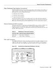
... one card fitting on the module's top card. Network Connection Considerations Fiber Distributed Data Interface Connections Multimode FDDI network processor modules provide either a dual-attachment station (DAS) or a single-attachment station (SAS). If the DAS option is included, the PHY-B port is greater than the maximum distance shown, significant signal loss can result. The ports accept standard 8.7 to 10/125-micron single-mode fiber-optic cable, supporting connections at...
... one card fitting on the module's top card. Network Connection Considerations Fiber Distributed Data Interface Connections Multimode FDDI network processor modules provide either a dual-attachment station (DAS) or a single-attachment station (SAS). If the DAS option is included, the PHY-B port is greater than the maximum distance shown, significant signal loss can result. The ports accept standard 8.7 to 10/125-micron single-mode fiber-optic cable, supporting connections at...
Hardware Maintenance Manual
Page 61
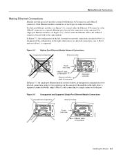
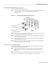
.... the module on the right shows a supported connection with a single 10BaseT cable connecting to transceiver Installing the Router 3-3 In Figure 3-2, the configuration on the left shows an unsupported configuration of connector interface. For dual-port Ethernet modules (see Figure 3-3), connect either the Ethernet AUI connector or the 10BaseT connector on a specific Ethernet port, but not both on the same module. Figure 3-3 Unsupported and Supported Single-Port Ethernet Module Connections Unsupported configuration Ethernet module H1570a AUI 10BASE-T AUX Router (rear...
.... the module on the right shows a supported connection with a single 10BaseT cable connecting to transceiver Installing the Router 3-3 In Figure 3-2, the configuration on the left shows an unsupported configuration of connector interface. For dual-port Ethernet modules (see Figure 3-3), connect either the Ethernet AUI connector or the 10BaseT connector on a specific Ethernet port, but not both on the same module. Figure 3-3 Unsupported and Supported Single-Port Ethernet Module Connections Unsupported configuration Ethernet module H1570a AUI 10BASE-T AUX Router (rear...
Hardware Maintenance Manual
Page 62
... 10BaseT cable to the Router." Ensure that orientation. Step 3 On a dual-port Ethernet network interface module, repeat steps 1 and 2 for the second port. Making Serial Connections The 60-pin DB-60 connector is standard on the four-port serial network processor module; Do not force the cable into the connector upside down . Making Network Connections Making Ethernet AUI Connections Follow these steps to the channel service unit/data service unit (CSU/DSU) or modem. 3-4 Cisco 4000 Series Hardware Installation and...
... 10BaseT cable to the Router." Ensure that orientation. Step 3 On a dual-port Ethernet network interface module, repeat steps 1 and 2 for the second port. Making Serial Connections The 60-pin DB-60 connector is standard on the four-port serial network processor module; Do not force the cable into the connector upside down . Making Network Connections Making Ethernet AUI Connections Follow these steps to the channel service unit/data service unit (CSU/DSU) or modem. 3-4 Cisco 4000 Series Hardware Installation and...

Hardware Maintenance Manual
Page 66
... Access Integrated Switched Digital Networks (ISDN), each at the S reference point. Caution To prevent damage to the system, make certain you connect the BRI cable to the BRI connector only and not to -point mode only. 3-8 Cisco 4000 Series Hardware Installation and Maintenance Testing the BRI Interface An external loopback RJ-45 connector, useful for use the test interface command to determine that provides all of the hardware necessary to allow connection...
... Access Integrated Switched Digital Networks (ISDN), each at the S reference point. Caution To prevent damage to the system, make certain you connect the BRI cable to the BRI connector only and not to -point mode only. 3-8 Cisco 4000 Series Hardware Installation and Maintenance Testing the BRI Interface An external loopback RJ-45 connector, useful for use the test interface command to determine that provides all of the hardware necessary to allow connection...
Hardware Maintenance Manual
Page 71
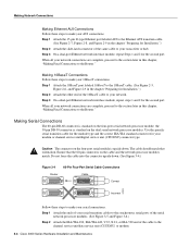
... bypass interface cable to PHY- Step 5 When all your network connections are complete, proceed to the section "Making Final Connections to the optical bypass switch. Installing the Router 3-13 Step 1 Connect one end of the optical bypass interface cable to the Router" later in this chapter. B transmit port labeled XMTR. B receive port, labeled RCVR on the module panel. (See Figure 3-12.) Figure 3-12 Single-Mode Dual-Attachment FDDI Connections To...
... bypass interface cable to PHY- Step 5 When all your network connections are complete, proceed to the section "Making Final Connections to the optical bypass switch. Installing the Router 3-13 Step 1 Connect one end of the optical bypass interface cable to the Router" later in this chapter. B transmit port labeled XMTR. B receive port, labeled RCVR on the module panel. (See Figure 3-12.) Figure 3-12 Single-Mode Dual-Attachment FDDI Connections To...
Hardware Maintenance Manual
Page 118
... displayed on a network server. (See Table B-3.) To change the configuration register while running the IOS software, follow : • Recover a lost password. • Change the console baud rate. • Enable or disable the Break function. • Manually boot the operating system using the b command at the ROM monitor prompt. • Force the router to boot automatically its configuration file in NVRAM. B-2 Cisco 4000 Series Hardware Installation and Maintenance Virtual Configuration Register Settings Changing Configuration Register Settings Some common...
... displayed on a network server. (See Table B-3.) To change the configuration register while running the IOS software, follow : • Recover a lost password. • Change the console baud rate. • Enable or disable the Break function. • Manually boot the operating system using the b command at the ROM monitor prompt. • Force the router to boot automatically its configuration file in NVRAM. B-2 Cisco 4000 Series Hardware Installation and Maintenance Virtual Configuration Register Settings Changing Configuration Register Settings Some common...

Hardware Maintenance Manual
Page 141
...45 A-20 serial cable A-3-A-18 Token Ring A-21 V.35 dual-port A-10 four-port A-11 X.21 dual-port A-14 four-port A-15 polarity, Ethernet LED 4-5 port locations 2-7 software configuration, serial 4-8 power LED indication 3-22 light 4-3 specifications 1-3 supply features 2-4 system, troubleshooting 4-2 preparing for installation 2-1 to make connections 2-7 preventing ESD damage 2-3 preventive site configuration 2-4 printing summary of ROM monitor commands problem indications 4-3 temperature 4-3 problem solving 4-1 processor specifications 1-3 protocol analyzer, attaching 2-9 publications, ordering...
...45 A-20 serial cable A-3-A-18 Token Ring A-21 V.35 dual-port A-10 four-port A-11 X.21 dual-port A-14 four-port A-15 polarity, Ethernet LED 4-5 port locations 2-7 software configuration, serial 4-8 power LED indication 3-22 light 4-3 specifications 1-3 supply features 2-4 system, troubleshooting 4-2 preparing for installation 2-1 to make connections 2-7 preventing ESD damage 2-3 preventive site configuration 2-4 printing summary of ROM monitor commands problem indications 4-3 temperature 4-3 problem solving 4-1 processor specifications 1-3 protocol analyzer, attaching 2-9 publications, ordering...


