
Hardware Maintenance Manual
Page 6
... 5-6 Replacing Main Memory SIMMs 5-8 Removing Main Memory SIMMS 5-9 Installing Main Memory SIMMs 5-11 Replacing Shared-Memory SIMMs 5-13 Inserting Shared-Memory SIMMs 5-14 Removing the Cisco 4500-M and Cisco 4700 Boot Helper Flash Memory SIMM 5-16 Installing Flash-Memory SIMMs 5-17 Replacing Boot ROMs in the...
... 5-6 Replacing Main Memory SIMMs 5-8 Removing Main Memory SIMMS 5-9 Installing Main Memory SIMMs 5-11 Replacing Shared-Memory SIMMs 5-13 Inserting Shared-Memory SIMMs 5-14 Removing the Cisco 4500-M and Cisco 4700 Boot Helper Flash Memory SIMM 5-16 Installing Flash-Memory SIMMs 5-17 Replacing Boot ROMs in the...

Hardware Maintenance Manual
Page 7
... Port Pinout A-21 BRI Pinout A-22 Channelized T1 Pinouts A-22 Channelized E1 Pinouts A-23 Appendix B Cisco 4000 Series Virtual Configuration Register B-1 Virtual Configuration Register Settings B-1 Changing Configuration Register Settings B-2 Configuring the Boot Field B-3 ...Enabling Booting from Flash Memory B-6 Appendix C Cisco 4000-M ROM Monitor C-1 Entering the Cisco 4000-M ROM Monitor Program C-1 Available ROM Monitor Commands C-2 Appendix D Cisco 4500-M and Cisco 4700 ROM Monitor D-1 Entering the ROM Monitor Program D-1 Available ROM Monitor ...
... Port Pinout A-21 BRI Pinout A-22 Channelized T1 Pinouts A-22 Channelized E1 Pinouts A-23 Appendix B Cisco 4000 Series Virtual Configuration Register B-1 Virtual Configuration Register Settings B-1 Changing Configuration Register Settings B-2 Configuring the Boot Field B-3 ...Enabling Booting from Flash Memory B-6 Appendix C Cisco 4000-M ROM Monitor C-1 Entering the Cisco 4000-M ROM Monitor Program C-1 Available ROM Monitor Commands C-2 Appendix D Cisco 4500-M and Cisco 4700 ROM Monitor D-1 Entering the ROM Monitor Program D-1 Available ROM Monitor ...

Hardware Maintenance Manual
Page 11
... Tray Removal for Chassis With a Safety Latch 5-3 Component Tray Removal for Chassis Without a Safety Latch 5-4 Typical Cisco 4000 Series Component Tray-Cisco 4000-M Shown 5-5 Network Processor Module Locations 5-6 Cisco 4000-M SIMM Locations 5-7 Cisco 4500-M and Cisco 4700 SIMM Locations 5-8 Cisco 4000 Series Main Memory SIMM 5-8 Removing Main Memory SIMMs 5-10 Installing Main Memory SIMMs 5-12 Inserting Shared...
... Tray Removal for Chassis With a Safety Latch 5-3 Component Tray Removal for Chassis Without a Safety Latch 5-4 Typical Cisco 4000 Series Component Tray-Cisco 4000-M Shown 5-5 Network Processor Module Locations 5-6 Cisco 4000-M SIMM Locations 5-7 Cisco 4500-M and Cisco 4700 SIMM Locations 5-8 Cisco 4000 Series Main Memory SIMM 5-8 Removing Main Memory SIMMs 5-10 Installing Main Memory SIMMs 5-12 Inserting Shared...

Hardware Maintenance Manual
Page 13
... Table A-12 Table A-13 Table A-14 Table A-15 Table A-16 Table A-17 Table A-18 Table A-19 Table A-20 Cisco 4000 Series Physical Specifications 1-3 Cisco 4000 Series Processor and Memory Specifications 1-3 Unit Numbering for Dual Serial, Ethernet, and Token Ring Modules 2-7 Unit Numbering Addresses for...3-10 Four Port Serial Network Processor Module LED Indicators 4-7 Dual Serial Network Processor Module LED Indicators 4-9 Cisco 4000-M Console and Auxiliary Port Signals A-2 Cisco 4500-M and Cisco 4700 Console and Auxiliary Port Signals A-2 Dual Serial Module EIA/TIA-232 DTE and DCE Serial Cable ...
... Table A-12 Table A-13 Table A-14 Table A-15 Table A-16 Table A-17 Table A-18 Table A-19 Table A-20 Cisco 4000 Series Physical Specifications 1-3 Cisco 4000 Series Processor and Memory Specifications 1-3 Unit Numbering for Dual Serial, Ethernet, and Token Ring Modules 2-7 Unit Numbering Addresses for...3-10 Four Port Serial Network Processor Module LED Indicators 4-7 Dual Serial Network Processor Module LED Indicators 4-9 Cisco 4000-M Console and Auxiliary Port Signals A-2 Cisco 4500-M and Cisco 4700 Console and Auxiliary Port Signals A-2 Dual Serial Module EIA/TIA-232 DTE and DCE Serial Cable ...

Hardware Maintenance Manual
Page 15
... information, refer to install and maintain the Cisco 4000-M, Cisco 4500-M, and the Cisco 4700. All Cisco technical documentation and additional literature are available on UniverCD, Cisco's online library of the Cisco 4000 Series Hardware Installation and Maintenance publication. Document...Document Organization The major sections of this publication to the appropriate software publication. Note To order UniverCD, Cisco's online library of the Cisco 4000 series features and physical specifications. • Chapter 2, "Preparing for Installation," includes safety recommendations, ...
... information, refer to install and maintain the Cisco 4000-M, Cisco 4500-M, and the Cisco 4700. All Cisco technical documentation and additional literature are available on UniverCD, Cisco's online library of the Cisco 4000 Series Hardware Installation and Maintenance publication. Document...Document Organization The major sections of this publication to the appropriate software publication. Note To order UniverCD, Cisco's online library of the Cisco 4000 series features and physical specifications. • Chapter 2, "Preparing for Installation," includes safety recommendations, ...

Hardware Maintenance Manual
Page 16
...ROM monitor and how it can save time by a vertical bar ( | ). You can be used. • Appendix D, "Cisco 4500-M and Cisco 4700 ROM Monitor," describes the Cisco 4500 ROM monitor. • Appendix E, "Operating Conditions for the United Kingdom," describes the operating conditions for use in the United Kingdom... Means the described actions saves time. Note Means reader take note. Samples use in this manual. xvi Cisco 4000 Series Hardware Installation and Maintenance Document Conventions This manual uses the following conventions to materials not contained in the European Community...
...ROM monitor and how it can save time by a vertical bar ( | ). You can be used. • Appendix D, "Cisco 4500-M and Cisco 4700 ROM Monitor," describes the Cisco 4500 ROM monitor. • Appendix E, "Operating Conditions for the United Kingdom," describes the operating conditions for use in the United Kingdom... Means the described actions saves time. Note Means reader take note. Samples use in this manual. xvi Cisco 4000 Series Hardware Installation and Maintenance Document Conventions This manual uses the following conventions to materials not contained in the European Community...

Hardware Maintenance Manual
Page 19
... Differences in Models of the Cisco 4700 reads Model 4700. CHAPTER 1 Cisco 4000 Series Overview The Cisco 4000 series comprises the Cisco 4000-M, the Cisco 4500-M, and the Cisco 4700. Performance is the key distinction between the Cisco 4000-M, Cisco 4500-M and Cisco 4700. Newer models have no...Motorola 68EC030 microprocessor. The rear label of the Cisco 4000-M reads Cisco 4000 M +, the rear label of the Cisco 4500-M reads Model 4500 M+, and the rear label of the Cisco 4000 Series The Cisco 4000-M, Cisco 4500-M, and Cisco 4700 are ready for external network hardware connections....
... Differences in Models of the Cisco 4700 reads Model 4700. CHAPTER 1 Cisco 4000 Series Overview The Cisco 4000 series comprises the Cisco 4000-M, the Cisco 4500-M, and the Cisco 4700. Performance is the key distinction between the Cisco 4000-M, Cisco 4500-M and Cisco 4700. Newer models have no...Motorola 68EC030 microprocessor. The rear label of the Cisco 4000-M reads Cisco 4000 M +, the rear label of the Cisco 4500-M reads Model 4500 M+, and the rear label of the Cisco 4000 Series The Cisco 4000-M, Cisco 4500-M, and Cisco 4700 are ready for external network hardware connections....

Hardware Maintenance Manual
Page 20
... panel of the single and dual Token Ring, dual Ethernet, and FDDI modules. 1-2 Cisco 4000 Series Hardware Installation and Maintenance Network processor modules can support two FDDI network processor modules. The Cisco 4500-M and Cisco 4700 can be placed in any of the three available positions in any two other types...) are not compatible with the Channelized T1/ISDN PRI network interface module (NP-CT1) or with any desired combination. Note The Cisco 4500-M and Cisco 4700 support all network processor modules except the single-port Ethernet network processor module and early versions of...
... panel of the single and dual Token Ring, dual Ethernet, and FDDI modules. 1-2 Cisco 4000 Series Hardware Installation and Maintenance Network processor modules can support two FDDI network processor modules. The Cisco 4500-M and Cisco 4700 can be placed in any of the three available positions in any two other types...) are not compatible with the Channelized T1/ISDN PRI network interface module (NP-CT1) or with any desired combination. Note The Cisco 4500-M and Cisco 4700 support all network processor modules except the single-port Ethernet network processor module and early versions of...

Hardware Maintenance Manual
Page 21
... to 95%, noncondensing Operating Temperature 32 to 104°F (0 to 16 MB 1. Table 1-2 Cisco 4000 Series Processor and Memory Specifications Description Processor Main Memory (DRAM)2 Cisco 4000-M Cisco 4500-M Cisco 4700 40-MHz Motorola 68EC030 100-MHz IDT Orion RISC1 133-MHz IDT Orion RISC 4, 8, ...FDDI, BRI, G.703, Channelized T1/PRI, Channelized T1/PRI, ATM EIA/TIA-2322, EIA/TIA-4491, V.35, X.21, NRZ/NRZI, DTE/DCE; Table 1-1 Cisco 4000 Series Physical Specifications Description Design Specification Dimensions (W x D x H) 17.6" x 17.7" x 3.4" (44.7 cm x 45 cm x 8.6 cm) Weight 24...
... to 95%, noncondensing Operating Temperature 32 to 104°F (0 to 16 MB 1. Table 1-2 Cisco 4000 Series Processor and Memory Specifications Description Processor Main Memory (DRAM)2 Cisco 4000-M Cisco 4500-M Cisco 4700 40-MHz Motorola 68EC030 100-MHz IDT Orion RISC1 133-MHz IDT Orion RISC 4, 8, ...FDDI, BRI, G.703, Channelized T1/PRI, Channelized T1/PRI, ATM EIA/TIA-2322, EIA/TIA-4491, V.35, X.21, NRZ/NRZI, DTE/DCE; Table 1-1 Cisco 4000 Series Physical Specifications Description Design Specification Dimensions (W x D x H) 17.6" x 17.7" x 3.4" (44.7 cm x 45 cm x 8.6 cm) Weight 24...
Hardware Maintenance Manual
Page 22
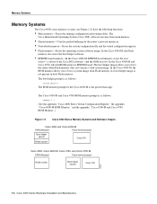
...: rommon 1 > (See the appendix "Cisco 4000 Series Virtual Configuration Register," the appendix "Cisco 4000-M ROM Monitor," and the appendix "Cisco 4500-M and Cisco 4700 ROM Monitor.") Figure 1-2 Cisco 4000 Series Memory Systems and Software Images Cisco 4000 and Cisco 4000-M EPROM-based Flash-memory based Boot helper (xboot) Cisco IOS ROM monitor Cisco 4500, Cisco 4500-M, Cisco 4700, and Cisco 4700-M EPROM-based Flash-memory...
...: rommon 1 > (See the appendix "Cisco 4000 Series Virtual Configuration Register," the appendix "Cisco 4000-M ROM Monitor," and the appendix "Cisco 4500-M and Cisco 4700 ROM Monitor.") Figure 1-2 Cisco 4000 Series Memory Systems and Software Images Cisco 4000 and Cisco 4000-M EPROM-based Flash-memory based Boot helper (xboot) Cisco IOS ROM monitor Cisco 4500, Cisco 4500-M, Cisco 4700, and Cisco 4700-M EPROM-based Flash-memory...

Hardware Maintenance Manual
Page 31
... and Auxiliary Port Connection Considerations The following sections describe the console port and auxiliary port found on all Cisco 4000 series routers. Preparing for the Cisco 4500-M and Cisco 4700 console port. Auxiliary Port Connections A male DB-25 connector auxiliary port (labeled AUX on the chassis...attach an EIA/TIA-232 connector from a channel service unit/data service unit (CSU/DSU), a modem, or protocol analyzer for the Cisco 4500-M and Cisco 4700 asynchronous serial auxiliary port. The default parameters for this port follow: • 9600 baud • 8 data bits •...
... and Auxiliary Port Connection Considerations The following sections describe the console port and auxiliary port found on all Cisco 4000 series routers. Preparing for the Cisco 4500-M and Cisco 4700 console port. Auxiliary Port Connections A male DB-25 connector auxiliary port (labeled AUX on the chassis...attach an EIA/TIA-232 connector from a channel service unit/data service unit (CSU/DSU), a modem, or protocol analyzer for the Cisco 4500-M and Cisco 4700 asynchronous serial auxiliary port. The default parameters for this port follow: • 9600 baud • 8 data bits •...

Hardware Maintenance Manual
Page 32
... for a media type AUI connection: router> enable Password: router# configure terminal Enter configuration commands, one connector on the Cisco 4500-M and Cisco 4700. end with DELETE, CTRL/W, and CTRL/U; Ethernet Connections The following is an example of Ethernet network processor modules: ... interface ethernet 0 media-type aui ^z router# write memory Refer to configure your selection of network connection available for a Cisco 4000 series router. Network Connection Considerations Network Connection Considerations This section describes the considerations for each type of AUI or 10BaseT ...
... for a media type AUI connection: router> enable Password: router# configure terminal Enter configuration commands, one connector on the Cisco 4500-M and Cisco 4700. end with DELETE, CTRL/W, and CTRL/U; Ethernet Connections The following is an example of Ethernet network processor modules: ... interface ethernet 0 media-type aui ^z router# write memory Refer to configure your selection of network connection available for a Cisco 4000 series router. Network Connection Considerations Network Connection Considerations This section describes the considerations for each type of AUI or 10BaseT ...
Hardware Maintenance Manual
Page 57
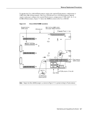
... RX CELLS RX ALARM WARNING AVOID EXPOSUREÐINVISIBLE LASER RADIATION IS EMITTED FROM THESE APERTURES. 1300 NM CLASS 1 LASER PRODUCT LASERKLASSE 1 CISCO SYSTEMS, INC. 170 W. or multi-mode SONET connections, connect the fiber cable to be dropped. Preparing for Installation 2-35 Remove the... plug by pulling on the module front panel. ATM Cabling For single- Therefore the Cisco 4500-M and Cisco 4700 routers currently support one ATM module. TASMAN DRIVE SAN JOSE CA. 95134 DATE: ÒComplies with FDA Radiation Performance Standards, ...
... RX CELLS RX ALARM WARNING AVOID EXPOSUREÐINVISIBLE LASER RADIATION IS EMITTED FROM THESE APERTURES. 1300 NM CLASS 1 LASER PRODUCT LASERKLASSE 1 CISCO SYSTEMS, INC. 170 W. or multi-mode SONET connections, connect the fiber cable to be dropped. Preparing for Installation 2-35 Remove the... plug by pulling on the module front panel. ATM Cabling For single- Therefore the Cisco 4500-M and Cisco 4700 routers currently support one ATM module. TASMAN DRIVE SAN JOSE CA. 95134 DATE: ÒComplies with FDA Radiation Performance Standards, ...

Hardware Maintenance Manual
Page 100
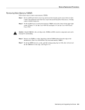
...memory configuration of 4 MB (one 4-MB SIMM) with one 8, 16, or 32-MB SIMM. The Cisco 4500-M and Cisco 4700 shared memory upgrade permits you remove or replace SIMMs. The Cisco 4000-M main memory upgrade requires replacing the main memory configuration of 16 MB (two 8-MB SIMMs) with...Female module connector on the motherboard Memory Replacement Procedures There are two dynamic random-access memory (DRAM) systems in Cisco 4000 series routers. the Cisco 4500-M and Cisco 4700 have Flash memory for the system software image and for storing the system software image; Caution To avoid damaging...
...memory configuration of 4 MB (one 4-MB SIMM) with one 8, 16, or 32-MB SIMM. The Cisco 4500-M and Cisco 4700 shared memory upgrade permits you remove or replace SIMMs. The Cisco 4000-M main memory upgrade requires replacing the main memory configuration of 16 MB (two 8-MB SIMMs) with...Female module connector on the motherboard Memory Replacement Procedures There are two dynamic random-access memory (DRAM) systems in Cisco 4000 series routers. the Cisco 4500-M and Cisco 4700 have Flash memory for the system software image and for storing the system software image; Caution To avoid damaging...
Hardware Maintenance Manual
Page 101
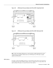
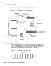
... to permit writing to the standard Flash memory configuration of 4 MB with 8, 16, 32, or 64 MB of Flash memory. Figure 5-5 Cisco 4000-M SIMM Locations Shared-memory SIMM socket Motherboard Main memory SIMM socket with proper SIMM orientation Chassis Front U3 J1 U44 J7 J8 Pin 1...SIMM sockets H2403 Boot ROM jumpers (J7 and J8) Boot ROMs Note Jumper the Boot ROM jumpers as shown in the Cisco 4000-M. The Cisco 4500-M and Cisco 4700 Flash memory upgrade requires replacing or adding to Flash memory. Maintaining and Upgrading the Router 5-7 Memory Replacement Procedures To ...
... to permit writing to the standard Flash memory configuration of 4 MB with 8, 16, 32, or 64 MB of Flash memory. Figure 5-5 Cisco 4000-M SIMM Locations Shared-memory SIMM socket Motherboard Main memory SIMM socket with proper SIMM orientation Chassis Front U3 J1 U44 J7 J8 Pin 1...SIMM sockets H2403 Boot ROM jumpers (J7 and J8) Boot ROMs Note Jumper the Boot ROM jumpers as shown in the Cisco 4000-M. The Cisco 4500-M and Cisco 4700 Flash memory upgrade requires replacing or adding to Flash memory. Maintaining and Upgrading the Router 5-7 Memory Replacement Procedures To ...
Hardware Maintenance Manual
Page 102
... Series Main Memory SIMM Alignment holes H2407 Connector edge 5-8 Cisco 4000 Series Hardware Installation and Maintenance Polarization notch Figure 5-7 shows the polarization notch and locations of Figure 5-5 and Figure 5-6. The main memory... the upper right of the alignment holes on a main memory SIMM card. Memory Replacement Procedures Figure 5-6 shows the Cisco 4500-M and Cisco 4700 SIMM and jumper locations. Figure 5-6 Cisco 4500-M and Cisco 4700 SIMM Locations Shared-memory SIMM and socket Motherboard Main memory SIMM sockets with the connector edge down and the component...
... Series Main Memory SIMM Alignment holes H2407 Connector edge 5-8 Cisco 4000 Series Hardware Installation and Maintenance Polarization notch Figure 5-7 shows the polarization notch and locations of Figure 5-5 and Figure 5-6. The main memory... the upper right of the alignment holes on a main memory SIMM card. Memory Replacement Procedures Figure 5-6 shows the Cisco 4500-M and Cisco 4700 SIMM and jumper locations. Figure 5-6 Cisco 4500-M and Cisco 4700 SIMM Locations Shared-memory SIMM and socket Motherboard Main memory SIMM sockets with the connector edge down and the component...
Hardware Maintenance Manual
Page 103
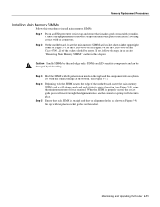
... the Router 5-9 Caution Handle SIMMs by mishandling. Step 3 Remove one SIMM at a time, beginning with the SIMM farthest from the edge of the motherboard. (The Cisco 4000-M has only one main memory SIMM.) Step 4 To lift the SIMM out of its socket, pull the locking spring clips on an ESD-preventive... end of the wrist strap to remove main memory SIMMs: Step 1 Put on both sides outward and tilt the SIMM free of Figure 5-5 (for the Cisco 4000-M) and Figure 5-6 (for the Cisco 4500-M and Cisco 4700).
... the Router 5-9 Caution Handle SIMMs by mishandling. Step 3 Remove one SIMM at a time, beginning with the SIMM farthest from the edge of the motherboard. (The Cisco 4000-M has only one main memory SIMM.) Step 4 To lift the SIMM out of its socket, pull the locking spring clips on an ESD-preventive... end of the wrist strap to remove main memory SIMMs: Step 1 Put on both sides outward and tilt the SIMM free of Figure 5-5 (for the Cisco 4000-M) and Figure 5-6 (for the Cisco 4500-M and Cisco 4700).
Hardware Maintenance Manual
Page 105
... steps in the section "Removing Main Memory SIMMS" earlier in this procedure to the metal back plate of force required. All of Figure 5-5 for the Cisco 4000-M and Figure 5-6 for the Cisco 4500-M and Cisco 4700.
... steps in the section "Removing Main Memory SIMMS" earlier in this procedure to the metal back plate of force required. All of Figure 5-5 for the Cisco 4000-M and Figure 5-6 for the Cisco 4500-M and Cisco 4700.
Hardware Maintenance Manual
Page 107
... pull it might damage them. Step 10 Proceed to the metal back plate of the motherboard as shown in Figure 5-5 (for the Cisco 4000-M) and Figure 5-6 (for the Cisco 4500-M and Cisco 4700). Maintaining and Upgrading the Router 5-13 Step 8 Place the removed SIMM in this chapter. The sides of the chassis is closest...
... pull it might damage them. Step 10 Proceed to the metal back plate of the motherboard as shown in Figure 5-5 (for the Cisco 4000-M) and Figure 5-6 (for the Cisco 4500-M and Cisco 4700). Maintaining and Upgrading the Router 5-13 Step 8 Place the removed SIMM in this chapter. The sides of the chassis is closest...
Hardware Maintenance Manual
Page 110
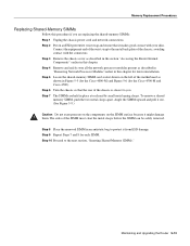
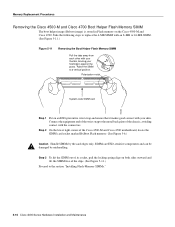
... are ESD-sensitive components and can be damaged by the card edges only. Polarization notch H2462 System-code SIMM card Step 1 Put on the Cisco 4500-M and Cisco 4700. Step 3 To lift the SIMM out of its socket, pull the locking spring clips on both sides outward and tilt the SIMM free... of the Cisco 4500-M and Cisco 4700 motherboard, locate the SIMM card socket marked RxBoot Flash memory. (See Figure 5-6.) Caution Handle SIMMs by mishandling. Raise the SIMM to replace the...
... are ESD-sensitive components and can be damaged by the card edges only. Polarization notch H2462 System-code SIMM card Step 1 Put on the Cisco 4500-M and Cisco 4700. Step 3 To lift the SIMM out of its socket, pull the locking spring clips on both sides outward and tilt the SIMM free... of the Cisco 4500-M and Cisco 4700 motherboard, locate the SIMM card socket marked RxBoot Flash memory. (See Figure 5-6.) Caution Handle SIMMs by mishandling. Raise the SIMM to replace the...
