User Guide
Page 1
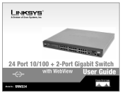
® A Division of Cisco Systems, Inc. 24 Port 10/100 + 2-Port Gigabit Switch with WebView User Guide WIRED Model No. SRW224
® A Division of Cisco Systems, Inc. 24 Port 10/100 + 2-Port Gigabit Switch with WebView User Guide WIRED Model No. SRW224
User Guide
Page 2
... checkmark means there is a note of Figures" section. Copyright © 2004 Cisco Systems, Inc. Look for technical terms that could damage your property or the Switch. How to make understanding networking with the switch easier than ever. This question mark provides you with a figure number and description.... Other brands and product names are trademarks or registered trademarks of Cisco Systems, Inc. This exclamation point means there is a caution or warning and is something you might need to while using the Switch. and/or its affiliates in the "List of interest and is...
... checkmark means there is a note of Figures" section. Copyright © 2004 Cisco Systems, Inc. Look for technical terms that could damage your property or the Switch. How to make understanding networking with the switch easier than ever. This question mark provides you with a figure number and description.... Other brands and product names are trademarks or registered trademarks of Cisco Systems, Inc. This exclamation point means there is a caution or warning and is something you might need to while using the Switch. and/or its affiliates in the "List of interest and is...
User Guide
Page 3
...this Guide? 2 Chapter 2: Getting to Know the Switch 4 The Front Panel 4 The Back Panel 5 The Side Panel 5 Chapter 3: Connecting the Switch 7 Overview 7 Pre-Installation Considerations 8 Hardware Installation 8 Placement Options 9 Uplinking the Switch 10 Chapter 4: Configuration using the Console Interface 11 ...Overview 11 Configuring the HyperTerminal Application 11 Configuring the Switch through the Console Interface 12 Chapter 5: Configuring the Switch through the Web Utility 19 Overview 19 System Tab 20 Port Tab 22 Trunk...
...this Guide? 2 Chapter 2: Getting to Know the Switch 4 The Front Panel 4 The Back Panel 5 The Side Panel 5 Chapter 3: Connecting the Switch 7 Overview 7 Pre-Installation Considerations 8 Hardware Installation 8 Placement Options 9 Uplinking the Switch 10 Chapter 4: Configuration using the Console Interface 11 ...Overview 11 Configuring the HyperTerminal Application 11 Configuring the Switch through the Console Interface 12 Chapter 5: Configuring the Switch through the Web Utility 19 Overview 19 System Tab 20 Port Tab 22 Trunk...
User Guide
Page 4
24-port 10/100 + 2-Port Gigabit Switch with WebView Appendix E: Specifications 38 Appendix F: Warranty Information 39 Appendix G: Regulatory Information 40 Appendix H: Contact Information 41
24-port 10/100 + 2-Port Gigabit Switch with WebView Appendix E: Specifications 38 Appendix F: Warranty Information 39 Appendix G: Regulatory Information 40 Appendix H: Contact Information 41
User Guide
Page 5
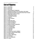
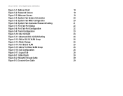
... Typical Network Configuration 7 Figure 3-2: Attaching the Rubber Feet to the Bottom of the Switch 9 Figure 3-3: Attaching the Brackets to the Switch (Front Panel Forward) 9 Figure 3-4: Mounting the Switch in A Rack 10 Figure 4-1: Finding HyperTerminal 11 Figure 4-2: Connection Description 11 Figure ...To 11 Figure 4-4: COM1 Properties 12 Figure 4-5: Login 12 Figure 4-6: Switch Main Menu 12 Figure 4-7: System Configuration 13 Figure 4-8: System Information 13 Figure 4-9: Advanced Switch Configuration 14 Figure 4-10: Password Setting 14 Figure 4-11: IP Configuration ...
... Typical Network Configuration 7 Figure 3-2: Attaching the Rubber Feet to the Bottom of the Switch 9 Figure 3-3: Attaching the Brackets to the Switch (Front Panel Forward) 9 Figure 3-4: Mounting the Switch in A Rack 10 Figure 4-1: Finding HyperTerminal 11 Figure 4-2: Connection Description 11 Figure ...To 11 Figure 4-4: COM1 Properties 12 Figure 4-5: Login 12 Figure 4-6: Switch Main Menu 12 Figure 4-7: System Configuration 13 Figure 4-8: System Information 13 Figure 4-9: Advanced Switch Configuration 14 Figure 4-10: Password Setting 14 Figure 4-11: IP Configuration ...
User Guide
Page 6
24-port 10/100 + 2-Port Gigabit Switch with WebView Figure 5-1: Addrees Field 19 Figure 5-2: Password Screen 19 Figure 5-3: Welcome Screen 19 Figure 5-4: System Tab-System Information 20 Figure 5-5: System Tab-MISC Configuration ...
24-port 10/100 + 2-Port Gigabit Switch with WebView Figure 5-1: Addrees Field 19 Figure 5-2: Password Screen 19 Figure 5-3: Welcome Screen 19 Figure 5-4: System Tab-System Information 20 Figure 5-5: System Tab-MISC Configuration ...
User Guide
Page 7
... network backbone. Each port independently and automatically negotiates for best speed and whether to run in this User Guide to help you connect the Switch, set it up, and configure it easy to manage the 26 VLANs and up your web browser, making it to bridge your network ...can use the integrated console port to configure the switch. These instructions should be all you need to 7 trunking groups. It features WebView monitoring and configuration via your workstations, while the two integrated...
... network backbone. Each port independently and automatically negotiates for best speed and whether to run in this User Guide to help you connect the Switch, set it up, and configure it easy to manage the 26 VLANs and up your web browser, making it to bridge your network ...can use the integrated console port to configure the switch. These instructions should be all you need to 7 trunking groups. It features WebView monitoring and configuration via your workstations, while the two integrated...
User Guide
Page 8
... up and using the Console Interface This chapter instructs you on how to use the Switch's console interface for configuring the Switch. • Chapter 5: Configuring the Switch through the Web Utility This chapter shows you how to configure the Switch usign the Web Utility. • Appendix A: Fast Ethernet and Gigabit Ethernet This appendix describes...
... up and using the Console Interface This chapter instructs you on how to use the Switch's console interface for configuring the Switch. • Chapter 5: Configuring the Switch through the Web Utility This chapter shows you how to configure the Switch usign the Web Utility. • Appendix A: Fast Ethernet and Gigabit Ethernet This appendix describes...

User Guide
Page 9
Chapter 1: Introduction 3 What's in this Guide? 24-port 10/100 + 2-Port Gigabit Switch with WebView • Appendix H: Contact Information This appendix provides contact information for a variety of Linksys resources, including Technical Support.
Chapter 1: Introduction 3 What's in this Guide? 24-port 10/100 + 2-Port Gigabit Switch with WebView • Appendix H: Contact Information This appendix provides contact information for a variety of Linksys resources, including Technical Support.
User Guide
Page 10
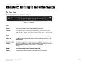
.../ACT Green. Chapter 2: Getting to 1000Mbps. Figure 2-1: Front Panel LEDs System Green. Blinks to indicate that the Switch is actively sending or receiving data over that is being supplied to the Switch. They link to high-speed network peripheral system or clients at speeds of up to Know the...(Local Area Network) ports connect to indicate the port is where you connect a serial cable from a PC's serial port. Lights to Know the Switch The Front Panel The Switch's LEDs and ports are located on the front panel. Gigabit Green. Lights to Ethernet network devices, such as other...
.../ACT Green. Chapter 2: Getting to 1000Mbps. Figure 2-1: Front Panel LEDs System Green. Blinks to indicate that the Switch is actively sending or receiving data over that is being supplied to the Switch. They link to high-speed network peripheral system or clients at speeds of up to Know the...(Local Area Network) ports connect to indicate the port is where you connect a serial cable from a PC's serial port. Lights to Know the Switch The Front Panel The Switch's LEDs and ports are located on the front panel. Gigabit Green. Lights to Ethernet network devices, such as other...
User Guide
Page 11
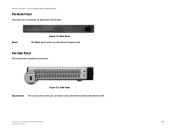
Power Figure 2-2: Back Panel The Power port is where you can attach a lock so the Switch will connect the power cord. Figure 2-3: Side Panel Security Slot The security slot is where you will be protected from theft. Chapter 2: Getting to Know the Switch 5 The Back Panel 24-port 10/100 + 2-Port Gigabit Switch with WebView The Back Panel The power port is located on a side panel. The Side Panel The security slot is located on the back panel of the Switch.
Power Figure 2-2: Back Panel The Power port is where you can attach a lock so the Switch will connect the power cord. Figure 2-3: Side Panel Security Slot The security slot is where you will be protected from theft. Chapter 2: Getting to Know the Switch 5 The Back Panel 24-port 10/100 + 2-Port Gigabit Switch with WebView The Back Panel The power port is located on a side panel. The Side Panel The security slot is located on the back panel of the Switch.

User Guide
Page 12
... provide links to install an MGBT1, MGBSX2, or MGBLH1 Gigabit expansion module and use a network cable. Go to manage the Switch using the provided serial cable. You will need to high-speed network segments or individual workstations at www.linksys.com for configuration purposes...one expansion module. With this and many other Linksys products, your networking options are limitless. The Console Port The Switch is equipped with the Switch. Chapter 2: Getting to the Twisted-Pair Cabling section. For more information about products that allows you to connect to...
... provide links to install an MGBT1, MGBSX2, or MGBLH1 Gigabit expansion module and use a network cable. Go to manage the Switch using the provided serial cable. You will need to high-speed network segments or individual workstations at www.linksys.com for configuration purposes...one expansion module. With this and many other Linksys products, your networking options are limitless. The Console Port The Switch is equipped with the Switch. Chapter 2: Getting to the Twisted-Pair Cabling section. For more information about products that allows you to connect to...
User Guide
Page 13
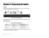
... devices, make sure you don't exceed the maximum cabling distances, which are listed in Figure 3-1. Table 1: Maximum Cabling Distances From Switch Hub Switch or Hub To Switch or Hub Hub Computer Maximum Distance 100 meters (328 feet) 5 meters (16,4 feet) 100 meters (328 feet) *A hub ...configuration, see the application diagram shown in the following table: Maximum Cabling Distances. 24-port 10/100 + 2-Port Gigabit Switch with WebView Chapter 3: Connecting the Switch Overview This chapter will explain how to connect network devices to 100 meters (328 feet) Chapter 3: Connecting the...
... devices, make sure you don't exceed the maximum cabling distances, which are listed in Figure 3-1. Table 1: Maximum Cabling Distances From Switch Hub Switch or Hub To Switch or Hub Hub Computer Maximum Distance 100 meters (328 feet) 5 meters (16,4 feet) 100 meters (328 feet) *A hub ...configuration, see the application diagram shown in the following table: Maximum Cabling Distances. 24-port 10/100 + 2-Port Gigabit Switch with WebView Chapter 3: Connecting the Switch Overview This chapter will explain how to connect network devices to 100 meters (328 feet) Chapter 3: Connecting the...
User Guide
Page 14
...8226; Connect Network Devices Hardware Installation To connect network devices to the Switch are powered off. 2. Chapter 3: Connecting the Switch 8 Pre-Installation Considerations 24-port 10/100 + 2-Port Gigabit Switch with WebView Pre-Installation Considerations Fast Ethernet Considerations If you will be...using Category 5 cable is accessible and that the switch is 328 feet (100 meters). If you choose a location for the Switch, observe the following guidelines: Full-Duplex Considerations As previously mentioned, the Switch provides full-duplex support for Fast Ethernet (100Mbps...
...8226; Connect Network Devices Hardware Installation To connect network devices to the Switch are powered off. 2. Chapter 3: Connecting the Switch 8 Pre-Installation Considerations 24-port 10/100 + 2-Port Gigabit Switch with WebView Pre-Installation Considerations Fast Ethernet Considerations If you will be...using Category 5 cable is accessible and that the switch is 328 feet (100 meters). If you choose a location for the Switch, observe the following guidelines: Full-Duplex Considerations As previously mentioned, the Switch provides full-duplex support for Fast Ethernet (100Mbps...
User Guide
Page 15
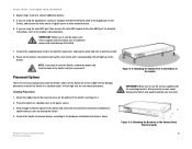
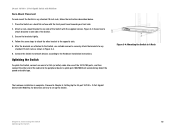
...Attach the rubber feet to use the power cord that is supplied with WebView 4. Place the Switch on the devices connected to the Bottom of the Switch and then reconnect it. Connect the Switch to network devices according to connect additional devices. 5. Power on a desktop near an AC ... port, connect a Category 5e Ethernet network cable to physically install the Switch, either set the Switch on the bottom of a different power cord could damage the Switch and would invalidate your warranty. 1. Use of the Switch. Connect the supplied power cord to a Gigabit server or other end...
...Attach the rubber feet to use the power cord that is supplied with WebView 4. Place the Switch on the devices connected to the Bottom of the Switch and then reconnect it. Connect the Switch to network devices according to connect additional devices. 5. Power on a desktop near an AC ... port, connect a Category 5e Ethernet network cable to physically install the Switch, either set the Switch on the bottom of a different power cord could damage the Switch and would invalidate your warranty. 1. Use of the Switch. Connect the supplied power cord to a Gigabit server or other end...
User Guide
Page 16
...Secure the brackets tightly. 4. MDI/MDIX will automaticlaly detect the speed and cable type. Figure 3-4: Mounting the Switch in any standard 19-inch rack as shown in Figure 3-3. 6. Connect the Switch to network devices according to any standard 19-inch rack, follow the instructions described below. 1. Proceed to .... Figure 3-2 shows how to attach brackets to the opposite side. 5. Attach a rack-mount bracket to attach the other end of the Switch with the supplied screws. Follow the same steps to one side of the cable into one side of the 24 10/100 ports, and then...
...Secure the brackets tightly. 4. MDI/MDIX will automaticlaly detect the speed and cable type. Figure 3-4: Mounting the Switch in any standard 19-inch rack as shown in Figure 3-3. 6. Connect the Switch to network devices according to any standard 19-inch rack, follow the instructions described below. 1. Proceed to .... Figure 3-2 shows how to attach brackets to the opposite side. 5. Attach a rack-mount bracket to attach the other end of the Switch with the supplied screws. Follow the same steps to one side of the cable into one side of the 24 10/100 ports, and then...
User Guide
Page 17
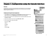
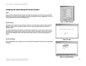
...: None Stop bits: 1 Flow control: None Figure 4-1: Finding HyperTerminal Figure 4-2: Connection Description Chapter 4: Configuration using the Console Interface Overview The Switch features a menu-driven console interface for basic switch configuration. Select HyperTerminal. Enter a name for the application. Configuring the HyperTerminal Application 1. Click OK. 3. Select a port to configure the HyperTerminal... Communications. HyperTerminal should be one of connection is SRW224. Running the Hyper Terminal utility program. 2. 24-port 10/100 + 2-Port Gigabit Switch with the...
...: None Stop bits: 1 Flow control: None Figure 4-1: Finding HyperTerminal Figure 4-2: Connection Description Chapter 4: Configuration using the Console Interface Overview The Switch features a menu-driven console interface for basic switch configuration. Select HyperTerminal. Enter a name for the application. Configuring the HyperTerminal Application 1. Click OK. 3. Select a port to configure the HyperTerminal... Communications. HyperTerminal should be one of connection is SRW224. Running the Hyper Terminal utility program. 2. 24-port 10/100 + 2-Port Gigabit Switch with the...
User Guide
Page 18
... listing of menus. Figure 4-4: COM1 Properties Figure 4-5: Login Chapter 4: Configuration using the Console Interface Configuring the Switch through the Console Interface Figure 4-6: Switch Main Menu 12 pressing the Enter key activates the highlighted option. menu options and any values entered or present ... You can set a new password later from the Password Setting screen. 24-port 10/100 + 2-Port Gigabit Switch with WebView Configuring the Switch through the Console Interface Login When you finish configuring the Hyper Terminal, the Login screen will get highlighted. A highlight...
... listing of menus. Figure 4-4: COM1 Properties Figure 4-5: Login Chapter 4: Configuration using the Console Interface Configuring the Switch through the Console Interface Figure 4-6: Switch Main Menu 12 pressing the Enter key activates the highlighted option. menu options and any values entered or present ... You can set a new password later from the Password Setting screen. 24-port 10/100 + 2-Port Gigabit Switch with WebView Configuring the Switch through the Console Interface Login When you finish configuring the Hyper Terminal, the Login screen will get highlighted. A highlight...
User Guide
Page 19
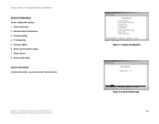
System Information In System Information, you can check the Firmware Version. Advanced Switch Configuration 3. Firmware Update 6. Return to Main Menu. IP Configuration 5. Chapter 4: Configuration using the Console Interface Configuring the Switch through the Console Interface Figure 4-7: System Configuration Figure 4-8: System Information 13 24-port 10/100 + 2-Port Gigabit Switch with WebView System Configuration System Configuration displays: 1. Password Setting 4. Restore System Default Setting 7. Reboot System 0. System Information 2.
System Information In System Information, you can check the Firmware Version. Advanced Switch Configuration 3. Firmware Update 6. Return to Main Menu. IP Configuration 5. Chapter 4: Configuration using the Console Interface Configuring the Switch through the Console Interface Figure 4-7: System Configuration Figure 4-8: System Information 13 24-port 10/100 + 2-Port Gigabit Switch with WebView System Configuration System Configuration displays: 1. Password Setting 4. Restore System Default Setting 7. Reboot System 0. System Information 2.
User Guide
Page 20
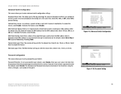
...filter by percentage the amount of broadcast traffic to prevent a storm of six characters, using the Console Interface 14 Configuring the Switch through 9. Broadcast Storm Filter. Select 5%, 10%, or 20%. Collision Retry Forever. To disable this feature, select Enable. ...after the chosen time. Password Protection. This allows you don't want to have a password to disable the feature. Figure 4-9: Advanced Switch Configuration Figure 4-10: Password Setting Chapter 4: Configuration using the letters a through z, and numbers 0 through the Console Interface To ...
...filter by percentage the amount of broadcast traffic to prevent a storm of six characters, using the Console Interface 14 Configuring the Switch through 9. Broadcast Storm Filter. Select 5%, 10%, or 20%. Collision Retry Forever. To disable this feature, select Enable. ...after the chosen time. Password Protection. This allows you don't want to have a password to disable the feature. Figure 4-9: Advanced Switch Configuration Figure 4-10: Password Setting Chapter 4: Configuration using the letters a through z, and numbers 0 through the Console Interface To ...


