
Installation Guide
Page 3
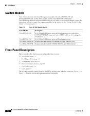
...-Panel Description 1-2 10/100 Ports 1-5 Dual-Purpose Ports 1-5 100BASE-FX Ports 1-5 Power and Relay Connector 1-5 Console Port 1-6 LEDs 1-6 Setup LED 1-8 System LED 1-9 Alarm LED 1-9 Power Status LED 1-9 10/100 Port Status LEDs 1-10 100Base-FX Port Status LEDs 1-...10 Dual-Purpose Port LEDs 1-11 Compact Flash Memory Card 1-11 Rear-Panel Description 1-12 Power Converter (Optional) 1-13 Management Options 1-14 Network Configurations 1-15 Switch Installation 2-1 Preparing for Installation 2-1 Warnings 2-2 Cisco IE 3000...
...-Panel Description 1-2 10/100 Ports 1-5 Dual-Purpose Ports 1-5 100BASE-FX Ports 1-5 Power and Relay Connector 1-5 Console Port 1-6 LEDs 1-6 Setup LED 1-8 System LED 1-9 Alarm LED 1-9 Power Status LED 1-9 10/100 Port Status LEDs 1-10 100Base-FX Port Status LEDs 1-...10 Dual-Purpose Port LEDs 1-11 Compact Flash Memory Card 1-11 Rear-Panel Description 1-12 Power Converter (Optional) 1-13 Management Options 1-14 Network Configurations 1-15 Switch Installation 2-1 Preparing for Installation 2-1 Warnings 2-2 Cisco IE 3000...
Installation Guide
Page 4
...Installing the Switch in a Rack 2-29 Removing the Switch from a DIN Rail or a Rack 2-31 Connecting Power and Alarm Circuits 2-32 Wiring the Protective Ground and DC Power 2-32 Wiring the External Alarms 2-33 Connecting Destination Ports 2-36 Connecting to 10/100 and 10/100/1000 ... Connecting the Switch to the Power Converter 2-44 Attaching the Power Converter to the Switch 2-45 Installing the Power Converter on a DIN Rail, Wall, or Rack Adapter 2-46 Connecting the DC Power Clip 2-46 Connecting the Power Converter to an AC Power Source 2-47 Cisco IE 3000 Switch Hardware Installation Guide iv OL...
...Installing the Switch in a Rack 2-29 Removing the Switch from a DIN Rail or a Rack 2-31 Connecting Power and Alarm Circuits 2-32 Wiring the Protective Ground and DC Power 2-32 Wiring the External Alarms 2-33 Connecting Destination Ports 2-36 Connecting to 10/100 and 10/100/1000 ... Connecting the Switch to the Power Converter 2-44 Attaching the Power Converter to the Switch 2-45 Installing the Power Converter on a DIN Rail, Wall, or Rack Adapter 2-46 Connecting the DC Power Clip 2-46 Connecting the Power Converter to an AC Power Source 2-47 Cisco IE 3000 Switch Hardware Installation Guide iv OL...
Installation Guide
Page 5
... E R A A P P E N D I X B A P P E N D I X OL-13017-01 Preparing the AC Power Cord 2-47 Connecting the AC Power Cord to the Power Converter 2-48 Connecting the Power Converter to a DC Power Source 2-51 Applying Power to the Power Converter 2-53 Where to Go Next 2-53 Troubleshooting 3-1 Diagnosing Problems 3-1 Verify Switch POST Results 3-1 Verify Switch LEDs 3-2 Verify Switch Connections 3-2 ... Installation Guidelines B-5 Environment and Enclosure Guidelines: B-5 Other Guidelines B-6 Verifying Package Contents B-7 Adding Modules to the Switch B-8 Cisco IE 3000 Switch Hardware Installation Guide v
... E R A A P P E N D I X B A P P E N D I X OL-13017-01 Preparing the AC Power Cord 2-47 Connecting the AC Power Cord to the Power Converter 2-48 Connecting the Power Converter to a DC Power Source 2-51 Applying Power to the Power Converter 2-53 Where to Go Next 2-53 Troubleshooting 3-1 Diagnosing Problems 3-1 Verify Switch POST Results 3-1 Verify Switch LEDs 3-2 Verify Switch Connections 3-2 ... Installation Guidelines B-5 Environment and Enclosure Guidelines: B-5 Other Guidelines B-6 Verifying Package Contents B-7 Adding Modules to the Switch B-8 Cisco IE 3000 Switch Hardware Installation Guide v
Installation Guide
Page 6
..., or Rack Adapter B-52 Connecting the DC Power Clip B-52 Connecting the Power Converter to an AC Power Source B-53 Preparing the AC Power Cord B-53 Connecting the AC Power Cord to the Power Converter B-54 Connecting the Power Converter to a DC Power Source B-57 Applying Power to the Power Converter B-59 Cisco IE 3000 Switch Hardware Installation Guide vi OL-13017-01
..., or Rack Adapter B-52 Connecting the DC Power Clip B-52 Connecting the Power Converter to an AC Power Source B-53 Preparing the AC Power Cord B-53 Connecting the AC Power Cord to the Power Converter B-54 Connecting the Power Converter to a DC Power Source B-57 Applying Power to the Power Converter B-59 Cisco IE 3000 Switch Hardware Installation Guide vi OL-13017-01

Installation Guide
Page 11
... page 1-11 • Rear-Panel Description, page 1-12 • Power Converter (Optional), page 1-13 • Management Options, page 1-14 • Network Configurations, page 1-15 Overview The Cisco IE 3000 switch provides a rugged and secure switching infrastructure for industrial Ethernet applications, ... (PLCs), human-machine interfaces (HMIs), drives, sensors, traffic signal controllers, and intelligent electronic devices (IEDs). OL-13017-01 Cisco IE 3000 Switch Hardware Installation Guide 1-1 Overview 1 C H A P T E R This chapter provides these topics that are designed to withstand...
... page 1-11 • Rear-Panel Description, page 1-12 • Power Converter (Optional), page 1-13 • Management Options, page 1-14 • Network Configurations, page 1-15 Overview The Cisco IE 3000 switch provides a rugged and secure switching infrastructure for industrial Ethernet applications, ... (PLCs), human-machine interfaces (HMIs), drives, sensors, traffic signal controllers, and intelligent electronic devices (IEDs). OL-13017-01 Cisco IE 3000 Switch Hardware Installation Guide 1-1 Overview 1 C H A P T E R This chapter provides these topics that are designed to withstand...
Installation Guide
Page 12
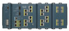
...power and relay connectors. Figure 1-1 to the Switch" section on how to connect the expansion modules to the switch, see the "Adding Modules to Figure 1-4 show the switch and expansion module front panels. For instructions on page 2-5. . The Cisco IE-3000-4TC and the Cisco IE-3000-8TC are the switch models, and the Cisco IEM-3000-8TM and the Cisco... IEM-3000-8FM are expansion modules that you can connect to increase...
...power and relay connectors. Figure 1-1 to the Switch" section on how to connect the expansion modules to the switch, see the "Adding Modules to Figure 1-4 show the switch and expansion module front panels. For instructions on page 2-5. . The Cisco IE-3000-4TC and the Cisco IE-3000-8TC are the switch models, and the Cisco IEM-3000-8TM and the Cisco... IEM-3000-8FM are expansion modules that you can connect to increase...
Installation Guide
Page 13
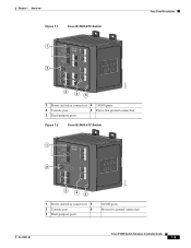
Chapter 1 Overview Figure 1-1 Cisco IE-3000-8TC Switch 1 2 Front-Panel Description 201699 3 45 1 Power and relay connectors 4 10/100 ports 2 Console port 5 Protective ground connection 3 Dual-purpose ports Figure 1-2 Cisco IE-3000-4TC Switch 1 2 201700 3 45 1 Power and relay connectors 4 2 Console port 5 3 Dual-purpose ports 10/100 ports Protective ground connection OL-13017-01 Cisco IE 3000 Switch Hardware Installation Guide 1-3
Chapter 1 Overview Figure 1-1 Cisco IE-3000-8TC Switch 1 2 Front-Panel Description 201699 3 45 1 Power and relay connectors 4 10/100 ports 2 Console port 5 Protective ground connection 3 Dual-purpose ports Figure 1-2 Cisco IE-3000-4TC Switch 1 2 201700 3 45 1 Power and relay connectors 4 2 Console port 5 3 Dual-purpose ports 10/100 ports Protective ground connection OL-13017-01 Cisco IE 3000 Switch Hardware Installation Guide 1-3
Installation Guide
Page 15
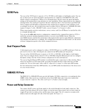
...interfaces when inserted in an SFP module slot. One connector provides primary DC power (supply A) and the major alarm signal, and a second connector (supply B) provides secondary power and the minor alarm signal. OL-13017-01 Cisco IE 3000 Switch Hardware Installation Guide 1-5 In all cases, the attached device must be... cable. 10BASE-T traffic can use the mdix auto interface configuration command in the command-line interface (CLI) to workstations, servers, routers, and Cisco IP Phones, be active at 10, 100, or 1000 Mb/s in full-duplex or half-duplex mode. The cable can be up to ...
...interfaces when inserted in an SFP module slot. One connector provides primary DC power (supply A) and the major alarm signal, and a second connector (supply B) provides secondary power and the minor alarm signal. OL-13017-01 Cisco IE 3000 Switch Hardware Installation Guide 1-5 In all cases, the attached device must be... cable. 10BASE-T traffic can use the mdix auto interface configuration command in the command-line interface (CLI) to workstations, servers, routers, and Cisco IP Phones, be active at 10, 100, or 1000 Mb/s in full-duplex or half-duplex mode. The cable can be up to ...
Installation Guide
Page 16
... to monitor individual switches and switch clusters. When both alarm relays. Cisco IE 3000 Switch Hardware Installation Guide 1-6 OL-13017-01 If one or with one of the two power sources fail, the other continues to indicate an alarm with dual power sources. The power and relay connectors also provide an interface for two independent alarm...
... to monitor individual switches and switch clusters. When both alarm relays. Cisco IE 3000 Switch Hardware Installation Guide 1-6 OL-13017-01 If one or with one of the two power sources fail, the other continues to indicate an alarm with dual power sources. The power and relay connectors also provide an interface for two independent alarm...
Installation Guide
Page 19
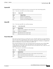
... circuit. Alarm LED Table 1-4 lists the alarm LED colors and their meanings. If power is green. If the switch has dual power sources, the switch draws power from the power source with one of the corresponding DC input. OL-13017-01 Cisco IE 3000 Switch Hardware Installation Guide 1-9 Table 1-3 lists the system LED colors and their meanings...
... circuit. Alarm LED Table 1-4 lists the alarm LED colors and their meanings. If power is green. If the switch has dual power sources, the switch draws power from the power source with one of the corresponding DC input. OL-13017-01 Cisco IE 3000 Switch Hardware Installation Guide 1-9 Table 1-3 lists the system LED colors and their meanings...
Installation Guide
Page 20
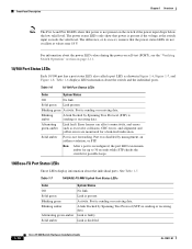
...while STP checks the switch for a link-fault indication. Link is disabled. 1-10 Cisco IE 3000 Switch Hardware Installation Guide OL-13017-01 Link is faulty. The power status LEDs only show that power is reconfigured, the port LED can affect connectivity, and errors such as shown in Figure... or receiving data. Front-Panel Description Chapter 1 Overview Note The Pwr A and Pwr B LEDs show that power is present. The difference, or hysteresis, ensures that the power status LEDs do not oscillate at the switch input exceeds the valid level. Solid green Link present. Activity.
...while STP checks the switch for a link-fault indication. Link is disabled. 1-10 Cisco IE 3000 Switch Hardware Installation Guide OL-13017-01 Link is faulty. The power status LEDs only show that power is reconfigured, the port LED can affect connectivity, and errors such as shown in Figure... or receiving data. Front-Panel Description Chapter 1 Overview Note The Pwr A and Pwr B LEDs show that power is present. The difference, or hysteresis, ensures that the power status LEDs do not oscillate at the switch input exceeds the valid level. Solid green Link present. Activity.
Installation Guide
Page 22
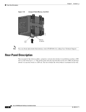
... a wall. Rear-Panel Description Figure 1-10 Compact Flash Memory Card Slot Chapter 1 Overview 201832 Bottom 1 of the switch, modules, and power converter have latches for installation on the wall. 1-12 Cisco IE 3000 Switch Hardware Installation Guide OL-13017-01 Rear-Panel Description The rear panel of switch Note You can obtain replacement flash...
... a wall. Rear-Panel Description Figure 1-10 Compact Flash Memory Card Slot Chapter 1 Overview 201832 Bottom 1 of the switch, modules, and power converter have latches for installation on the wall. 1-12 Cisco IE 3000 Switch Hardware Installation Guide OL-13017-01 Rear-Panel Description The rear panel of switch Note You can obtain replacement flash...

Installation Guide
Page 23
..., see the "Connecting the Switch to the switch through a preassembled power cable. The power converter (PWR-IE3000-AC) can supply 24-VDC power to one switch and up to two modules. OL-13017-01 Cisco IE 3000 Switch Hardware Installation Guide 1-13 Note The power converter (PWR-IE3000-AC=) is mounted on the side of a switch and...
..., see the "Connecting the Switch to the switch through a preassembled power cable. The power converter (PWR-IE3000-AC) can supply 24-VDC power to one switch and up to two modules. OL-13017-01 Cisco IE 3000 Switch Hardware Installation Guide 1-13 Note The power converter (PWR-IE3000-AC=) is mounted on the side of a switch and...
Installation Guide
Page 24
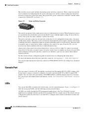
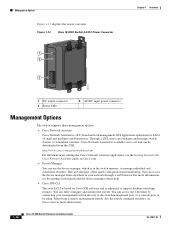
... standalone switches. Management Options Figure 1-12 displays the power converter. Figure 1-12 Cisco IE 3000 Switch AC/DC Power Converter 1 2 3 Chapter 1 Overview 202314 1 DC output connector 2 Status LED 3 AC/DC input power connector Management Options The switch supports these management options: • Cisco Network Assistant Cisco Network Assistant is based on Cisco.com. • Device Manager You can access...
... standalone switches. Management Options Figure 1-12 displays the power converter. Figure 1-12 Cisco IE 3000 Switch AC/DC Power Converter 1 2 3 Chapter 1 Overview 202314 1 DC output connector 2 Status LED 3 AC/DC input power connector Management Options The switch supports these management options: • Cisco Network Assistant Cisco Network Assistant is based on Cisco.com. • Device Manager You can access...

Installation Guide
Page 27
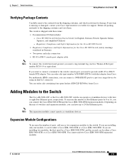
Read these topics: • Warnings, page 2-2 • Installation Guidelines, page 2-3 • Verifying Package Contents, page 2-5 OL-13017-01 Cisco IE 3000 Switch Hardware Installation Guide 2-1 Switch Installation 2 C H A P T E R This chapter describes how to install your installation is in a hazardous ... Operation, page 2-11 • Installing the Switch, page 2-23 • Connecting Power and Alarm Circuits, page 2-32 • Connecting Destination Ports, page 2-36 • Connecting the Switch to the Power Converter, page 2-44 • Where to Go Next, page 2-53 Preparing for ...
Read these topics: • Warnings, page 2-2 • Installation Guidelines, page 2-3 • Verifying Package Contents, page 2-5 OL-13017-01 Cisco IE 3000 Switch Hardware Installation Guide 2-1 Switch Installation 2 C H A P T E R This chapter describes how to install your installation is in a hazardous ... Operation, page 2-11 • Installing the Switch, page 2-23 • Connecting Power and Alarm Circuits, page 2-32 • Connecting Destination Ports, page 2-36 • Connecting the Switch to the Power Converter, page 2-44 • Where to Go Next, page 2-53 Preparing for ...
Installation Guide
Page 28
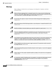
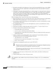
...activity. Metal objects will heat up when connected to power and ground and can be accessed only through an approved network termination unit with integral circuit protection. 10/100/1000 Ethernet Statement 1044 Cisco IE 3000 Switch Hardware Installation Guide 2-2 OL-13017-01 A restricted... that is intended for Installation Chapter 2 Switch Installation Warnings These warnings are uncertain that power is available. Statement 1004 Warning This unit is connected to its power source. Never defeat the ground conductor or operate the equipment in the absence of security...
...activity. Metal objects will heat up when connected to power and ground and can be accessed only through an approved network termination unit with integral circuit protection. 10/100/1000 Ethernet Statement 1044 Cisco IE 3000 Switch Hardware Installation Guide 2-2 OL-13017-01 A restricted... that is intended for Installation Chapter 2 Switch Installation Warnings These warnings are uncertain that power is available. Statement 1004 Warning This unit is connected to its power source. Never defeat the ground conductor or operate the equipment in the absence of security...
Installation Guide
Page 30
... in improper or intermittent grounding. Front: 2.56 in . (105 mm) - Front-panel direct current (DC) power and relay connector is within the ranges listed in Appendix A, "Technical Specifications." • Clearance to the mounting surface...power source. • Airflow around the switch and through the DIN rail to the module): 3.54 in Class I, Division 2, Groups A, B, C, D, or nonhazardous locations. The temperature inside the enclosure cannot exceed 140°F (60°C), the maximum ambient enclosure temperature of the connection to ports is unrestricted. Cisco IE 3000...
... in improper or intermittent grounding. Front: 2.56 in . (105 mm) - Front-panel direct current (DC) power and relay connector is within the ranges listed in Appendix A, "Technical Specifications." • Clearance to the mounting surface...power source. • Airflow around the switch and through the DIN rail to the module): 3.54 in Class I, Division 2, Groups A, B, C, D, or nonhazardous locations. The temperature inside the enclosure cannot exceed 140°F (60°C), the maximum ambient enclosure temperature of the connection to ports is unrestricted. Cisco IE 3000...
Installation Guide
Page 31
... you are installing two modules, the first must be a Cisco IEM-3000-8TM, and the second can be either a Cisco IEM-3000-8TM or a Cisco IEM-3000-8FM. Cisco IE 3000 Switch Getting Started Guide (in German) • Two power and relay connectors • RJ-45 to DB-9 console ...ports, respectively. You can connect the Cisco IEM-3000-8TM and the Cisco IEM-3000-8FM expansion modules. Adding Modules to the Switch The Cisco IE-3000-4TC or the Cisco IE-3000-8TC switch can order a kit containing four spare latches (DINCLP-IE3000=) from Cisco. Chapter 2 Switch Installation Adding Modules to...
... you are installing two modules, the first must be a Cisco IEM-3000-8TM, and the second can be either a Cisco IEM-3000-8TM or a Cisco IEM-3000-8FM. Cisco IE 3000 Switch Getting Started Guide (in German) • Two power and relay connectors • RJ-45 to DB-9 console ...ports, respectively. You can connect the Cisco IEM-3000-8TM and the Cisco IEM-3000-8FM expansion modules. Adding Modules to the Switch The Cisco IE-3000-4TC or the Cisco IE-3000-8TC switch can order a kit containing four spare latches (DINCLP-IE3000=) from Cisco. Chapter 2 Switch Installation Adding Modules to...

Installation Guide
Page 37
See Figure 2-7. These sections describe the steps required to connect a PC or terminal to the switch console port, to power on the switch, and to observe POST results: • Connecting a PC or a Terminal to remove or replace the compact flash memory card: Step 1 Locate ...12 • Verifying Switch Operation, page 2-11 OL-13017-01 Cisco IE 3000 Switch Hardware Installation Guide 2-11 The card is keyed so that you cannot insert it firmly in its final location, power on the switch, and verify that the switch passes the power-on the bottom of switch Step 2 Install or remove the...
See Figure 2-7. These sections describe the steps required to connect a PC or terminal to the switch console port, to power on the switch, and to observe POST results: • Connecting a PC or a Terminal to remove or replace the compact flash memory card: Step 1 Locate ...12 • Verifying Switch Operation, page 2-11 OL-13017-01 Cisco IE 3000 Switch Hardware Installation Guide 2-11 The card is keyed so that you cannot insert it firmly in its final location, power on the switch, and verify that the switch passes the power-on the bottom of switch Step 2 Install or remove the...

Installation Guide
Page 39
..., Obtaining Support, and Security Guidelines" section on the PC. Make sure to the Switch, page 2-21 Note The Cisco IE 3000 switch can get replacement power and relay connectors (PWR-IE3000-CNCT=) by using the ground screw, follow any grounding requirements at your site. Warning ...This equipment must be used with an optional AC/DC power converter (PWR-IE3000-AC). Statement 1024 OL-13017-01 Cisco IE 3000 Switch Hardware Installation Guide 2-13 Connecting the Protective Ground and DC Power These sections describe the steps required to connect a protective ground ...
..., Obtaining Support, and Security Guidelines" section on the PC. Make sure to the Switch, page 2-21 Note The Cisco IE 3000 switch can get replacement power and relay connectors (PWR-IE3000-CNCT=) by using the ground screw, follow any grounding requirements at your site. Warning ...This equipment must be used with an optional AC/DC power converter (PWR-IE3000-AC). Statement 1024 OL-13017-01 Cisco IE 3000 Switch Hardware Installation Guide 2-13 Connecting the Protective Ground and DC Power These sections describe the steps required to connect a protective ground ...


