Installation Guide
Page 4
... 2-11 Connecting a PC or a Terminal to the Console Port 2-12 Connecting the Protective Ground and DC Power 2-13 Grounding the Switch 2-13 Wiring the DC Power Source 2-16 Attach the Power and Relay Connector to the Switch 2-21 Running POST 2-22 Power On the Switch 2-22 Verify POST ...Connecting the Switch to the Power Converter 2-44 Attaching the Power Converter to the Switch 2-45 Installing the Power Converter on a DIN Rail, Wall, or Rack Adapter 2-46 Connecting the DC Power Clip 2-46 Connecting the Power Converter to an AC Power Source 2-47 Cisco IE 3000 Switch Hardware Installation Guide iv...
... 2-11 Connecting a PC or a Terminal to the Console Port 2-12 Connecting the Protective Ground and DC Power 2-13 Grounding the Switch 2-13 Wiring the DC Power Source 2-16 Attach the Power and Relay Connector to the Switch 2-21 Running POST 2-22 Power On the Switch 2-22 Verify POST ...Connecting the Switch to the Power Converter 2-44 Attaching the Power Converter to the Switch 2-45 Installing the Power Converter on a DIN Rail, Wall, or Rack Adapter 2-46 Connecting the DC Power Clip 2-46 Connecting the Power Converter to an AC Power Source 2-47 Cisco IE 3000 Switch Hardware Installation Guide iv...
Installation Guide
Page 6
...14 Connecting a PC or a Terminal to the Console Port B-15 Connecting the Protective Ground and DC Power B-16 Grounding the Switch B-17 Wiring the DC Power Source B-19 Attach the Power and Relay Connector to the Switch B-24 Running POST B-25 Power On the Switch B-25 Verify...52 Connecting the DC Power Clip B-52 Connecting the Power Converter to an AC Power Source B-53 Preparing the AC Power Cord B-53 Connecting the AC Power Cord to the Power Converter B-54 Connecting the Power Converter to a DC Power Source B-57 Applying Power to the Power Converter B-59 Cisco IE 3000 Switch Hardware Installation ...
...14 Connecting a PC or a Terminal to the Console Port B-15 Connecting the Protective Ground and DC Power B-16 Grounding the Switch B-17 Wiring the DC Power Source B-19 Attach the Power and Relay Connector to the Switch B-24 Running POST B-25 Power On the Switch B-25 Verify...52 Connecting the DC Power Clip B-52 Connecting the Power Converter to an AC Power Source B-53 Preparing the AC Power Cord B-53 Connecting the AC Power Cord to the Power Converter B-54 Connecting the Power Converter to a DC Power Source B-57 Applying Power to the Power Converter B-59 Cisco IE 3000 Switch Hardware Installation ...
Installation Guide
Page 16
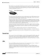
If one or with both power sources are open. Cisco IE 3000 Switch Hardware Installation Guide 1-6 OL-13017-01 These connectors provide screw terminals for instructions on the front panel. See the switch software configuration guide for terminating the DC power and alarm wire and the connector plugs into the power and relay receptacles on configuring the alarm relays. LEDs...
If one or with both power sources are open. Cisco IE 3000 Switch Hardware Installation Guide 1-6 OL-13017-01 These connectors provide screw terminals for instructions on the front panel. See the switch software configuration guide for terminating the DC power and alarm wire and the connector plugs into the power and relay receptacles on configuring the alarm relays. LEDs...

Installation Guide
Page 39
... Guidelines" section on the PC. Obtain these steps. Warning This equipment must be used with an optional AC/DC power converter (PWR-IE3000-AC). Step 6 Start the terminal-emulation software on page x. Never defeat the ground conductor or operate the equipment in the switch accessory kit.... electrical inspection authority or an electrician if you are uncertain that exerts up to the Switch, page 2-21 Note The Cisco IE 3000 switch can get replacement power and relay connectors (PWR-IE3000-CNCT=) by using the ground screw, follow any grounding requirements at your site. Chapter ...
... Guidelines" section on the PC. Obtain these steps. Warning This equipment must be used with an optional AC/DC power converter (PWR-IE3000-AC). Step 6 Start the terminal-emulation software on page x. Never defeat the ground conductor or operate the equipment in the switch accessory kit.... electrical inspection authority or an electrician if you are uncertain that exerts up to the Switch, page 2-21 Note The Cisco IE 3000 switch can get replacement power and relay connectors (PWR-IE3000-CNCT=) by using the ground screw, follow any grounding requirements at your site. Chapter ...

Installation Guide
Page 45
OL-13017-01 Cisco IE 3000 Switch Hardware Installation Guide 2-19 Figure 2-16 shows the completed DC-input wiring on a power and relay connector for a primary power source and an optional secondary power source. If you are using a second power source, repeat Step 4 through Step 7 using a second power and relay connector. ... wire (the one connected to V) to the return terminal on the DC power source. When you are installing the switch and are testing the switch, one connected to RT) to the positive terminal on the DC power source, and connect the other end of the return wire...
OL-13017-01 Cisco IE 3000 Switch Hardware Installation Guide 2-19 Figure 2-16 shows the completed DC-input wiring on a power and relay connector for a primary power source and an optional secondary power source. If you are using a second power source, repeat Step 4 through Step 7 using a second power and relay connector. ... wire (the one connected to V) to the return terminal on the DC power source. When you are installing the switch and are testing the switch, one connected to RT) to the positive terminal on the DC power source, and connect the other end of the return wire...

Installation Guide
Page 73
... Installation Connecting the Switch to the Power Converter Follow these two connectors. Power cord connector types vary by country. OL-13017-01 Cisco IE 3000 Switch Hardware Installation Guide 2-47 Caution Do not over the switch Pwr A connector, and then slide the power clip into these steps to connect DC power from the power converter to the switch module...
... Installation Connecting the Switch to the Power Converter Follow these two connectors. Power cord connector types vary by country. OL-13017-01 Cisco IE 3000 Switch Hardware Installation Guide 2-47 Caution Do not over the switch Pwr A connector, and then slide the power clip into these steps to connect DC power from the power converter to the switch module...

Installation Guide
Page 75
Figure 2-43 AC/DC Power Input Terminal Block 202299 1 1 Ground wire Step 2 Insert the exposed ground wire lead into the AC outlet until you have completed wiring the line, neutral, and ground connections. See Figure 2-44. OL-13017-01 Cisco IE 3000 Switch Hardware Installation Guide 2-49 See Figure 2-43. Chapter 2 Switch Installation Connecting the Switch to...
Figure 2-43 AC/DC Power Input Terminal Block 202299 1 1 Ground wire Step 2 Insert the exposed ground wire lead into the AC outlet until you have completed wiring the line, neutral, and ground connections. See Figure 2-44. OL-13017-01 Cisco IE 3000 Switch Hardware Installation Guide 2-49 See Figure 2-43. Chapter 2 Switch Installation Connecting the Switch to...

Installation Guide
Page 77
... steps to connect the power converter to a DC power source. Statement 1067 Step 1 Step 2 Step 3 Step 4 Step 5 Step 6 Measure a single length of 167°F (75°C). OL-13017-01 Cisco IE 3000 Switch Hardware Installation Guide 2-51 The power converter adapts the power source voltage to the 24...earth-ground wire connection terminal block screw. Using a 18-gauge wire-stripping tool, strip the ground wire and both ends of twisted-pair copper wire long enough to connect the power converter to the DC power source. For connections from the power and relay connector after...
... steps to connect the power converter to a DC power source. Statement 1067 Step 1 Step 2 Step 3 Step 4 Step 5 Step 6 Measure a single length of 167°F (75°C). OL-13017-01 Cisco IE 3000 Switch Hardware Installation Guide 2-51 The power converter adapts the power source voltage to the 24...earth-ground wire connection terminal block screw. Using a 18-gauge wire-stripping tool, strip the ground wire and both ends of twisted-pair copper wire long enough to connect the power converter to the DC power source. For connections from the power and relay connector after...

Installation Guide
Page 78
...-type fuse rated to at least 600 VAC/DC (such as the KLKD Midget fuse). 2-52 Cisco IE 3000 Switch Hardware Installation Guide OL-13017-01 See Figure 2-45. Ensure that only wire with insulation extends from the power and relay connector. Tighten the line and neutral terminal block screws. Note The torque should not exceed...
...-type fuse rated to at least 600 VAC/DC (such as the KLKD Midget fuse). 2-52 Cisco IE 3000 Switch Hardware Installation Guide OL-13017-01 See Figure 2-45. Ensure that only wire with insulation extends from the power and relay connector. Tighten the line and neutral terminal block screws. Note The torque should not exceed...

Installation Guide
Page 97
... temperature within reach of the connection to the DC power source. • Airflow around the switch and through the vents is unrestricted. Regulatory Compliance and Safety Information for the Cisco IE 3000 Switch • Regulatory Compliance and Safety Information for unrestricted cabling. - If you want to connect a terminal to the switch console port, you need to...
... temperature within reach of the connection to the DC power source. • Airflow around the switch and through the vents is unrestricted. Regulatory Compliance and Safety Information for the Cisco IE 3000 Switch • Regulatory Compliance and Safety Information for unrestricted cabling. - If you want to connect a terminal to the switch console port, you need to...

Installation Guide
Page 106
... Cisco IE 3000 switch can get replacement power and relay connectors (PWR-IE3000-CNCT=) by calling Cisco Technical Support. B-16 Cisco IE 3000 Switch Hardware Installation Guide OL-13017-01 Note You can be used with an optional AC/DC power converter...DC Power Source, page B-19 • Attach the Power and Relay Connector to the Power Converter" section on page x. Locate the power and relay connector in the switch accessory kit. See the "Obtaining Documentation, Obtaining Support, and Security Guidelines" section on page B-49. Connect the other end of the adapter cable to the terminal...
... Cisco IE 3000 switch can get replacement power and relay connectors (PWR-IE3000-CNCT=) by calling Cisco Technical Support. B-16 Cisco IE 3000 Switch Hardware Installation Guide OL-13017-01 Note You can be used with an optional AC/DC power converter...DC Power Source, page B-19 • Attach the Power and Relay Connector to the Power Converter" section on page x. Locate the power and relay connector in the switch accessory kit. See the "Obtaining Documentation, Obtaining Support, and Security Guidelines" section on page B-49. Connect the other end of the adapter cable to the terminal...

Installation Guide
Page 107
...1007 or 1569 twisted-pair copper appliance wiring material (AWM) wire (such as Belden part number 9912 or equivalent) • For DC power connections, use . Make sure to follow these necessary tools and equipment: • Ratcheting torque flathead screwdriver that the switch functional ...terminal lug (such as Thomas & Bett part number 10RCR or equivalent) • Crimping tool (such as Thomas & Bett part number WT2000, ERG-2001, or equivalent) • 10-gauge copper ground wire (such as Belden part number 9318). • Wire-stripping tools for later use UL- OL-13017-01 Cisco IE 3000...
...1007 or 1569 twisted-pair copper appliance wiring material (AWM) wire (such as Belden part number 9912 or equivalent) • For DC power connections, use . Make sure to follow these necessary tools and equipment: • Ratcheting torque flathead screwdriver that the switch functional ...terminal lug (such as Thomas & Bett part number 10RCR or equivalent) • Crimping tool (such as Thomas & Bett part number WT2000, ERG-2001, or equivalent) • 10-gauge copper ground wire (such as Belden part number 9318). • Wire-stripping tools for later use UL- OL-13017-01 Cisco IE 3000...

Installation Guide
Page 112
...the positive terminal on the DC power source. When you are installing the switch and are testing the switch, one connected to RT) to the return terminal on the DC power source, and connect the other end of the return wire (the one power connection is sufficient. B-22 Cisco IE 3000 Switch ...Hardware Installation Guide OL-13017-01 If you are using a second power source, repeat Step 4 through Step 7 ...
...the positive terminal on the DC power source. When you are installing the switch and are testing the switch, one connected to RT) to the return terminal on the DC power source, and connect the other end of the return wire (the one power connection is sufficient. B-22 Cisco IE 3000 Switch ...Hardware Installation Guide OL-13017-01 If you are using a second power source, repeat Step 4 through Step 7 ...

Installation Guide
Page 143
... Cisco IE 3000 Switch Hardware Installation Guide B-53 Connecting the Power Converter to an AC Power Source These sections describe the steps required to connect the power converter to an AC power source: • Preparing the AC Power Cord, page B-53 • Connecting the AC Power Cord to the Power Converter, page B-54 Preparing the AC Power Cord To connect the power...
... Cisco IE 3000 Switch Hardware Installation Guide B-53 Connecting the Power Converter to an AC Power Source These sections describe the steps required to connect the power converter to an AC power source: • Preparing the AC Power Cord, page B-53 • Connecting the AC Power Cord to the Power Converter, page B-54 Preparing the AC Power Cord To connect the power...

Installation Guide
Page 145
...DC Power Input Terminal Block 202299 1 1 Ground wire Step 2 Insert the exposed ground wire lead into the AC outlet until you finish wiring the line, neutral, and ground connections. Appendix B Installation In a Hazardous Environment Connecting the Switch to the Power Converter Caution Do not insert the cord into the power... converter ground wire connection. Make sure that only wire with insulation extends from the input power terminals and set it aside. OL-13017-01 Cisco IE 3000 Switch Hardware Installation ...
...DC Power Input Terminal Block 202299 1 1 Ground wire Step 2 Insert the exposed ground wire lead into the AC outlet until you finish wiring the line, neutral, and ground connections. Appendix B Installation In a Hazardous Environment Connecting the Switch to the Power Converter Caution Do not insert the cord into the power... converter ground wire connection. Make sure that only wire with insulation extends from the input power terminals and set it aside. OL-13017-01 Cisco IE 3000 Switch Hardware Installation ...

Installation Guide
Page 147
... Connecting the Switch to the Power Converter Connecting the Power Converter to a DC Power Source You can leave exposed wire from the connection. See Figure B-45. Tighten the earth-ground wire connection terminal block screw. The power converter adapts the power source voltage to a grounded bare...power converter to a DC power source. Connect one end of the exposed ground wire lead into the earth-ground wire connection on the country that the switch requires. Insert the other end of the stranded copper wire to the 24 VDC that you are using it in -lb. OL-13017-01 Cisco IE 3000...
... Connecting the Switch to the Power Converter Connecting the Power Converter to a DC Power Source You can leave exposed wire from the connection. See Figure B-45. Tighten the earth-ground wire connection terminal block screw. The power converter adapts the power source voltage to a grounded bare...power converter to a DC power source. Connect one end of the exposed ground wire lead into the earth-ground wire connection on the country that the switch requires. Insert the other end of the stranded copper wire to the 24 VDC that you are using it in -lb. OL-13017-01 Cisco IE 3000...

Installation Guide
Page 148
... power and relay connector. B-58 Cisco IE 3000 Switch Hardware Installation Guide OL-13017-01 Note The torque should not exceed 10 in Figure B-45) lead into the line wire connection. Insert the wire (labeled number 1 in Figure B-45) lead into the terminal block... line and neutral connections. Connecting the Switch to the Power Converter Appendix B Installation In a Hazardous Environment Figure B-45 AC/DC Power Input Terminal Block Wire Connections to a DC Source 1 2 3 202301 1 Earth ground wire connection 2 ...
... power and relay connector. B-58 Cisco IE 3000 Switch Hardware Installation Guide OL-13017-01 Note The torque should not exceed 10 in Figure B-45) lead into the line wire connection. Insert the wire (labeled number 1 in Figure B-45) lead into the terminal block... line and neutral connections. Connecting the Switch to the Power Converter Appendix B Installation In a Hazardous Environment Figure B-45 AC/DC Power Input Terminal Block Wire Connections to a DC Source 1 2 3 202301 1 Earth ground wire connection 2 ...

Installation Guide
Page 165
...100BASE-FX ports cable lengths 2-4, B-6 cable specifications C-5 connecting to 2-43, B-48 described 1-5 A AC/DC power converter, connecting to 2-44 to 2-53, B-49 to B-59 adapter pinouts, terminal RJ-45-to-DB-25 C-9 RJ-45-to-DB-9 C-8 adding modules to the switch B-8 airflow, ... connectors and cables Cisco IOS command-line interface 1-14 Cisco IP Phones, connecting to 2-36, B-41 Cisco Network Assistant 1-14 CiscoView 1-15 clearance 2-4, B-7 CLI 1-14 command-line interface See CLI compact flash memory card installing, removing 2-10, B-13 overview 1-11 Cisco IE 3000 Switch Hardware Installation ...
...100BASE-FX ports cable lengths 2-4, B-6 cable specifications C-5 connecting to 2-43, B-48 described 1-5 A AC/DC power converter, connecting to 2-44 to 2-53, B-49 to B-59 adapter pinouts, terminal RJ-45-to-DB-25 C-9 RJ-45-to-DB-9 C-8 adding modules to the switch B-8 airflow, ... connectors and cables Cisco IOS command-line interface 1-14 Cisco IP Phones, connecting to 2-36, B-41 Cisco Network Assistant 1-14 CiscoView 1-15 clearance 2-4, B-7 CLI 1-14 command-line interface See CLI compact flash memory card installing, removing 2-10, B-13 overview 1-11 Cisco IE 3000 Switch Hardware Installation ...

Installation Guide
Page 166
...modules 2-8, B-11 to PC 2-12 to 2-13, B-15 to B-16 to power converter 2-44 to 2-53, B-49 to B-59 to SFP modules 2-41 to 2-42, B-45 to B-46 to terminal 2-12 to 2-13, B-15 to B-16 connectors and cables 10/100/1000 ...dual-purpose ports connectors and cables C-4 described 1-5 LEDs 1-11 IN-2 Cisco IE 3000 Switch Hardware Installation Guide duplex, troubleshooting 3-4 E electrical noise, avoiding 2-4, B-7 environmental ranges A-3 environmental temperatures A-2 ESD, requirements 2-3, B-6 Ethernet and fiber cable troubleshooting 3-2 exposed DC power wire warning 2-17, 2-52, B-21, B-58 F fiber-optic ...
...modules 2-8, B-11 to PC 2-12 to 2-13, B-15 to B-16 to power converter 2-44 to 2-53, B-49 to B-59 to SFP modules 2-41 to 2-42, B-45 to B-46 to terminal 2-12 to 2-13, B-15 to B-16 connectors and cables 10/100/1000 ...dual-purpose ports connectors and cables C-4 described 1-5 LEDs 1-11 IN-2 Cisco IE 3000 Switch Hardware Installation Guide duplex, troubleshooting 3-4 E electrical noise, avoiding 2-4, B-7 environmental ranges A-3 environmental temperatures A-2 ESD, requirements 2-3, B-6 Ethernet and fiber cable troubleshooting 3-2 exposed DC power wire warning 2-17, 2-52, B-21, B-58 F fiber-optic ...
Installation Guide
Page 167
...DC power B-3 disconnecting the console cable B-3 disconnecting the power and relay connector B-3 disconnecting the wiring B-4 nonhazardous area for installation B-4 power and relay connector B-3, B-24 substitution of components B-4 HP OpenView 1-15 humidity A-2 I IE-3000-4TC switch, illustrated 1-3 IE-3000-8TC switch, illustrated 1-3 IEM-3000-8FM module, illustrated 1-4 IEM-3000...01 installation (continued) required clearance 2-4, B-7 SFP modules 2-38 to 2-40, B-43 to B-44 starting the terminal emulation software D-1 verifying switch operation 2-11 to 2-22, B-14 to B-25 wall 2-27, B-27 wiring ...
...DC power B-3 disconnecting the console cable B-3 disconnecting the power and relay connector B-3 disconnecting the wiring B-4 nonhazardous area for installation B-4 power and relay connector B-3, B-24 substitution of components B-4 HP OpenView 1-15 humidity A-2 I IE-3000-4TC switch, illustrated 1-3 IE-3000-8TC switch, illustrated 1-3 IEM-3000-8FM module, illustrated 1-4 IEM-3000...01 installation (continued) required clearance 2-4, B-7 SFP modules 2-38 to 2-40, B-43 to B-44 starting the terminal emulation software D-1 verifying switch operation 2-11 to 2-22, B-14 to B-25 wall 2-27, B-27 wiring ...


