Hardware Installation Guide
Page 20
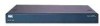
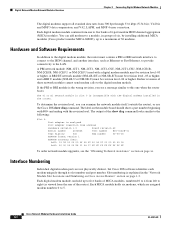
... can be installed per chassis. Cisco Network Modules Hardware Installation Guide 1-6 OL-2485-20 Cisco IOS Software Releases and Cisco Network Modules Chapter 1 Overview of Cisco Network Modules for Cisco Access Routers Table 1-1 Network Module Slots Available on Cisco Access Routers (continued) Cisco Router Cisco 3825 routers Cisco 3845 routers Number of cards and modules, go to the Software Advisor at the login dialog box and follow the instructions that appear. Extended single-wide Extension voice 2 Double-wide Slot 1, slot 3 Removing the slot divider changes slot numbering as...
... can be installed per chassis. Cisco Network Modules Hardware Installation Guide 1-6 OL-2485-20 Cisco IOS Software Releases and Cisco Network Modules Chapter 1 Overview of Cisco Network Modules for Cisco Access Routers Table 1-1 Network Module Slots Available on Cisco Access Routers (continued) Cisco Router Cisco 3825 routers Cisco 3845 routers Number of cards and modules, go to the Software Advisor at the login dialog box and follow the instructions that appear. Extended single-wide Extension voice 2 Double-wide Slot 1, slot 3 Removing the slot divider changes slot numbering as...
Hardware Installation Guide
Page 46
...Overview of Cisco Network Modules for Cisco Access Routers • Software configuration-Basic to advanced software configuration procedures, sample configurations • Software references-Command references, system message guides • Software release information-Supported products, caveats • Software release tools-Cisco Feature Navigator II, Cisco IOS Upgrade Planner, software downloads, security notices and advisories Cisco IOS Software Configuration Documents To find initial configuration instructions specific to the Cisco router you are using, access the documents located at...
...Overview of Cisco Network Modules for Cisco Access Routers • Software configuration-Basic to advanced software configuration procedures, sample configurations • Software references-Command references, system message guides • Software release information-Supported products, caveats • Software release tools-Cisco Feature Navigator II, Cisco IOS Upgrade Planner, software downloads, security notices and advisories Cisco IOS Software Configuration Documents To find initial configuration instructions specific to the Cisco router you are using, access the documents located at...

Hardware Installation Guide
Page 69
... the interface card and to board components. Handle the network module by the faceplate only to avoid damage to the network module, turn off electrical power and disconnect network cables before starting OIR procedures. Replacing Network Modules in its place. or 2-slot network modules, you remove a network module, install the same model network module in Cisco Access Routers with Cisco IOS software. OIR procedures require some interaction with Online Insertion and Removal Support Online insertion and removal (OIR) provides uninterrupted network operation, maintains routing...
... the interface card and to board components. Handle the network module by the faceplate only to avoid damage to the network module, turn off electrical power and disconnect network cables before starting OIR procedures. Replacing Network Modules in its place. or 2-slot network modules, you remove a network module, install the same model network module in Cisco Access Routers with Cisco IOS software. OIR procedures require some interaction with Online Insertion and Removal Support Online insertion and removal (OIR) provides uninterrupted network operation, maintains routing...
Hardware Installation Guide
Page 143
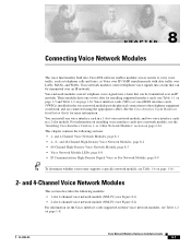
... over LANs, MANs, and WANs. This chapter contains the following modules: • 1-slot 2-channel voice network module (NM-1V) (see Figure 8-1) • 2-slot 4-channel voice network module (NM-2V) (see Figure 8-2) For information on the Cisco interface cards supported on these voice network modules, see Table 1-6 on page 1-8). CH A P T E R 8 Connecting Voice Network Modules The voice functionality built into Cisco IOS software enables modular access routers to the telephony equipment or network, and are connected using the appropriate cables. or 2-Slot Network Modules...
... over LANs, MANs, and WANs. This chapter contains the following modules: • 1-slot 2-channel voice network module (NM-1V) (see Figure 8-1) • 2-slot 4-channel voice network module (NM-2V) (see Figure 8-2) For information on the Cisco interface cards supported on these voice network modules, see Table 1-6 on page 1-8). CH A P T E R 8 Connecting Voice Network Modules The voice functionality built into Cisco IOS software enables modular access routers to the telephony equipment or network, and are connected using the appropriate cables. or 2-Slot Network Modules...
Hardware Installation Guide
Page 160
... or BRI network interface to connect to the ISDN channel, and another interface, such as viewed from one to five banks of these network modules cannot send modem calls to this one when the router boots: The T1 or E1 network module in slot 0 is incompatible with the digital modems installed in the "Network Module Slot Locations and Numbering on Cisco Access Routers" section on the module board should show a part number beginning with...
... or BRI network interface to connect to the ISDN channel, and another interface, such as viewed from one to five banks of these network modules cannot send modem calls to this one when the router boots: The T1 or E1 network module in slot 0 is incompatible with the digital modems installed in the "Network Module Slot Locations and Numbering on Cisco Access Routers" section on the module board should show a part number beginning with...
Hardware Installation Guide
Page 208
... Duplexer Replacement Instructions • Cisco Multipoint Headend Power Feed Panel Replacement Instructions • Cisco Multipoint Headend Wireless Transverter Replacement Instructions • Cisco Wireless Transverter Hail Shield Installation Instructions 15-4 Cisco Network Modules Hardware Installation Guide OL-2485-20 Yellow indicates loss of the radio link. Yellow means that the radio link is down. Related Documents Chapter 15 Connecting Wireless Multipoint Network Modules Table 15-1 Wireless Multipoint Network Module LEDs (continued) LED CARRIER OUT OF SERVICE MINOR...
... Duplexer Replacement Instructions • Cisco Multipoint Headend Power Feed Panel Replacement Instructions • Cisco Multipoint Headend Wireless Transverter Replacement Instructions • Cisco Wireless Transverter Hail Shield Installation Instructions 15-4 Cisco Network Modules Hardware Installation Guide OL-2485-20 Yellow indicates loss of the radio link. Yellow means that the radio link is down. Related Documents Chapter 15 Connecting Wireless Multipoint Network Modules Table 15-1 Wireless Multipoint Network Module LEDs (continued) LED CARRIER OUT OF SERVICE MINOR...

Hardware Installation Guide
Page 210
... Power fail port Note Port 18 is hard-wired to the network using an RJ-21 Amphenol connector on the card support up to the central office (CO) in Figure 16-1. 16-2 Cisco Network Modules Hardware Installation Guide OL-2485-20 Tip To maintain an emergency connection during power outages. In this case, a DSP expansion module must be used in Table 16-2. Physical ports are needed. High-Density Analog Telephony Network Module Chapter 16 Connecting High...
... Power fail port Note Port 18 is hard-wired to the network using an RJ-21 Amphenol connector on the card support up to the central office (CO) in Figure 16-1. 16-2 Cisco Network Modules Hardware Installation Guide OL-2485-20 Tip To maintain an emergency connection during power outages. In this case, a DSP expansion module must be used in Table 16-2. Physical ports are needed. High-Density Analog Telephony Network Module Chapter 16 Connecting High...
Hardware Installation Guide
Page 212
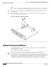
... expansion board is correctly in Figure 16-4. Adding Port Expansion Modules Chapter 16 Connecting High-Density Analog Telephony Network Modules Note Be sure to press firmly on the bracket to increase the number of ports supported on the network module. Step 2 Step 3 Insert the screws from the hardware kit through the DSP expansion module into the router, as shown in place. 16-4 Cisco Network Modules Hardware Installation Guide OL-2485-20
... expansion board is correctly in Figure 16-4. Adding Port Expansion Modules Chapter 16 Connecting High-Density Analog Telephony Network Modules Note Be sure to press firmly on the bracket to increase the number of ports supported on the network module. Step 2 Step 3 Insert the screws from the hardware kit through the DSP expansion module into the router, as shown in place. 16-4 Cisco Network Modules Hardware Installation Guide OL-2485-20
Hardware Installation Guide
Page 217
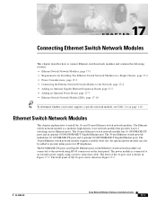
...17-7 • Ethernet Switch Network Module LEDs, page 17-10 Tip To determine whether your router supports a specific network module, see Table 1-6 on the front panel. The 16-port Ethernet switch network module has 16 10/100BASE-TX ports and an optional 10/100/1000BASE-T Gigabit Ethernet port. The Ethernet switch network module is connected to an external power supply using RJ-45 connectors on page 1-16. The front panel of the 16-port card is shown in Figure 17-1. and 36-port Ethernet switch network modules. The power module is a modular, high-density voice network module that...
...17-7 • Ethernet Switch Network Module LEDs, page 17-10 Tip To determine whether your router supports a specific network module, see Table 1-6 on the front panel. The 16-port Ethernet switch network module has 16 10/100BASE-TX ports and an optional 10/100/1000BASE-T Gigabit Ethernet port. The Ethernet switch network module is connected to an external power supply using RJ-45 connectors on page 1-16. The front panel of the 16-port card is shown in Figure 17-1. and 36-port Ethernet switch network modules. The power module is a modular, high-density voice network module that...

Hardware Installation Guide
Page 220
...-DC router, shielded cables are made aware of a special tool, lock and key, or other security means. Connecting the Ethernet Switch Network Module to the Network Chapter 17 Connecting Ethernet Switch Network Modules Connecting the Ethernet Switch Network Module to the Network Warning Voltages that present a shock hazard can be accessed only through the use of the hazard. Avoid using such interconnection methods unless the exposed metal parts are in a restricted access location and users and service people...
...-DC router, shielded cables are made aware of a special tool, lock and key, or other security means. Connecting the Ethernet Switch Network Module to the Network Chapter 17 Connecting Ethernet Switch Network Modules Connecting the Ethernet Switch Network Module to the Network Warning Voltages that present a shock hazard can be accessed only through the use of the hazard. Avoid using such interconnection methods unless the exposed metal parts are in a restricted access location and users and service people...
Hardware Installation Guide
Page 221
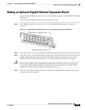
... 5x 12x 4x 11x 3x 10x 2x 9x 1x 0x 8x 0x Ext Pwr -48V GE 1100/01000/ Base-Tx EN 62426 Step 2 Step 3 Gigabit Ethernet port cover Guide the external connector through the Gigabit Ethernet expansion board into the board connector on the Ethernet Switch Network Module NM- To install a Gigabit Ethernet expansion board, follow these steps: Step 1 Use a Phillips screwdriver to support a 10/100/1000BASE-T Gigabit Ethernet port.
... 5x 12x 4x 11x 3x 10x 2x 9x 1x 0x 8x 0x Ext Pwr -48V GE 1100/01000/ Base-Tx EN 62426 Step 2 Step 3 Gigabit Ethernet port cover Guide the external connector through the Gigabit Ethernet expansion board into the board connector on the Ethernet Switch Network Module NM- To install a Gigabit Ethernet expansion board, follow these steps: Step 1 Use a Phillips screwdriver to support a 10/100/1000BASE-T Gigabit Ethernet port.

Hardware Installation Guide
Page 240
... default. • With a single power supply, these routers can have no preference about which the Cisco EtherSwitch service modules are configured to be grounded at both Cisco EtherSwitch service modules in the stack within 10 seconds. This is required. Each port can trunk to become the stack master, power up that are widely available. 18-14 Cisco Network Modules Hardware Installation Guide OL-2485-20 A 10/100/1000 Gigabit Ethernet (GE) port or a SFP module port can be used to connect...
... default. • With a single power supply, these routers can have no preference about which the Cisco EtherSwitch service modules are configured to be grounded at both Cisco EtherSwitch service modules in the stack within 10 seconds. This is required. Each port can trunk to become the stack master, power up that are widely available. 18-14 Cisco Network Modules Hardware Installation Guide OL-2485-20 A 10/100/1000 Gigabit Ethernet (GE) port or a SFP module port can be used to connect...

Hardware Installation Guide
Page 250
...# copy tftp running configuration of the slot. Align the replacement CE network module with the connector on . Reconnect the network interface cables previously removed in Step 7. Check that the network module LEDs are on the backplane. Initiate a CE network module console access session with a CE Network Module Step 2 Save the running -config tftp-server-address filename Step 16 Exit the CE network module console access session by pressing Control-Shift-6, followed by x. 19-6 Cisco Network Modules Hardware Installation Guide OL-2485-20 Open CE-netmodule...
...# copy tftp running configuration of the slot. Align the replacement CE network module with the connector on . Reconnect the network interface cables previously removed in Step 7. Check that the network module LEDs are on the backplane. Initiate a CE network module console access session with a CE Network Module Step 2 Save the running -config tftp-server-address filename Step 16 Exit the CE network module console access session by pressing Control-Shift-6, followed by x. 19-6 Cisco Network Modules Hardware Installation Guide OL-2485-20 Open CE-netmodule...

Hardware Installation Guide
Page 331
... module and access points executable file, and Cisco WLAN controller module configuration. 31 C H A P T E R Connecting Cisco Wireless LAN Controller Modules This chapter describes how to connect Cisco wireless LAN (WLAN) controller modules (WLCM) and contains the following URL: http://www.cisco.com/en/US/products/ps6305/products_configuration_guide_book09186a00804f988b. It is supported only in the Cisco 2821 and Cisco 2851 integrated services routers. Tip For information about which Cisco routers support the Cisco WLAN controller module, see the Cisco Wireless LAN Solution Product Guide...
... module and access points executable file, and Cisco WLAN controller module configuration. 31 C H A P T E R Connecting Cisco Wireless LAN Controller Modules This chapter describes how to connect Cisco wireless LAN (WLAN) controller modules (WLCM) and contains the following URL: http://www.cisco.com/en/US/products/ps6305/products_configuration_guide_book09186a00804f988b. It is supported only in the Cisco 2821 and Cisco 2851 integrated services routers. Tip For information about which Cisco routers support the Cisco WLAN controller module, see the Cisco Wireless LAN Solution Product Guide...

Hardware Installation Guide
Page 333
Chapter 31 Connecting Cisco Wireless LAN Controller Modules Online Insertion and Removal with a Cisco Wireless LAN Controller Module Online Insertion and Removal with the router in privileged EXEC mode. Note OIR of other interfaces. To save the configuration file, follow these steps with a Cisco Wireless LAN Controller Module The Cisco integrated services routers (ISRs) allow you to network users, maintains routing information, and ensures session preservation. OIR of router. Open Set the TFTP server IP address from the WLAN controller module console access session: (WLAN-Controller...
Chapter 31 Connecting Cisco Wireless LAN Controller Modules Online Insertion and Removal with a Cisco Wireless LAN Controller Module Online Insertion and Removal with the router in privileged EXEC mode. Note OIR of other interfaces. To save the configuration file, follow these steps with a Cisco Wireless LAN Controller Module The Cisco integrated services routers (ISRs) allow you to network users, maintains routing information, and ensures session preservation. OIR of router. Open Set the TFTP server IP address from the WLAN controller module console access session: (WLAN-Controller...

Hardware Installation Guide
Page 335
... image available on the hard disc! Cisco is necessary for additional boot options... Software Copyright Cisco Systems, Inc. Web Server: ok CLI: ok Secure Web: ok (WLAN-Controller) Enter User Name (or 'Recover-Config' to reset configuration to reset Service Module wlan-controller1/0. Router(config)# interface wlan-controller 1/0 Router(config-if)# ip address 192.0.2.254 255.255.255.0 Router(config-if)# no shutdown Router(config-if)# end Router# Router# Initiate a WLAN controller module console access session and access the bootloader prompt using the following command: Note The...
... image available on the hard disc! Cisco is necessary for additional boot options... Software Copyright Cisco Systems, Inc. Web Server: ok CLI: ok Secure Web: ok (WLAN-Controller) Enter User Name (or 'Recover-Config' to reset configuration to reset Service Module wlan-controller1/0. Router(config)# interface wlan-controller 1/0 Router(config-if)# ip address 192.0.2.254 255.255.255.0 Router(config-if)# no shutdown Router(config-if)# end Router# Router# Initiate a WLAN controller module console access session and access the bootloader prompt using the following command: Note The...

Hardware Installation Guide
Page 336
... the WLAN controller module console access session: (WLAN-Controller) > transfer download serverip 192.0.2.24 Step 6 Set the datatype configuration using the following command: (WLAN-Controller) > transfer download datatype configuration Step 7 Set the running .bin Data Type Config File Encryption Disabled WARNING: Config File Encryption Disabled Are you sure you want to start? (y/n) y Tftp Config transfer starting. Tip For information on obtaining documentation, see the "Obtaining Documentation" section on page xi. 31-6 Cisco Network Modules Hardware Installation Guide OL...
... the WLAN controller module console access session: (WLAN-Controller) > transfer download serverip 192.0.2.24 Step 6 Set the datatype configuration using the following command: (WLAN-Controller) > transfer download datatype configuration Step 7 Set the running .bin Data Type Config File Encryption Disabled WARNING: Config File Encryption Disabled Are you sure you want to start? (y/n) y Tftp Config transfer starting. Tip For information on obtaining documentation, see the "Obtaining Documentation" section on page xi. 31-6 Cisco Network Modules Hardware Installation Guide OL...

Hardware Installation Guide
Page 337
....com/en/US/products/hw/wireless/tsd_products_support_category_home.html OL-2485-20 Cisco Network Modules Hardware Installation Guide 31-7 Cisco Wireless LAN Controller Module Documentation For additional information about WLAN support on the Cisco wireless LAN controller module, see the "Cisco IOS Software Documentation" section on installing and removing Cisco modules, see the Cisco Network Modules Hardware Installation Guide (this document). Chapter 31 Connecting Cisco Wireless LAN Controller Modules Related Documents Hardware Documentation For general information on page 1-31...
....com/en/US/products/hw/wireless/tsd_products_support_category_home.html OL-2485-20 Cisco Network Modules Hardware Installation Guide 31-7 Cisco Wireless LAN Controller Module Documentation For additional information about WLAN support on the Cisco wireless LAN controller module, see the "Cisco IOS Software Documentation" section on installing and removing Cisco modules, see the Cisco Network Modules Hardware Installation Guide (this document). Chapter 31 Connecting Cisco Wireless LAN Controller Modules Related Documents Hardware Documentation For general information on page 1-31...

Hardware Installation Guide
Page 340
... LAN Controller Network Modules Chapter 32 Connecting Cisco Wireless LAN Controller Enhanced Network Modules Figure 32-1 Cisco WLAN Controller Network Module Faceplate SHUTDOWN: GRACEFUL 4 s CF NOT SUPPORTED LINK ACT GigE SYS NOT SUPPORTED USB EN LINK ACT PWR/SYS Status of the network module On-Detected by the host Cisco IOS software and enabled. Off-Inactive. Off-Disabled. EN Status of Gigabit Ethernet link On-Link is not supported in progress. On-Application is disabled. Flashing-Application detected CompactFlash at bootup. 32-2 Cisco Network Modules Hardware...
... LAN Controller Network Modules Chapter 32 Connecting Cisco Wireless LAN Controller Enhanced Network Modules Figure 32-1 Cisco WLAN Controller Network Module Faceplate SHUTDOWN: GRACEFUL 4 s CF NOT SUPPORTED LINK ACT GigE SYS NOT SUPPORTED USB EN LINK ACT PWR/SYS Status of the network module On-Detected by the host Cisco IOS software and enabled. Off-Inactive. Off-Disabled. EN Status of Gigabit Ethernet link On-Link is not supported in progress. On-Application is disabled. Flashing-Application detected CompactFlash at bootup. 32-2 Cisco Network Modules Hardware...

Hardware Installation Guide
Page 342
... Slide the network module out of the slot. Open (Cisco Controller) > 32-4 Cisco Network Modules Hardware Installation Guide OL-2485-20 Online Insertion and Removal of Cisco Network Modules Chapter 32 Connecting Cisco Wireless LAN Controller Enhanced Network Modules For a description of informational and error messages that the power (PWR) and enable (EN) LEDs on the front panel are also on. Open User: Exit the network module session by using the following command: Router# service-module integrated-service-engine slot/unit shutdown Shut down the network module interface: Router (config...
... Slide the network module out of the slot. Open (Cisco Controller) > 32-4 Cisco Network Modules Hardware Installation Guide OL-2485-20 Online Insertion and Removal of Cisco Network Modules Chapter 32 Connecting Cisco Wireless LAN Controller Enhanced Network Modules For a description of informational and error messages that the power (PWR) and enable (EN) LEDs on the front panel are also on. Open User: Exit the network module session by using the following command: Router# service-module integrated-service-engine slot/unit shutdown Shut down the network module interface: Router (config...


