
Installation Guide
Page 21
... Removal" section on the second-generation Versatile Interface Processors (VIP2s) in the Cisco 7500 series routers, in Cisco 7000 series routers using the 7000 Series Route Switch Processor (RSP7000) and 7000 series Chassis Interface (RSP7000CI), and in the Cisco 7206 support OIR. OL-5102-02 Cisco 7206 Installation and Configuration Guide 1-3 Note The I /O controller from left to Figure 1-2). Note...
... Removal" section on the second-generation Versatile Interface Processors (VIP2s) in the Cisco 7500 series routers, in Cisco 7000 series routers using the 7000 Series Route Switch Processor (RSP7000) and 7000 series Chassis Interface (RSP7000CI), and in the Cisco 7206 support OIR. OL-5102-02 Cisco 7206 Installation and Configuration Guide 1-3 Note The I /O controller from left to Figure 1-2). Note...

Installation Guide
Page 22
...processing engine AC-input or network services engine power supply Power switch Note The network processing engine does not support OIR. The network processing engine has no external connectors or LEDs. The Cisco 7206 router comes equipped with only one 280W DC-input power supply. Adjacent... power supplies in unoccupied power supply bays. The power supply has the router's main power switch and either an AC-input power receptacle or a hardwired DC-input power cable (depending on the type of a Cisco 7206 router configured with a single AC-input power supply. (A power supply filler ...
...processing engine AC-input or network services engine power supply Power switch Note The network processing engine does not support OIR. The network processing engine has no external connectors or LEDs. The Cisco 7206 router comes equipped with only one 280W DC-input power supply. Adjacent... power supplies in unoccupied power supply bays. The power supply has the router's main power switch and either an AC-input power receptacle or a hardwired DC-input power cable (depending on the type of a Cisco 7206 router configured with a single AC-input power supply. (A power supply filler ...
Installation Guide
Page 26
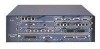
...does not have packet SRAM. - The NPE-200 has an R5000 microprocessor that operates at an internal clock speed of information in preparation for process switching, and packet buffering for SRAM overflow (except in preparation for storing routing tables, network accounting applications, packets of 200 MHz. - The NPE-150... network processing engine. - the NPE-175, NPE-200, and NPE-225 have packet SRAM. - The NPE-100 does not have a boot ROM Cisco 7206 Installation and Configuration Guide 1-8 OL-5102-02 The NPE-175 and NPE-225 have unified cache SRAM that is 32 MB, with up to 128...
...does not have packet SRAM. - The NPE-200 has an R5000 microprocessor that operates at an internal clock speed of information in preparation for process switching, and packet buffering for SRAM overflow (except in preparation for storing routing tables, network accounting applications, packets of 200 MHz. - The NPE-150... network processing engine. - the NPE-175, NPE-200, and NPE-225 have packet SRAM. - The NPE-100 does not have a boot ROM Cisco 7206 Installation and Configuration Guide 1-8 OL-5102-02 The NPE-175 and NPE-225 have unified cache SRAM that is 32 MB, with up to 128...
Installation Guide
Page 27
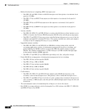
... • Monitoring interface and environmental status • Providing Simple Network Management Protocol (SNMP) management through the console and Telnet interface • Accounting for and switching of data traffic • Booting and reloading images • Managing port adapters (recognition and initialization during online insertion and removal) Figure 1-4 shows the NPE...Temperature sensor DRAM SIMMs U12 Bank 1 U4 U25 Bank 0 U18 NETWORK PROCESSING ENGINE-100 H8822 Captive installation screw Temperature Handle sensor OL-5102-02 Cisco 7206 Installation and Configuration Guide 1-9
... • Monitoring interface and environmental status • Providing Simple Network Management Protocol (SNMP) management through the console and Telnet interface • Accounting for and switching of data traffic • Booting and reloading images • Managing port adapters (recognition and initialization during online insertion and removal) Figure 1-4 shows the NPE...Temperature sensor DRAM SIMMs U12 Bank 1 U4 U25 Bank 0 U18 NETWORK PROCESSING ENGINE-100 H8822 Captive installation screw Temperature Handle sensor OL-5102-02 Cisco 7206 Installation and Configuration Guide 1-9
Installation Guide
Page 43
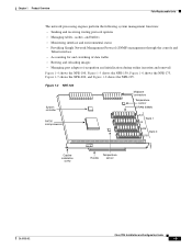
...a minimum of 5A service. Chapter 1 Product Overview Figure 1-15 Cisco 7206 AC-Input Power Supply Field-Replaceable Units H6432 Captive installation screw OK LED Power switch guard Power switch AC-input receptacle Handle The DC-input power supply has DC-input... Cisco 7206 Installation and Configuration Guide 1-25 Figure 1-3 shows a Cisco 7206 with each power supply bay. Figure 1-16 Cisco 7206 DC-Input Power Supply H8618 Captive installation screw OK LED DC-input receptacle Power Power switch switch guard Handle Caution To ensure adequate airflow across the router ...
...a minimum of 5A service. Chapter 1 Product Overview Figure 1-15 Cisco 7206 AC-Input Power Supply Field-Replaceable Units H6432 Captive installation screw OK LED Power switch guard Power switch AC-input receptacle Handle The DC-input power supply has DC-input... Cisco 7206 Installation and Configuration Guide 1-25 Figure 1-3 shows a Cisco 7206 with each power supply bay. Figure 1-16 Cisco 7206 DC-Input Power Supply H8618 Captive installation screw OK LED DC-input receptacle Power Power switch switch guard Handle Caution To ensure adequate airflow across the router ...

Installation Guide
Page 44
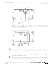
...disconnected and reconnected to the "Environmental Monitoring and Reporting Functions" section on all of the internal components, including the subchassis. Chassis The Cisco 7206 chassis, shown in North America requires a minimum of 13A service. The power OK LED goes off and the power supply shuts itself... of power supply shutdown conditions and thresholds, refer to the source power, and then restarted with the power switch. Figure 1-17 Cisco 7206 Chassis 1 6 3 4 5 2 Cisco 7200 Series 0 H6239 1-26 Cisco 7206 Installation and Configuration Guide OL-5102-02
...disconnected and reconnected to the "Environmental Monitoring and Reporting Functions" section on all of the internal components, including the subchassis. Chassis The Cisco 7206 chassis, shown in North America requires a minimum of 13A service. The power OK LED goes off and the power supply shuts itself... of power supply shutdown conditions and thresholds, refer to the source power, and then restarted with the power switch. Figure 1-17 Cisco 7206 Chassis 1 6 3 4 5 2 Cisco 7200 Series 0 H6239 1-26 Cisco 7206 Installation and Configuration Guide OL-5102-02

Installation Guide
Page 50
... Immediate operator action is required. • Shutdown-The processor has detected a temperature condition that the router is at risk of malfunctioning or being damaged. 1-32 Cisco 7206 Installation and Configuration Guide OL-5102-02 This condition requires immediate operator action. The system continues to ...temperature condition and shut itself down. All DC power remains disabled until you toggle the power switch. All DC power will remain disabled until you toggle the power switch. Before any shutdown, the system logs the status of monitored parameters in physical damage to...
... Immediate operator action is required. • Shutdown-The processor has detected a temperature condition that the router is at risk of malfunctioning or being damaged. 1-32 Cisco 7206 Installation and Configuration Guide OL-5102-02 This condition requires immediate operator action. The system continues to ...temperature condition and shut itself down. All DC power remains disabled until you toggle the power switch. All DC power will remain disabled until you toggle the power switch. Before any shutdown, the system logs the status of monitored parameters in physical damage to...

Installation Guide
Page 57
...8226; Distance limitations for each signal type • The specific cables you need to connect each port adapter. OL-5102-02 Cisco 7206 Installation and Configuration Guide 2-3 Distance Limitations and Interface Specifications The size of this sort in the past, you understand the electrical problems... that is shipped with each interface • Any additional interface equipment you need, such as transceivers, hubs, switches, modems, channel service units (CSUs), or data service units (DSUs) • Cable pinouts if you plan to build your cables ...
...8226; Distance limitations for each signal type • The specific cables you need to connect each port adapter. OL-5102-02 Cisco 7206 Installation and Configuration Guide 2-3 Distance Limitations and Interface Specifications The size of this sort in the past, you understand the electrical problems... that is shipped with each interface • Any additional interface equipment you need, such as transceivers, hubs, switches, modems, channel service units (CSUs), or data service units (DSUs) • Cable pinouts if you plan to build your cables ...
Installation Guide
Page 63
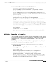
... or the rack-mount brackets In addition, you might need , depending on your configuration: • Host name for the router • Passwords to prevent unauthorized privileged-level access to the EXEC command interpreter and for individual virtual terminal lines • ...8226; Optical bypass switch or concentrator for multimode Fiber Distributed Data Interface (FDDI) connections Initial Configuration Information After you install the chassis and verify that all the hardware is attached. You can connect your system to 2 Mbps. OL-5102-02 Cisco 7206 Installation and Configuration Guide...
... or the rack-mount brackets In addition, you might need , depending on your configuration: • Host name for the router • Passwords to prevent unauthorized privileged-level access to the EXEC command interpreter and for individual virtual terminal lines • ...8226; Optical bypass switch or concentrator for multimode Fiber Distributed Data Interface (FDDI) connections Initial Configuration Information After you install the chassis and verify that all the hardware is attached. You can connect your system to 2 Mbps. OL-5102-02 Cisco 7206 Installation and Configuration Guide...

Installation Guide
Page 80
... supply Power switch 3-12 Cisco 7206 Installation and Configuration Guide OL-5102-02 Providing a Chassis Ground Connection for the Router Chassis Chapter 3 Installing the Cisco 7206 Providing a Chassis Ground Connection for the Router Chassis Before you connect power or turn on your router location and ...2 Phillips screwdriver • Crimping tool large enough to accommodate the diameter of the wire receptacle on each Cisco 7206 router chassis. (Refer to Figure 3-11.) Note Older Cisco 7206 router chassis do not have a 0.63-inch (16.002-mm) spacing between them, and a wire receptacle...
... supply Power switch 3-12 Cisco 7206 Installation and Configuration Guide OL-5102-02 Providing a Chassis Ground Connection for the Router Chassis Chapter 3 Installing the Cisco 7206 Providing a Chassis Ground Connection for the Router Chassis Before you connect power or turn on your router location and ...2 Phillips screwdriver • Crimping tool large enough to accommodate the diameter of the wire receptacle on each Cisco 7206 router chassis. (Refer to Figure 3-11.) Note Older Cisco 7206 router chassis do not have a 0.63-inch (16.002-mm) spacing between them, and a wire receptacle...

Installation Guide
Page 85
... media you fasten to the jackscrews on the MII connector and tighten with your MII cable to the MII port. OL-5102-02 Cisco 7206 Installation and Configuration Guide 3-17 Figure 3-16 MII Port Pin 1 H6538 Jackscrew Pin 21 Table 3-3 lists the pinouts and signals for...switch or hub, the network side of the MII port on the I /O controller MII port. The MII port supports IEEE 802.3u interfaces compliant with ST-type connectors (for 100BASEFX or 100BASET4 physical media (refer to multimode fiber for optical fiber), BNC connectors, and so forth. Chapter 3 Installing the Cisco 7206...
... media you fasten to the jackscrews on the MII connector and tighten with your MII cable to the MII port. OL-5102-02 Cisco 7206 Installation and Configuration Guide 3-17 Figure 3-16 MII Port Pin 1 H6538 Jackscrew Pin 21 Table 3-3 lists the pinouts and signals for...switch or hub, the network side of the MII port on the I /O controller MII port. The MII port supports IEEE 802.3u interfaces compliant with ST-type connectors (for 100BASEFX or 100BASET4 physical media (refer to multimode fiber for optical fiber), BNC connectors, and so forth. Chapter 3 Installing the Cisco 7206...

Installation Guide
Page 88
... Chapter 3 Installing the Cisco 7206 H5663 Examine the sequence of colored wires to your Cisco 7206. Note Detailed instructions for connecting AC-input and DC-input power to determine the type of RJ-45 cable, as follows: Step 1 At the rear of the router, check that the power switch is the sixth colored ...wire at one end of the cable is in the power cable. 3-20 Cisco 7206 Installation and Configuration Guide OL-5102-02
... Chapter 3 Installing the Cisco 7206 H5663 Examine the sequence of colored wires to your Cisco 7206. Note Detailed instructions for connecting AC-input and DC-input power to determine the type of RJ-45 cable, as follows: Step 1 At the rear of the router, check that the power switch is the sixth colored ...wire at one end of the cable is in the power cable. 3-20 Cisco 7206 Installation and Configuration Guide OL-5102-02

Installation Guide
Page 89
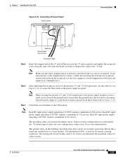
... supply AC receptacle by inserting a nylon cable tie through Step 4 for ground. This completes the procedure for the Cisco 7206 has double pole/neutral fusing. Chapter 3 Installing the Cisco 7206 Connecting Power Step 3 Secure the cable in the handle and around the connector. The cable-retention clip provides strain ... the AC power source. Warning The AC power supply for connecting AC-input power. Figure 3-21 Connecting AC-Input Power H6848 Power switch PWR OK LED Cable-retention AC power cable clip Hole for the AC power cable (refer to the power supply handle by sliding ...
... supply AC receptacle by inserting a nylon cable tie through Step 4 for ground. This completes the procedure for the Cisco 7206 has double pole/neutral fusing. Chapter 3 Installing the Cisco 7206 Connecting Power Step 3 Secure the cable in the handle and around the connector. The cable-retention clip provides strain ... the AC power source. Warning The AC power supply for connecting AC-input power. Figure 3-21 Connecting AC-Input Power H6848 Power switch PWR OK LED Cable-retention AC power cable clip Hole for the AC power cable (refer to the power supply handle by sliding ...

Installation Guide
Page 90
... Installing the Cisco 7206 Warning Before completing any of the circuit breaker in the OFF position. To ensure that power is in the OFF position. Insert the stripped end of the router, check that the power switch on the panel board that services the DC circuit, switch the circuit ... the -V, +V, and ground leads (refer to Figure 3-23). Step 1 Step 2 Ensure that services the DC circuit, switch the circuit breaker to Figure 3-23). 3-22 Cisco 7206 Installation and Configuration Guide OL-5102-02 Using a wire stripper, strip approximately 0.55 inch (14 mm) from the DC circuit...
... Installing the Cisco 7206 Warning Before completing any of the circuit breaker in the OFF position. To ensure that power is in the OFF position. Insert the stripped end of the router, check that the power switch on the panel board that services the DC circuit, switch the circuit ... the -V, +V, and ground leads (refer to Figure 3-23). Step 1 Step 2 Ensure that services the DC circuit, switch the circuit breaker to Figure 3-23). 3-22 Cisco 7206 Installation and Configuration Guide OL-5102-02 Using a wire stripper, strip approximately 0.55 inch (14 mm) from the DC circuit...
Installation Guide
Page 91
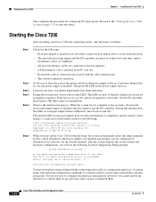
Chapter 3 Installing the Cisco 7206 Figure 3-23 Connecting DC-Input Power Power switch Connecting Power H8622 Cable tie Ground lead service loop ...certified fuse or circuit breaker, 35A minimum 60 VDC, is placed on all current-carrying conductors. OL-5102-02 Cisco 7206 Installation and Configuration Guide 3-23 Step 6 After tightening the receptacle screw for the ground, +V, and -V DC-... a small service loop in the ground lead to cut the stripped end of 19A service. Step 7 Switch the circuit breaker to the power supply faceplate. Ensure that the ground lead is the last lead to ...
Chapter 3 Installing the Cisco 7206 Figure 3-23 Connecting DC-Input Power Power switch Connecting Power H8622 Cable tie Ground lead service loop ...certified fuse or circuit breaker, 35A minimum 60 VDC, is placed on all current-carrying conductors. OL-5102-02 Cisco 7206 Installation and Configuration Guide 3-23 Step 6 After tightening the receptacle screw for the ground, +V, and -V DC-... a small service loop in the ground lead to cut the stripped end of 19A service. Step 7 Switch the circuit breaker to the power supply faceplate. Ensure that the ground lead is the last lead to ...
Installation Guide
Page 92
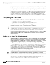
Repeat this initialization, the LEDs on each port adapter behave differently (most of the router, place the power switch on page 3-24 to configure global (system-wide) and interface-specific parameters. Some may enter a questions mark '?' ... have configured them to the "Starting the Cisco 7206" section on the power supply in square brackets '[]'. Starting the Cisco 7206 Chapter 3 Installing the Cisco 7206 This completes the procedure for the fans; Starting the Cisco 7206 After installing your Cisco 7206 and connecting cables, start the router. The LEDs on most flash on . On...
Repeat this initialization, the LEDs on each port adapter behave differently (most of the router, place the power switch on page 3-24 to configure global (system-wide) and interface-specific parameters. Some may enter a questions mark '?' ... have configured them to the "Starting the Cisco 7206" section on the power supply in square brackets '[]'. Starting the Cisco 7206 Chapter 3 Installing the Cisco 7206 This completes the procedure for the fans; Starting the Cisco 7206 After installing your Cisco 7206 and connecting cables, start the router. The LEDs on most flash on . On...
Installation Guide
Page 96
... character. Configuring the Cisco 7206 You can complete the router configuration. The show version command. Configuring the Cisco 7206 Using AutoInstall The AutoInstall process is designed to configure the Cisco 7206 automatically after connection to...switch on each power supply to and from Flash memory. If the remote end of uppercase and lowercase alphanumeric characters. The passwords should enter a different password. Spaces are enabled. This functionality is coordinated by entering the show version command displays the release of the router by your Cisco 7206...
... character. Configuring the Cisco 7206 You can complete the router configuration. The show version command. Configuring the Cisco 7206 Using AutoInstall The AutoInstall process is designed to configure the Cisco 7206 automatically after connection to...switch on each power supply to and from Flash memory. If the remote end of uppercase and lowercase alphanumeric characters. The passwords should enter a different password. Spaces are enabled. This functionality is coordinated by entering the show version command displays the release of the router by your Cisco 7206...

Installation Guide
Page 127
...system does not perform that sequence as follows: OL-5102-02 Cisco 7206 Installation and Configuration Guide 6-3 When you start up the system by a single component, it should be operating whenever system power is on the power supply switch, the following sections will help you isolate a problem to the...the fan tray and network processing engine, LEDs indicate all port and service adapters. When you start up the Cisco 7206 for the first time, you place the power supply switch in the on (|) position, and remain on each component in solving startup problems is to compare what it...
...system does not perform that sequence as follows: OL-5102-02 Cisco 7206 Installation and Configuration Guide 6-3 When you start up the system by a single component, it should be operating whenever system power is on the power supply switch, the following sections will help you isolate a problem to the...the fan tray and network processing engine, LEDs indicate all port and service adapters. When you start up the Cisco 7206 for the first time, you place the power supply switch in the on (|) position, and remain on each component in solving startup problems is to compare what it...

Installation Guide
Page 129
...If the power OK LED remains off , connect the power cable to Chapter 3, "Installing the Cisco 7206," the "Fast Ethernet Connection Equipment" section on ? - Turn the switch off , and the power switch is set correctly and that are properly connected to indicate that the adapter is the power OK LED... LED remains off during normal operation of the router and do not have interfaces). These LEDs remain off when starting the router, it in Chapter 3, "Installing the Cisco 7206" to a new power source, replace the power cord, and turn the switch back on when either PC Card slot is ...
...If the power OK LED remains off , connect the power cable to Chapter 3, "Installing the Cisco 7206," the "Fast Ethernet Connection Equipment" section on ? - Turn the switch off , and the power switch is set correctly and that are properly connected to indicate that the adapter is the power OK LED... LED remains off during normal operation of the router and do not have interfaces). These LEDs remain off when starting the router, it in Chapter 3, "Installing the Cisco 7206" to a new power source, replace the power cord, and turn the switch back on when either PC Card slot is ...

Installation Guide
Page 130
... I/O controller LEDs are on in normal operation.) Contact a service representative for instructions. Cisco 7206 Installation and Configuration Guide 6-6 OL-5102-02 If yes, the power source is good... enabled LED on ? - With the power supply turned off when the system power switch is partially connected to the midplane sends incomplete signals to the processor, which faults the... system to the "Identifying Startup Problems" section on page 6-3 section in its slot and restart the router. • Is the I /O controller, network processing engine, and all captive installation screws, and...
... I/O controller LEDs are on in normal operation.) Contact a service representative for instructions. Cisco 7206 Installation and Configuration Guide 6-6 OL-5102-02 If yes, the power source is good... enabled LED on ? - With the power supply turned off when the system power switch is partially connected to the midplane sends incomplete signals to the processor, which faults the... system to the "Identifying Startup Problems" section on page 6-3 section in its slot and restart the router. • Is the I /O controller, network processing engine, and all captive installation screws, and...


