
Installation Guide
Page 24
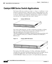
The Catalyst 4948-10GE chassis has 48 10/100/1000BASE-T Ethernet ports and two 10-Gigabit Ethernet uplink ports. They are designed for high-performance, high-density edge switching applications. Catalyst 4900 Series Switch Installation Guide 1-2 78-18039-02 Catalyst 4900 Series Switch Applications Chapter 1 Product Overview Catalyst 4900 Series Switch Applications The Catalyst 4900 series switches (see Figure 1-1, Figure 1-2, and Figure 1-3) are fixed configuration switching solutions...
The Catalyst 4948-10GE chassis has 48 10/100/1000BASE-T Ethernet ports and two 10-Gigabit Ethernet uplink ports. They are designed for high-performance, high-density edge switching applications. Catalyst 4900 Series Switch Installation Guide 1-2 78-18039-02 Catalyst 4900 Series Switch Applications Chapter 1 Product Overview Catalyst 4900 Series Switch Applications The Catalyst 4900 series switches (see Figure 1-1, Figure 1-2, and Figure 1-3) are fixed configuration switching solutions...

Installation Guide
Page 25
...Catalyst 4948 Switch Software Features Figure 1-3 Catalyst 4928-10GE Switch 271710 PS1 PS2 FAN STATUS 1 8 9 16 17 CON MGMT 24 25 26 ENABLED 27 28 Catalyst ME 4924 10GE 29 ENABLED 30 The Catalyst 4928-10GE switch has a 48-Gbps, nonblocking, full-duplex switching fabric, providing 102 million packets-per-second of Catalyst 4948...IDs - IEEE 802.1Q VLAN tagging on all ports - Catalyst 4948 Switch Software Features The following is an overview of switching capacity for EFM - Cisco Inter Switch Link (ISL) tagging on all ports • 16,000 multicast forwarding entries and 16...
...Catalyst 4948 Switch Software Features Figure 1-3 Catalyst 4928-10GE Switch 271710 PS1 PS2 FAN STATUS 1 8 9 16 17 CON MGMT 24 25 26 ENABLED 27 28 Catalyst ME 4924 10GE 29 ENABLED 30 The Catalyst 4928-10GE switch has a 48-Gbps, nonblocking, full-duplex switching fabric, providing 102 million packets-per-second of Catalyst 4948...IDs - IEEE 802.1Q VLAN tagging on all ports - Catalyst 4948 Switch Software Features The following is an overview of switching capacity for EFM - Cisco Inter Switch Link (ISL) tagging on all ports • 16,000 multicast forwarding entries and 16...
Installation Guide
Page 28
...-X - IEEE 802.3ae - IEEE 802.3ab 1000BASE-T - The following standards are high-performance dedicated Ethernet switches that fully integrate into the Catalyst family of the Catalyst 4900 series hardware features: • (Catalyst 4948 and 4948-10GE) 48 10BASE-T/100BASE-TX/1000BASE-T Ethernet ports using an RJ-45 interface • A removable automatic variable speed fan tray for low noise (no...
...-X - IEEE 802.3ae - IEEE 802.3ab 1000BASE-T - The following standards are high-performance dedicated Ethernet switches that fully integrate into the Catalyst family of the Catalyst 4900 series hardware features: • (Catalyst 4948 and 4948-10GE) 48 10BASE-T/100BASE-TX/1000BASE-T Ethernet ports using an RJ-45 interface • A removable automatic variable speed fan tray for low noise (no...
Installation Guide
Page 29
...-18039-02 Catalyst 4900 Series Switch Installation Guide 1-7 Figure 1-4 and Figure 1-5 show the location of the management and console ports on the Catalyst 4948-10GE There are 28 1000BASE-X Ethernet ports using X2 interfaces. These SFP ports share MAC addresses with the last four 10/100/1000BASE-T ports. The default is supported on the Catalyst 4928-10GE There are 48 10/100...
...-18039-02 Catalyst 4900 Series Switch Installation Guide 1-7 Figure 1-4 and Figure 1-5 show the location of the management and console ports on the Catalyst 4948-10GE There are 28 1000BASE-X Ethernet ports using X2 interfaces. These SFP ports share MAC addresses with the last four 10/100/1000BASE-T ports. The default is supported on the Catalyst 4928-10GE There are 48 10/100...
Installation Guide
Page 32
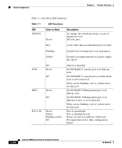
...rommon mode or a power supply has failed CON MGT Port 1-48 Off Green Off Green Off Green Yellow Flashing yellow Off Switch is disabled 10/100 BASE-T console port is in link-up state 10/100 BASE-T console port is in link-down state or not connected There are ... are no blinking, red, or yellow states for this port Port is operational Port is disabled by user Power-on self-test indicates faulty port No signal detected or link configuration failure 1-10 Catalyst 4900 Series Switch Installation Guide 78-18039-02 Switch Components Chapter 1 Product Overview Table 1-1 describes LED functions....
...rommon mode or a power supply has failed CON MGT Port 1-48 Off Green Off Green Off Green Yellow Flashing yellow Off Switch is disabled 10/100 BASE-T console port is in link-up state 10/100 BASE-T console port is in link-down state or not connected There are ... are no blinking, red, or yellow states for this port Port is operational Port is disabled by user Power-on self-test indicates faulty port No signal detected or link configuration failure 1-10 Catalyst 4900 Series Switch Installation Guide 78-18039-02 Switch Components Chapter 1 Product Overview Table 1-1 describes LED functions....
Installation Guide
Page 62
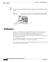
... Ethernet Transceiver Modules Compatibility Matrix at the following location: http://www.cisco.com/en/US/products/hw/modules/ps5455/products_device_sup port_table09186a00803857e7.html Catalyst 4900 Series Switch Installation Guide 4-2 78-18039-02 X2 Modules Chapter 4 Transceiver Modules...cisco.com/en/US/products/hw/modules/ps5455/prod_installation_gu ide09186a00803469ed.html For compatibility information, refer to the SFP Module (Catalyst 4948) Catalyst 4948 113146 CON AUX 45 46 47 48 X2 Modules You must insert the SFP with the latching mechanism reversed on SFP port 46 and port 48...
... Ethernet Transceiver Modules Compatibility Matrix at the following location: http://www.cisco.com/en/US/products/hw/modules/ps5455/products_device_sup port_table09186a00803857e7.html Catalyst 4900 Series Switch Installation Guide 4-2 78-18039-02 X2 Modules Chapter 4 Transceiver Modules...cisco.com/en/US/products/hw/modules/ps5455/prod_installation_gu ide09186a00803469ed.html For compatibility information, refer to the SFP Module (Catalyst 4948) Catalyst 4948 113146 CON AUX 45 46 47 48 X2 Modules You must insert the SFP with the latching mechanism reversed on SFP port 46 and port 48...
Installation Guide
Page 73
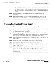
...the Installation Troubleshooting the Power Supply Step 3 Step 4 • The port LEDs (1-48) are unable to resolve the problem, contact a customer service representative for instructions. The port LED remains yellow if the port is the first power source. If the boot information and system banner... 4 Step 5 Step 6 Step 7 Verify that the power supply is red, contact a customer service representative for instructions. 78-18039-02 Catalyst 4900 Series Switch Installation Guide 5-5 Look at startup. If the LED remains off, there might be a problem with a new power cord, the power supply...
...the Installation Troubleshooting the Power Supply Step 3 Step 4 • The port LEDs (1-48) are unable to resolve the problem, contact a customer service representative for instructions. The port LED remains yellow if the port is the first power source. If the boot information and system banner... 4 Step 5 Step 6 Step 7 Verify that the power supply is red, contact a customer service representative for instructions. 78-18039-02 Catalyst 4900 Series Switch Installation Guide 5-5 Look at startup. If the LED remains off, there might be a problem with a new power cord, the power supply...
Installation Guide
Page 80
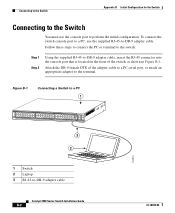
...switch console port to a PC, use the console port to -DB-9 adapter cable Catalyst 4900 Series Switch Installation Guide B-2 78-18039-02 Attach the DB-9 female DTE of the switch, as shown in Figure B-1. Figure B-1 Connecting a Switch to a PC 1 PS1 PS2 FAN STATUS 1 16 17 32 33 Catalyst 4948 CON 48 MGT 45 46 47 48 3 2 181874 1 Switch... 2 Laptop 3 RJ-45-to perform the initial configuration. Connecting to the Switch Appendix B Initial Configuration for the Switch Connecting to the Switch You must use the ...
...switch console port to a PC, use the console port to -DB-9 adapter cable Catalyst 4900 Series Switch Installation Guide B-2 78-18039-02 Attach the DB-9 female DTE of the switch, as shown in Figure B-1. Figure B-1 Connecting a Switch to a PC 1 PS1 PS2 FAN STATUS 1 16 17 32 33 Catalyst 4948 CON 48 MGT 45 46 47 48 3 2 181874 1 Switch... 2 Laptop 3 RJ-45-to perform the initial configuration. Connecting to the Switch Appendix B Initial Configuration for the Switch Connecting to the Switch You must use the ...


