

Installation Guide
Page 5
... xxi Product Overview 1-1 Catalyst 4900 Series Switch Applications 1-2 Catalyst 4948 Switch Software Features 1-3 Catalyst 4948-10GE and Catalyst 4928-10GE Switch Software Features 1-4 Hardware System Features 1-6 Switch Components 1-7 Traffic Ports on the Catalyst 4948 1-7 Traffic Ports on the Catalyst 4948-10GE 1-7 Traffic Ports on the Catalyst 4928-10GE 1-7 Console Port 1-7 Front Panel LEDs 1-9 Chassis Cooling 1-11 Power Supplies 1-12 Environmental Monitoring of the Power Supplies 1-13 Power Management for the Switch 1-14 Power Management Modes 1-14...
... xxi Product Overview 1-1 Catalyst 4900 Series Switch Applications 1-2 Catalyst 4948 Switch Software Features 1-3 Catalyst 4948-10GE and Catalyst 4928-10GE Switch Software Features 1-4 Hardware System Features 1-6 Switch Components 1-7 Traffic Ports on the Catalyst 4948 1-7 Traffic Ports on the Catalyst 4948-10GE 1-7 Traffic Ports on the Catalyst 4928-10GE 1-7 Console Port 1-7 Front Panel LEDs 1-9 Chassis Cooling 1-11 Power Supplies 1-12 Environmental Monitoring of the Power Supplies 1-13 Power Management for the Switch 1-14 Power Management Modes 1-14...
Installation Guide
Page 6
... the Fiber-Optic Connectors 4-5 Additional Guidelines 4-7 Troubleshooting the Installation 5-1 Getting Started 5-2 Problem Solving to the System Component Level 5-2 Identifying Startup Problems 5-3 LED Readings 5-3 Troubleshooting the Power Supply 5-5 Contacting Customer Service 5-6 Specifications A-1 Console Port A-1 Catalyst 4900 Series Switch Installation Guide vi 78-18039-02
... the Fiber-Optic Connectors 4-5 Additional Guidelines 4-7 Troubleshooting the Installation 5-1 Getting Started 5-2 Problem Solving to the System Component Level 5-2 Identifying Startup Problems 5-3 LED Readings 5-3 Troubleshooting the Power Supply 5-5 Contacting Customer Service 5-6 Specifications A-1 Console Port A-1 Catalyst 4900 Series Switch Installation Guide vi 78-18039-02
Installation Guide
Page 24
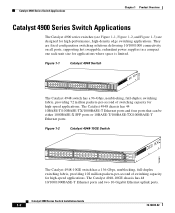
... applications where space is limited. Figure 1-2 Catalyst 4948-10GE Switch 130083 PS1 PS2 FAN STATUS 1 16 17 32 33 Catalyst WS-C4948 10GE X2-1 X2-2 CON 48 MGT The Catalyst 4948-10GE switch has a 136-Gbps, nonblocking, full-duplex switching fabric, providing 102 million packets-per -second of switching capacity for high-speed applications. The Catalyst 4948 chassis has 44 10BASE-T/100BASE-TX/1000BASE...
... applications where space is limited. Figure 1-2 Catalyst 4948-10GE Switch 130083 PS1 PS2 FAN STATUS 1 16 17 32 33 Catalyst WS-C4948 10GE X2-1 X2-2 CON 48 MGT The Catalyst 4948-10GE switch has a 136-Gbps, nonblocking, full-duplex switching fabric, providing 102 million packets-per -second of switching capacity for high-speed applications. The Catalyst 4948 chassis has 44 10BASE-T/100BASE-TX/1000BASE...

Installation Guide
Page 25
... Switch Installation Guide 1-3 The Catalyst 4928-10GE chassis has 28 1000BASEX SFP ports, and two X2 10-Gigabit Ethernet uplink ports. Cisco Inter Switch Link (ISL) tagging on all ports - All three switches have a removable automatic variable speed fan tray for low noise operation at room temperature and removable and redundant 300 W AC or 300 W DC power supply...
... Switch Installation Guide 1-3 The Catalyst 4928-10GE chassis has 28 1000BASEX SFP ports, and two X2 10-Gigabit Ethernet uplink ports. Cisco Inter Switch Link (ISL) tagging on all ports - All three switches have a removable automatic variable speed fan tray for low noise operation at room temperature and removable and redundant 300 W AC or 300 W DC power supply...
Installation Guide
Page 28
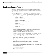
... W DC power supplies • 256-MB SDRAM (fixed), 64-MB embedded Flash memory • EtherChannel at 10/100/1000 Mbps (and 10 Gbps for the Catalyst 4948-10GE and Catalyst 4928-10GE) • Hardware-based access lists • Storm control in hardware Catalyst 4900 Series Switch Installation Guide... 1-6 78-18039-02 IEEE 802.1Q - IEEE 802.1p • (Catalyst 4948) Four 1000BASE-X Ethernet ports using SFP...
... W DC power supplies • 256-MB SDRAM (fixed), 64-MB embedded Flash memory • EtherChannel at 10/100/1000 Mbps (and 10 Gbps for the Catalyst 4948-10GE and Catalyst 4928-10GE) • Hardware-based access lists • Storm control in hardware Catalyst 4900 Series Switch Installation Guide... 1-6 78-18039-02 IEEE 802.1Q - IEEE 802.1p • (Catalyst 4948) Four 1000BASE-X Ethernet ports using SFP...
Installation Guide
Page 31
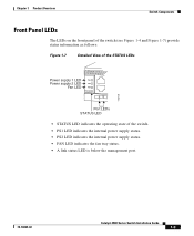
... LEDs STATUS LED • STATUS LED indicates the operating state of the switch. • PS1 LED indicates the internal power supply status. • PS2 LED indicates the internal power supply status. • FAN LED indicates the fan tray status. • A link status LED is below the management port. 78-18039-02 Catalyst 4900 Series Switch Installation Guide 1-9
... LEDs STATUS LED • STATUS LED indicates the operating state of the switch. • PS1 LED indicates the internal power supply status. • PS2 LED indicates the internal power supply status. • FAN LED indicates the fan tray status. • A link status LED is below the management port. 78-18039-02 Catalyst 4900 Series Switch Installation Guide 1-9
Installation Guide
Page 32
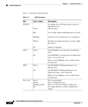
... test fails Flashing System boot or diagnostic tests in progress Yellow System is in rommon mode or a power supply has failed CON MGT Port 1-48 Off Green Off Green Off Green Yellow Flashing yellow Off Switch is disabled 10/100 BASE-T console port is in link-up state 10/100 BASE-T console port... link-down state or not connected There are no blinking, red, or yellow states for this port Port is operational Port is disabled by user Power-on self-test indicates faulty port No signal detected or link configuration failure 1-10 Catalyst 4900 Series Switch Installation Guide 78-18039-02
... test fails Flashing System boot or diagnostic tests in progress Yellow System is in rommon mode or a power supply has failed CON MGT Port 1-48 Off Green Off Green Off Green Yellow Flashing yellow Off Switch is disabled 10/100 BASE-T console port is in link-up state 10/100 BASE-T console port... link-down state or not connected There are no blinking, red, or yellow states for this port Port is operational Port is disabled by user Power-on self-test indicates faulty port No signal detected or link configuration failure 1-10 Catalyst 4900 Series Switch Installation Guide 78-18039-02
Installation Guide
Page 33
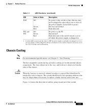
... Fault detected or the on or it is red, the supply is either LED is green and the other is OFF the power supply is drawn in 1. If either plugged in and not switched on /off while the power supply is plugged in from the sides of the switch. 78-18039-02 Catalyst 4900 Series Switch Installation Guide 1-11
... Fault detected or the on or it is red, the supply is either LED is green and the other is OFF the power supply is drawn in 1. If either plugged in and not switched on /off while the power supply is plugged in from the sides of the switch. 78-18039-02 Catalyst 4900 Series Switch Installation Guide 1-11
Installation Guide
Page 34
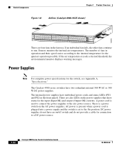
... other fans continue to the On position. DC power supplies do not have an on/off switch and do not provide a cable for the quietest operation possible. 130085 Switch Components Chapter 1 Product Overview Figure 1-8 Airflow (Catalyst 4948-10GE shown) PS1 PS2 FAN STATUS 1 16 17 32 33 Catalyst WS-C4948 10GE X2-1 X2-2 CON 48 MGT There are also...
... other fans continue to the On position. DC power supplies do not have an on/off switch and do not provide a cable for the quietest operation possible. 130085 Switch Components Chapter 1 Product Overview Figure 1-8 Airflow (Catalyst 4948-10GE shown) PS1 PS2 FAN STATUS 1 16 17 32 33 Catalyst WS-C4948 10GE X2-1 X2-2 CON 48 MGT There are also...
Installation Guide
Page 35
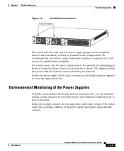
... used, you must use the blank faceplate supplied to cover the empty power bay. If only one power supply plugged in this configuration. Environmental Monitoring of the power supply and reports status through software. 78-18039-02 Catalyst 4900 Series Switch Installation Guide 1-13 The switch senses the operating condition of the Power Supplies Using the environmental monitoring and reporting functions...
... used, you must use the blank faceplate supplied to cover the empty power bay. If only one power supply plugged in this configuration. Environmental Monitoring of the power supply and reports status through software. 78-18039-02 Catalyst 4900 Series Switch Installation Guide 1-13 The switch senses the operating condition of the Power Supplies Using the environmental monitoring and reporting functions...
Installation Guide
Page 36
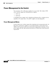
... status. Power Management Modes Catalyst 4900 series switches support the redundant power management mode. If one power supply fails, the other unit increases power to 45/55 percent of the total system power requirements at all times. The Catalyst 4900 series switches support the following power supplies: • 300 W AC • 300 W DC A redundant power supply can choose AC or DC power supplies for the Switch You...
... status. Power Management Modes Catalyst 4900 series switches support the redundant power management mode. If one power supply fails, the other unit increases power to 45/55 percent of the total system power requirements at all times. The Catalyst 4900 series switches support the following power supplies: • 300 W AC • 300 W DC A redundant power supply can choose AC or DC power supplies for the Switch You...
Installation Guide
Page 41
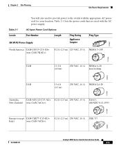
... that are used with the appropriate AC power cord for your location. Chapter 2 Site Planning Site Power Requirements You will also need to provide power to the switch with the AC power supply. Table 2-1 AC-Input Power Cord Options Locale Part Number 300 W AC Power Supply Length Plug Rating Appliance Coupler Plug Type 120352 North America CAB-US515-C15...-7ACA=) AS/NZS 3112-1993 120356 Europe (except CAB-CEE77-C15-EU= 8.2 ft (2.5 m) 250 VAC, 16 A CEE 7/7 Italy) (was CAB-7ACE=) 120357 78-18039-02 Catalyst 4900 Series Switch Installation Guide 2-5
... that are used with the appropriate AC power cord for your location. Chapter 2 Site Planning Site Power Requirements You will also need to provide power to the switch with the AC power supply. Table 2-1 AC-Input Power Cord Options Locale Part Number 300 W AC Power Supply Length Plug Rating Appliance Coupler Plug Type 120352 North America CAB-US515-C15...-7ACA=) AS/NZS 3112-1993 120356 Europe (except CAB-CEE77-C15-EU= 8.2 ft (2.5 m) 250 VAC, 16 A CEE 7/7 Italy) (was CAB-7ACE=) 120357 78-18039-02 Catalyst 4900 Series Switch Installation Guide 2-5
Installation Guide
Page 44
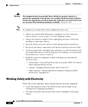
... equipment in the chassis. See the "Lifting the Chassis Safely" section on page 3-5 before lifting the switch. • Always turn all power supplies off by unplugging all power and external cables before installing or removing a chassis. • Keep the chassis area clear and free ... Part I, CSA C22.1 - Statement 1024 Note To completely de-energize the system, unplug the power cord. • Always use caution when lifting heavy equipment. Catalyst 4900 Series Switch Installation Guide 2-8 78-18039-02 Contact the appropriate electrical inspection authority or an electrician if you ...
... equipment in the chassis. See the "Lifting the Chassis Safely" section on page 3-5 before lifting the switch. • Always turn all power supplies off by unplugging all power and external cables before installing or removing a chassis. • Keep the chassis area clear and free ... Part I, CSA C22.1 - Statement 1024 Note To completely de-energize the system, unplug the power cord. • Always use caution when lifting heavy equipment. Catalyst 4900 Series Switch Installation Guide 2-8 78-18039-02 Contact the appropriate electrical inspection authority or an electrician if you ...
Installation Guide
Page 46
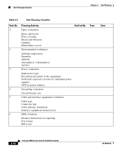
... proximity to the equipment Dedicated (separate) circuits for redundant power supplies UPS for power failures 4 Grounding evaluation: Circuit breaker size 5 Cable and interface equipment evaluation: Cable type Connector type Cable distance limitations Interface equipment (transceivers) 6 EMI evaluation: Distance limitations for signaling Site wiring RFI levels 2-10 Catalyst 4900 Series Switch Installation Guide 78-18039-02
... proximity to the equipment Dedicated (separate) circuits for redundant power supplies UPS for power failures 4 Grounding evaluation: Circuit breaker size 5 Cable and interface equipment evaluation: Cable type Connector type Cable distance limitations Interface equipment (transceivers) 6 EMI evaluation: Distance limitations for signaling Site wiring RFI levels 2-10 Catalyst 4900 Series Switch Installation Guide 78-18039-02
Installation Guide
Page 50
...least 3 to 4 feet (91.4 to avoid disconnecting cables unnecessarily for equipment maintenance or upgrades. - Use baffles correctly to the power supplies or switching modules. Note that a ventilation system in a closed rack that is installed in the rack. Note that equipment near the top of... the rack (if the rack is provided with the rack open rack whenever possible. - Catalyst 4900 Series Switch Installation Guide 3-4 78-18039-02 Rack-Mounting the Switch Chapter 3 Installing the Switch - Route cables away from the chassis intake vent. If necessary, operate the chassis with...
...least 3 to 4 feet (91.4 to avoid disconnecting cables unnecessarily for equipment maintenance or upgrades. - Use baffles correctly to the power supplies or switching modules. Note that a ventilation system in a closed rack that is installed in the rack. Note that equipment near the top of... the rack (if the rack is provided with the rack open rack whenever possible. - Catalyst 4900 Series Switch Installation Guide 3-4 78-18039-02 Rack-Mounting the Switch Chapter 3 Installing the Switch - Route cables away from the chassis intake vent. If necessary, operate the chassis with...

Installation Guide
Page 55
... the main disconnecting device. Statement 1019 Step 2 Plug the power cords into the power supplies. (Figure 3-6 shows plug locations.) 78-18039-02 Catalyst 4900 Series Switch Installation Guide 3-9 Proceed to the "Connecting AC Power to the Switch" section on page 2-6. Warning The plug-socket combination must... Installing the Switch Connecting AC Power to the Switch Figure 3-4 Installing the Cable Guide 130089 PS1 PS2 FAN STATUS 1 16 17 32 33 Catalyst WS-C4948 10GE X2-1 X2-2 CON 48 MGT Step 5 Do not connect the power cord at all of the site power and grounding ...
... the main disconnecting device. Statement 1019 Step 2 Plug the power cords into the power supplies. (Figure 3-6 shows plug locations.) 78-18039-02 Catalyst 4900 Series Switch Installation Guide 3-9 Proceed to the "Connecting AC Power to the Switch" section on page 2-6. Warning The plug-socket combination must... Installing the Switch Connecting AC Power to the Switch Figure 3-4 Installing the Cable Guide 130089 PS1 PS2 FAN STATUS 1 16 17 32 33 Catalyst WS-C4948 10GE X2-1 X2-2 CON 48 MGT Step 5 Do not connect the power cord at all of the site power and grounding ...
Installation Guide
Page 56
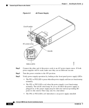
... source. The on different circuits. If both power supplies will be used, make sure they are functioning normally. • The PS1 or PS2 LED is red when the power supply is no power supply installed. 3-10 Catalyst 4900 Series Switch Installation Guide 78-18039-02 Connecting AC Power to the Switch Figure 3-5 AC Power Supply On/off when there is not functioning...
... source. The on different circuits. If both power supplies will be used, make sure they are functioning normally. • The PS1 or PS2 LED is red when the power supply is no power supply installed. 3-10 Catalyst 4900 Series Switch Installation Guide 78-18039-02 Connecting AC Power to the Switch Figure 3-5 AC Power Supply On/off when there is not functioning...
Installation Guide
Page 57
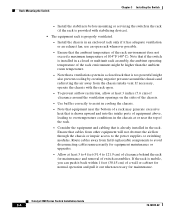
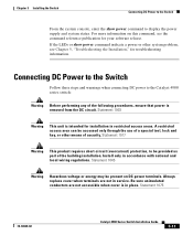
... or show power command to display the power supply and system status. Statement 1045 Warning Hazardous voltage or energy may be present on this command, see Chapter 5, "Troubleshooting the Installation," for troubleshooting information. Statement 1003 Warning This unit is intended for installation in service. Statement 1075 78-18039-02 Catalyst 4900 Series Switch Installation Guide...
... or show power command to display the power supply and system status. Statement 1045 Warning Hazardous voltage or energy may be present on this command, see Chapter 5, "Troubleshooting the Installation," for troubleshooting information. Statement 1003 Warning This unit is intended for installation in service. Statement 1075 78-18039-02 Catalyst 4900 Series Switch Installation Guide...
Installation Guide
Page 58
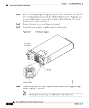
... #12 wire. 3-12 Catalyst 4900 Series Switch Installation Guide 78-18039-02 Figure 3-6 DC Power Supply DC input terminals Handle 120697 Status LEDs Step 4 Connect the positive and negative power cables into the power supplies using a number 2 Phillips screwdriver. Note The DC power cables may use AWG #10 to earth ground. Connecting DC Power to the Switch Chapter 3 Installing the...
... #12 wire. 3-12 Catalyst 4900 Series Switch Installation Guide 78-18039-02 Figure 3-6 DC Power Supply DC input terminals Handle 120697 Status LEDs Step 4 Connect the positive and negative power cables into the power supplies using a number 2 Phillips screwdriver. Note The DC power cables may use AWG #10 to earth ground. Connecting DC Power to the Switch Chapter 3 Installing the...
Installation Guide
Page 59
... LEDs or show power command to an DC-power input source. Connect the other system problem, see the command reference publication for troubleshooting information. 78-18039-02 Catalyst 4900 Series Switch Installation Guide 3-13 From the system console, enter the show power command indicate a power or other end of the power cables to display the power supply and system...
... LEDs or show power command to an DC-power input source. Connect the other system problem, see the command reference publication for troubleshooting information. 78-18039-02 Catalyst 4900 Series Switch Installation Guide 3-13 From the system console, enter the show power command indicate a power or other end of the power cables to display the power supply and system...

