

Installation Guide
Page 5
... Product Overview 1-1 Catalyst 4900 Series Switch Applications 1-2 Catalyst 4948 Switch Software Features 1-3 Catalyst 4948-10GE and Catalyst 4928-10GE Switch Software Features 1-4 Hardware System Features 1-6 Switch Components 1-7 Traffic Ports on the Catalyst 4948 1-7 Traffic Ports on the Catalyst 4948-10GE 1-7 Traffic Ports on the Catalyst 4928-10GE 1-7 Console Port 1-7 Front Panel LEDs 1-9 Chassis Cooling 1-11 Power Supplies 1-12 Environmental Monitoring of the Power Supplies 1-13 Power Management for the Switch 1-14 Power Management Modes...
... Product Overview 1-1 Catalyst 4900 Series Switch Applications 1-2 Catalyst 4948 Switch Software Features 1-3 Catalyst 4948-10GE and Catalyst 4928-10GE Switch Software Features 1-4 Hardware System Features 1-6 Switch Components 1-7 Traffic Ports on the Catalyst 4948 1-7 Traffic Ports on the Catalyst 4948-10GE 1-7 Traffic Ports on the Catalyst 4928-10GE 1-7 Console Port 1-7 Front Panel LEDs 1-9 Chassis Cooling 1-11 Power Supplies 1-12 Environmental Monitoring of the Power Supplies 1-13 Power Management for the Switch 1-14 Power Management Modes...
Installation Guide
Page 6
... the Fiber-Optic Connectors 4-5 Additional Guidelines 4-7 Troubleshooting the Installation 5-1 Getting Started 5-2 Problem Solving to the System Component Level 5-2 Identifying Startup Problems 5-3 LED Readings 5-3 Troubleshooting the Power Supply 5-5 Contacting Customer Service 5-6 Specifications A-1 Console Port A-1 Catalyst 4900 Series Switch Installation Guide vi 78-18039-02
... the Fiber-Optic Connectors 4-5 Additional Guidelines 4-7 Troubleshooting the Installation 5-1 Getting Started 5-2 Problem Solving to the System Component Level 5-2 Identifying Startup Problems 5-3 LED Readings 5-3 Troubleshooting the Power Supply 5-5 Contacting Customer Service 5-6 Specifications A-1 Console Port A-1 Catalyst 4900 Series Switch Installation Guide vi 78-18039-02
Installation Guide
Page 7
B A P P E N D I X C A P P E N D I X Management Port A-2 Catalyst 4900 Series Switch Specifications A-3 Initial Configuration for the Switch B-1 Connecting to the Switch B-2 Starting the Terminal-Emulation Software B-3 Connecting to a Power Source B-3 Entering the Initial Configuration Information B-4 IP Settings B-4 Performing the Initial Configuration B-5 Compliance Information and Translated Safety Warnings C-1 Translated Safety Warnings C-2 Statement 1003-DC Power Disconnection C-2 Statement 1004-Installation Instructions C-4 Statement 1006-Chassis...
B A P P E N D I X C A P P E N D I X Management Port A-2 Catalyst 4900 Series Switch Specifications A-3 Initial Configuration for the Switch B-1 Connecting to the Switch B-2 Starting the Terminal-Emulation Software B-3 Connecting to a Power Source B-3 Entering the Initial Configuration Information B-4 IP Settings B-4 Performing the Initial Configuration B-5 Compliance Information and Translated Safety Warnings C-1 Translated Safety Warnings C-2 Statement 1003-DC Power Disconnection C-2 Statement 1004-Installation Instructions C-4 Statement 1006-Chassis...
Installation Guide
Page 8
INDEX Statement 191-VCCI Class A Warning for Japan C-50 Statement 256-Class A Warning for Hungary C-51 Statement 294-Class A Warning for Korea C-51 Statement 257-Class A Notice for Taiwan and Other Traditional Chinese Markets C-52 Statement 371-Power Cable and AC Adapter C-52 Catalyst 4900 Series Switch Installation Guide viii 78-18039-02
INDEX Statement 191-VCCI Class A Warning for Japan C-50 Statement 256-Class A Warning for Hungary C-51 Statement 294-Class A Warning for Korea C-51 Statement 257-Class A Notice for Taiwan and Other Traditional Chinese Markets C-52 Statement 371-Power Cable and AC Adapter C-52 Catalyst 4900 Series Switch Installation Guide viii 78-18039-02
Installation Guide
Page 24
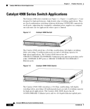
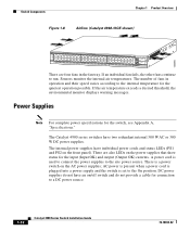
... all ports, supporting hot swappable, redundant power supplies in a compact one rack-unit size for high-performance, high-density edge switching applications. Figure 1-2 Catalyst 4948-10GE Switch 130083 PS1 PS2 FAN STATUS 1 16 17 32 33 Catalyst WS-C4948 10GE X2-1 X2-2 CON 48 MGT The Catalyst 4948-10GE switch has a 136-Gbps, nonblocking, full-duplex switching fabric, providing 102 million packets-per...
... all ports, supporting hot swappable, redundant power supplies in a compact one rack-unit size for high-performance, high-density edge switching applications. Figure 1-2 Catalyst 4948-10GE Switch 130083 PS1 PS2 FAN STATUS 1 16 17 32 33 Catalyst WS-C4948 10GE X2-1 X2-2 CON 48 MGT The Catalyst 4948-10GE switch has a 136-Gbps, nonblocking, full-duplex switching fabric, providing 102 million packets-per...

Installation Guide
Page 25
... 78-18039-02 Catalyst 4900 Series Switch Installation Guide 1-3 Cisco Inter Switch Link (ISL) tagging on all ports - All three switches have a removable automatic variable speed fan tray for low noise operation at room temperature and removable and redundant 300 W AC or 300 W DC power supply provides fault-tolerance protection for the switch. The Catalyst 4928-10GE chassis has...
... 78-18039-02 Catalyst 4900 Series Switch Installation Guide 1-3 Cisco Inter Switch Link (ISL) tagging on all ports - All three switches have a removable automatic variable speed fan tray for low noise operation at room temperature and removable and redundant 300 W AC or 300 W DC power supply provides fault-tolerance protection for the switch. The Catalyst 4928-10GE chassis has...
Installation Guide
Page 28
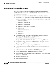
...and/or Full Duplex - The following standards are high-performance dedicated Ethernet switches that fully integrate into the Catalyst family of the Catalyst 4900 series hardware features: • (Catalyst 4948 and 4948-10GE) 48 10BASE-T/100BASE-TX/1000BASE-T Ethernet ports using RJ-45 interfaces.... DC power supplies • 256-MB SDRAM (fixed), 64-MB embedded Flash memory • EtherChannel at 10/100/1000 Mbps (and 10 Gbps for the Catalyst 4948-10GE and Catalyst 4928-10GE) • Hardware-based access lists • Storm control in hardware Catalyst 4900 Series Switch Installation ...
...and/or Full Duplex - The following standards are high-performance dedicated Ethernet switches that fully integrate into the Catalyst family of the Catalyst 4900 series hardware features: • (Catalyst 4948 and 4948-10GE) 48 10BASE-T/100BASE-TX/1000BASE-T Ethernet ports using RJ-45 interfaces.... DC power supplies • 256-MB SDRAM (fixed), 64-MB embedded Flash memory • EtherChannel at 10/100/1000 Mbps (and 10 Gbps for the Catalyst 4948-10GE and Catalyst 4928-10GE) • Hardware-based access lists • Storm control in hardware Catalyst 4900 Series Switch Installation ...
Installation Guide
Page 31
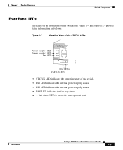
... Front Panel LEDs The LEDs on the front panel of the switch (see Figure 1-4 and Figure 1-7) provide status information as follows: Figure 1-7 Detailed View of the STATUS LEDs 113141 Power supply 1 LED Power supply 2 LED Fan LED PS1 PS2 FAN STATUS 1 Port LEDs STATUS LED • STATUS LED... indicates the operating state of the switch. • PS1 LED indicates the internal power supply status. • PS2 LED indicates the internal power supply status. • FAN LED indicates the fan tray status. • A link status LED ...
... Front Panel LEDs The LEDs on the front panel of the switch (see Figure 1-4 and Figure 1-7) provide status information as follows: Figure 1-7 Detailed View of the STATUS LEDs 113141 Power supply 1 LED Power supply 2 LED Fan LED PS1 PS2 FAN STATUS 1 Port LEDs STATUS LED • STATUS LED... indicates the operating state of the switch. • PS1 LED indicates the internal power supply status. • PS2 LED indicates the internal power supply status. • FAN LED indicates the fan tray status. • A link status LED ...
Installation Guide
Page 32
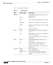
... functions. Table 1-1 LED Functions LED STATUS Color or State Green Description At startup, the switch performs a series of diagnostic tests: All tests pass Red A test other than an individual...progress Yellow System is in rommon mode or a power supply has failed CON MGT Port 1-48 Off Green Off Green Off Green Yellow Flashing yellow Off Switch is disabled 10/100 BASE-T console port is... Port is operational Port is disabled by user Power-on self-test indicates faulty port No signal detected or link configuration failure 1-10 Catalyst 4900 Series Switch Installation Guide 78-18039-02
... functions. Table 1-1 LED Functions LED STATUS Color or State Green Description At startup, the switch performs a series of diagnostic tests: All tests pass Red A test other than an individual...progress Yellow System is in rommon mode or a power supply has failed CON MGT Port 1-48 Off Green Off Green Off Green Yellow Flashing yellow Off Switch is disabled 10/100 BASE-T console port is... Port is operational Port is disabled by user Power-on self-test indicates faulty port No signal detected or link configuration failure 1-10 Catalyst 4900 Series Switch Installation Guide 78-18039-02
Installation Guide
Page 33
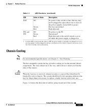
Chassis Cooling Note For environmental specifications, see Chapter 2, "Site Planning." If either plugged in and not switched on /off switch is set to off while the power supply is faulty. It may not be plugged in . If it is plugged in 1. Caution When the fan tray is removed, internal circuitry is exposed ... if one . The system should not be touched by tools or fingers. Figure 1-8 shows the direction of airflow going in from the sides of the switch. 78-18039-02 Catalyst 4900 Series Switch Installation Guide 1-11
Chassis Cooling Note For environmental specifications, see Chapter 2, "Site Planning." If either plugged in and not switched on /off switch is set to off while the power supply is faulty. It may not be plugged in . If it is plugged in 1. Caution When the fan tray is removed, internal circuitry is exposed ... if one . The system should not be touched by tools or fingers. Figure 1-8 shows the direction of airflow going in from the sides of the switch. 78-18039-02 Catalyst 4900 Series Switch Installation Guide 1-11
Installation Guide
Page 34
.... There is set to a DC power source. 1-12 Catalyst 4900 Series Switch Installation Guide 78-18039-02 The internal power supplies have individual power cords and status LEDs (PS1 and PS2 on the power supplies that show status for connection to the On position. 130085 Switch Components Chapter 1 Product Overview Figure 1-8 Airflow (Catalyst 4948-10GE shown) PS1 PS2 FAN STATUS...
.... There is set to a DC power source. 1-12 Catalyst 4900 Series Switch Installation Guide 78-18039-02 The internal power supplies have individual power cords and status LEDs (PS1 and PS2 on the power supplies that show status for connection to the On position. 130085 Switch Components Chapter 1 Product Overview Figure 1-8 Airflow (Catalyst 4948-10GE shown) PS1 PS2 FAN STATUS...
Installation Guide
Page 35
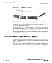
...We recommend that you always connect both power supplies to loss of the power supply and reports status through software. 78-18039-02 Catalyst 4900 Series Switch Installation Guide 1-13 For safety reasons, the AC power supply needs to be switched off from a chassis or inserted ...into a chassis. Chapter 1 Product Overview Figure 1-9 On/Off Switch Locations On/Off Switch Switch Components 113143 The switch will start with only one power ...
...We recommend that you always connect both power supplies to loss of the power supply and reports status through software. 78-18039-02 Catalyst 4900 Series Switch Installation Guide 1-13 For safety reasons, the AC power supply needs to be switched off from a chassis or inserted ...into a chassis. Chapter 1 Product Overview Figure 1-9 On/Off Switch Locations On/Off Switch Switch Components 113143 The switch will start with only one power ...
Installation Guide
Page 36
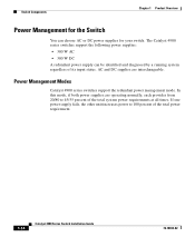
... system power requirements at all times. Power Management Modes Catalyst 4900 series switches support the redundant power management mode. Switch Components Chapter 1 Product Overview Power Management for the Switch You can be identified and diagnosed by a running system regardless of the total power requirement. 1-14 Catalyst 4900 Series Switch Installation Guide 78-18039-02 The Catalyst 4900 series switches support the following power supplies...
... system power requirements at all times. Power Management Modes Catalyst 4900 series switches support the redundant power management mode. Switch Components Chapter 1 Product Overview Power Management for the Switch You can be identified and diagnosed by a running system regardless of the total power requirement. 1-14 Catalyst 4900 Series Switch Installation Guide 78-18039-02 The Catalyst 4900 series switches support the following power supplies...

Installation Guide
Page 37
... an enclosed, secure area, ensuring that only qualified personnel have access to the switch and control of the switch and contains these sections: • Site Environmental Requirements, page 2-1 • Site Power Requirements, page 2-2 • Grounding Requirements, page 2-6 • Safety Overview, page 2-7 • Site Planning ...inaccessible and difficult to help ensure that is provided on page 3-5 to maintain. 78-18039-02 Catalyst 4900 Series Switch Installation Guide 2-1 Equipment that is placed too closely together or that you complete all site planning activities before you install...
... an enclosed, secure area, ensuring that only qualified personnel have access to the switch and control of the switch and contains these sections: • Site Environmental Requirements, page 2-1 • Site Power Requirements, page 2-2 • Grounding Requirements, page 2-6 • Safety Overview, page 2-7 • Site Planning ...inaccessible and difficult to help ensure that is provided on page 3-5 to maintain. 78-18039-02 Catalyst 4900 Series Switch Installation Guide 2-1 Equipment that is placed too closely together or that you complete all site planning activities before you install...

Installation Guide
Page 38
...anticipating and correcting environmental anomalies before you install the switch. Appendix A, "Specifications," lists the operating and nonoperating environmental site requirements for the switch. Site Power Requirements Chapter 2 Site Planning The switch operates as is possible. If the airflow is ... of the following sections: • Pre-installation Requirements, page 2-3 • Warnings and Cautions, page 2-3 Catalyst 4900 Series Switch Installation Guide 2-2 78-18039-02 To maintain normal operation and ensure high system availability, maintain an ambient temperature ...
...anticipating and correcting environmental anomalies before you install the switch. Appendix A, "Specifications," lists the operating and nonoperating environmental site requirements for the switch. Site Power Requirements Chapter 2 Site Planning The switch operates as is possible. If the airflow is ... of the following sections: • Pre-installation Requirements, page 2-3 • Warnings and Cautions, page 2-3 Catalyst 4900 Series Switch Installation Guide 2-2 78-18039-02 To maintain normal operation and ensure high system availability, maintain an ambient temperature ...
Installation Guide
Page 39
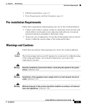
... for the switch installation: Caution The total maximum load on each AC-input power circuit must comply with sufficient overcurrent protection and direct grounding to the branch circuit. • To prevent a loss of input power, be sure the total maximum load on a dedicated circuit; Statement 1040 78-18039-02 Catalyst 4900 Series Switch Installation Guide...
... for the switch installation: Caution The total maximum load on each AC-input power circuit must comply with sufficient overcurrent protection and direct grounding to the branch circuit. • To prevent a loss of input power, be sure the total maximum load on a dedicated circuit; Statement 1040 78-18039-02 Catalyst 4900 Series Switch Installation Guide...
Installation Guide
Page 40
.... Heat dissipation is an important consideration for sizing the air-conditioning requirements for a switch. Refer to consult RFI experts. Site Power Requirements Chapter 2 Site Planning EMI Recommendations Follow these guidelines when setting up the site wiring. Catalyst 4900 Series Switch Installation Guide 2-4 78-18039-02 When planning the location of the new system, consider...
.... Heat dissipation is an important consideration for sizing the air-conditioning requirements for a switch. Refer to consult RFI experts. Site Power Requirements Chapter 2 Site Planning EMI Recommendations Follow these guidelines when setting up the site wiring. Catalyst 4900 Series Switch Installation Guide 2-4 78-18039-02 When planning the location of the new system, consider...
Installation Guide
Page 41
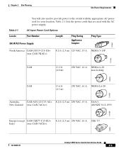
... Options Locale Part Number 300 W AC Power Supply Length Plug Rating Appliance Coupler Plug Type 120352 North America CAB-US515-C15-US= (was CAB-7KAC=) 8.2 ft (2.5 m) 125 VAC, 15 A NEMA 5-15P 120354 ... (except CAB-CEE77-C15-EU= 8.2 ft (2.5 m) 250 VAC, 16 A CEE 7/7 Italy) (was CAB-7ACE=) 120357 78-18039-02 Catalyst 4900 Series Switch Installation Guide 2-5 Chapter 2 Site Planning Site Power Requirements You will also need to provide power to the switch with the AC power supply. Table 2-1 lists the power cords that are used with the appropriate AC...
... Options Locale Part Number 300 W AC Power Supply Length Plug Rating Appliance Coupler Plug Type 120352 North America CAB-US515-C15-US= (was CAB-7KAC=) 8.2 ft (2.5 m) 125 VAC, 15 A NEMA 5-15P 120354 ... (except CAB-CEE77-C15-EU= 8.2 ft (2.5 m) 250 VAC, 16 A CEE 7/7 Italy) (was CAB-7ACE=) 120357 78-18039-02 Catalyst 4900 Series Switch Installation Guide 2-5 Chapter 2 Site Planning Site Power Requirements You will also need to provide power to the switch with the AC power supply. Table 2-1 lists the power cords that are used with the appropriate AC...
Installation Guide
Page 42
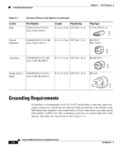
... then to the central office (CO) or other interior ground system with number 6 AWG wire. Grounding Requirements Chapter 2 Site Planning Table 2-1 Locale Italy AC-Input Power Cord Options (continued) Part Number CAB-C2316-C15-IT= (was CAB-7ACI=) Length Plug Rating Plug Type 8.2 ft (2.5 m) 250 VAC, 16 A 1/3/16 CEI 23-16... VAC, 10 A BS 546 203795 Grounding Requirements Grounding is recommended on the right side of the chassis, and either one may be used. (See Figure 2-1.) Catalyst 4900 Series Switch Installation Guide 2-6 78-18039-02
... then to the central office (CO) or other interior ground system with number 6 AWG wire. Grounding Requirements Chapter 2 Site Planning Table 2-1 Locale Italy AC-Input Power Cord Options (continued) Part Number CAB-C2316-C15-IT= (was CAB-7ACI=) Length Plug Rating Plug Type 8.2 ft (2.5 m) 250 VAC, 16 A 1/3/16 CEI 23-16... VAC, 10 A BS 546 203795 Grounding Requirements Grounding is recommended on the right side of the chassis, and either one may be used. (See Figure 2-1.) Catalyst 4900 Series Switch Installation Guide 2-6 78-18039-02
Installation Guide
Page 44
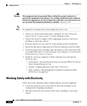
...rings and chains) or other items that suitable grounding is available. Avoid wearing any electrical equipment: • Locate the emergency power-off of a suitably installed ground conductor. United States-National Fire Protection Association (NFPA 70); United States National Electrical Code -... Commission (IEC) 60364, Part 1 through Part 7 Working Safely with the following local and national electrical codes: - Catalyst 4900 Series Switch Installation Guide 2-8 78-18039-02 Safety Overview Chapter 2 Site Planning Warning This equipment must be grounded. Never defeat the...
...rings and chains) or other items that suitable grounding is available. Avoid wearing any electrical equipment: • Locate the emergency power-off of a suitably installed ground conductor. United States-National Fire Protection Association (NFPA 70); United States National Electrical Code -... Commission (IEC) 60364, Part 1 through Part 7 Working Safely with the following local and national electrical codes: - Catalyst 4900 Series Switch Installation Guide 2-8 78-18039-02 Safety Overview Chapter 2 Site Planning Warning This equipment must be grounded. Never defeat the...
